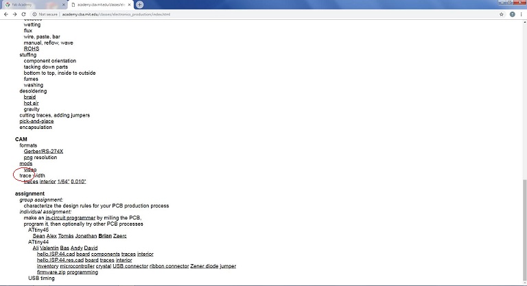
characterize the design rules for your PCB production process
characterize the design rules for your PCB production process
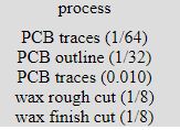
In this week, we have to characterize the specification of PCB production processes and learn how to work CNC milling machine. there are different types of PCB board and we use FR1. For cutting and traces we are using 1/32 and 1/64 drill bit respectively.
PCB Producton
For PCB must use PNGs file and and we download PNG file from Neil's lecture.
Downlaoding
After download png file we edit in paint for outline

Trace and outline
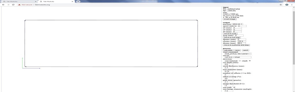
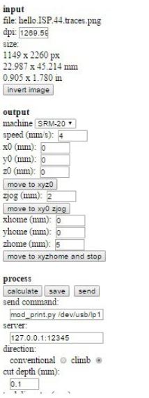
There are few steps for generating RML files
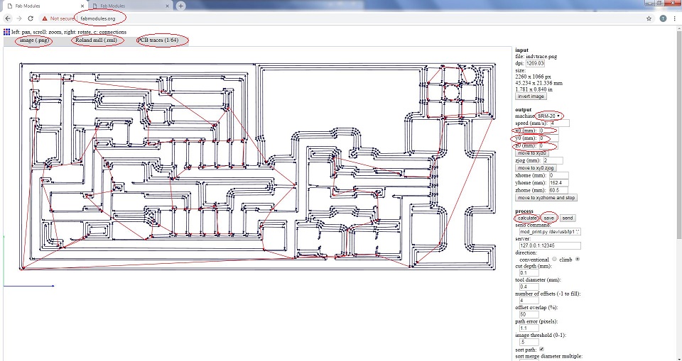
Calculation
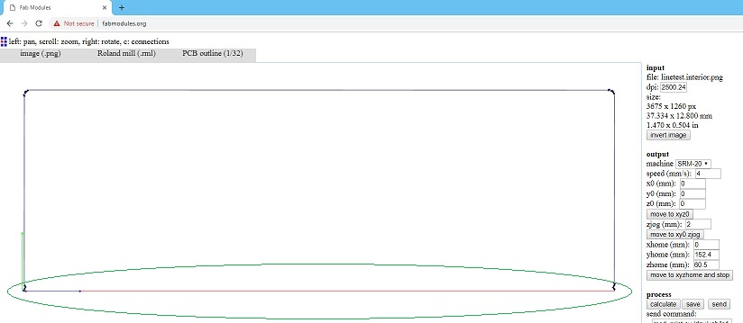
Same steps follows for outline,click on PCB outline 1/32 and click calculate to save the file.
Trace
while we generate rml file for outline it did not show the bottom line of outline and we told issue to instructor, he says that same problem they facec, and edited png file again in paint,then we generate outline .rml file.
Trace Calculation
After generating RML, sent both files to Rolan monoFAB SRM-20 machine and follow below steps.
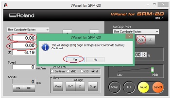
Setting of Vpanel
Click on "Cut" and delete all old files,then add new .rml file which you want to use.
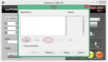
Deleting Old Files and Add new One
Click on "Output" to start the process
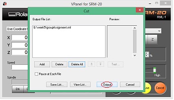
Click Output
We initially made a mistake with resolution while generating rml files.. Ignoring PCB image's default dimensions we changes its dpi/resolution from 5000 to 2000 that resuted increased size of the PCB
Output
After that we generate again .rml file using above method.
Final result
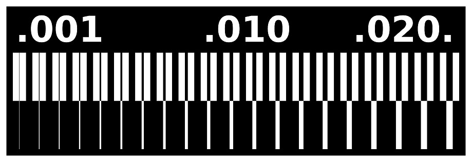
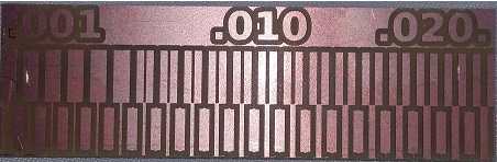
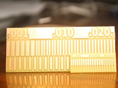
The group assignment shows that how much machine works precisely with 1/64 drill bit to show even 0.001 in.
Make an in-circuit programmer by milling the PCB,then optionally trying other processes.
During this week the goal was to learn how to fabricate a PCB from scratch using just FabLab devices.The target was to built a micro-controller programmer that will be useful for us in future weeks
.We did not have to worry about the design. It was already given to us.It is also very usefull thing too.
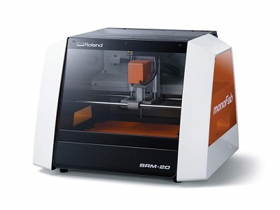
Our CNC milling machine. A Roland SRM-20
Here is our pcb layout of FabISP and its border for cutting
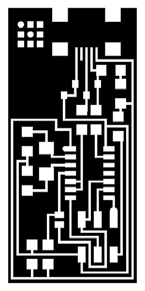

Trace and outline
Creating the .rml files
Before working with the CNC machine I had to create three different rml files: one to cut the traces, one to cut the board itself from the FR-4 and a third one to test that the size of the board and the milling bit
utilized is the appropriate one. rml format is a Roland's proprietary format for its CNC milling machines based on G-code. I utilized fabmodules to transform Brian's png files into rml files
There are few steps for generating RML files.
Trace and outline
Trace and outline
For Milling with Roland SRM-20 we are using VPanel software, it has a direct wired connection with the machine. Following image shows the GUI of this software and mine working with SRM20.
SRM-20
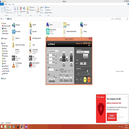
Vpanel
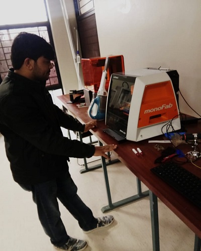
Interaction With SRM-20
There are few steps to work with this machine, are given below
Tools
now machine start milling my fabISP circuit. :)
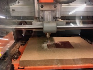
Machine While Milling
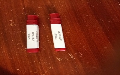
I used the BOM from the tutorial to find my components. Good practice is to ensure you have all components before milling.
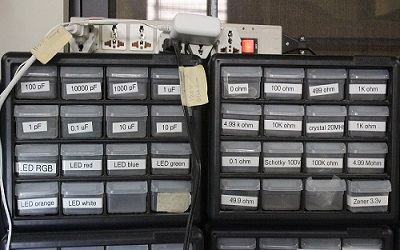
Choose Components
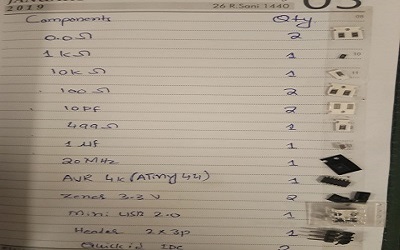
List Of Components
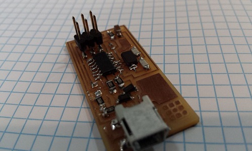
It took almost 3 hours to solder the ISP beacuse , i have not worked before with soldering and finally it is ready. :)
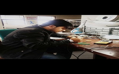
While Soldering
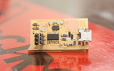
Ready
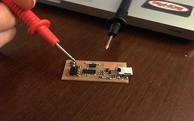
Testing
Following steps were required for the programming of ISP:
I used Ubuntu Operating System for the programming purpose.
Following steps were required for the programming of ISP :
=>Then type
=> - type "y" when asked to do so by your system
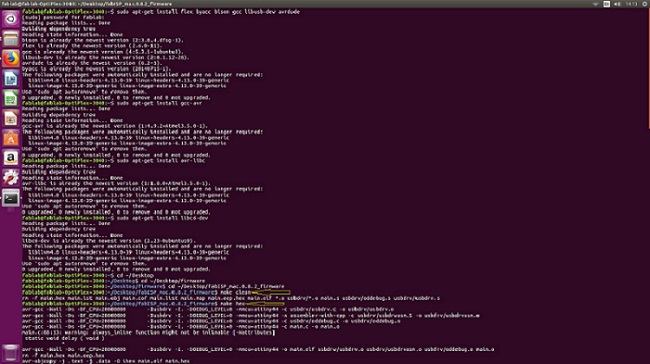
make clean" and "make hex commands
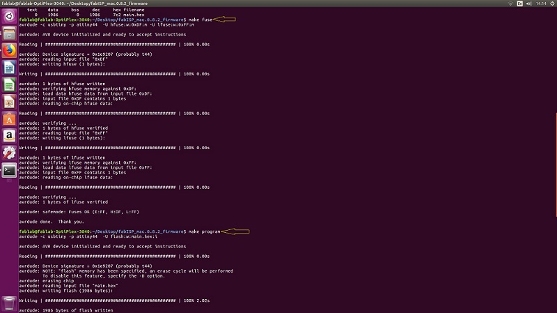
make clean" and "make hex commands
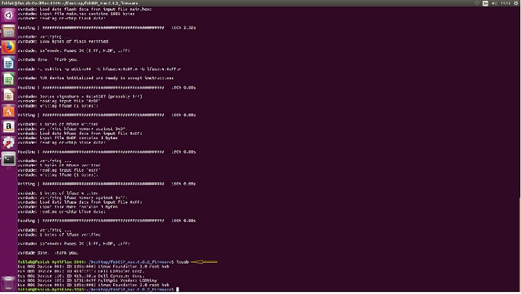
"lsusb command"
Once the programming was successful, I desoldered the 0 ohm resistors
"lsusb command"
and my fab isp was ready!
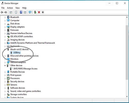
"lsusb command"
This is All about this week You may Download this week file from here
.png)