Week 17
Machine Design - Gillou Cocktail Part 2
MOOD OF THE WEEK

Gillou Cocktail here we come again ! Now that we've done the frame and the mecanism, let's automatize all this :)
I had a small part, but still tricky to do since we have to think each board in a way they can communicate with the master one.
We're in the last changes, last adjustments. Hope it will work ! :)
Machine Design - Gillou Cocktail part 2
This week's assignments :
- Group assignment
- actuate and automate your machine
- Han Solo assignment :
- document the group project and your individual contribution
Group Assignment
Here is the link to our documentation for the group assignment : http://fabacademy.org/2019/labs/sorbonne/group_work/gillou/
There you can find how the machine works all together :) As a summary, here is how it works :
Basically, the idea with this machine is to have one mother board that will talk with all of the other board in the machine.
The mother board will be based on a esp8266. This will allow us to have the possibility to create an web interface or an app to control the machine.
Then the job of the mother board is to send an action to one of the other part, wait for a receipt and pass to the next action to do. Here this is the algorythmic diagram of the process :
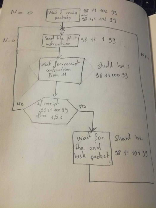
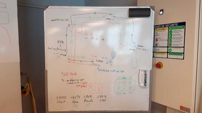
As you can see he idea is that every board of the machine have an adress and we communicate through 2 serial communication bus (TX and RX) Then we created a starndart message composed by [start_byte, adress, parametre, end_byte].
Then we created a 2 x 3 pins connector that include 2 pins for the 12V 2 pins for the GND, 1 pin for TX and 1 pin for RX. The mother board get the 12V and then distribute it to the other boards.
For exemple this is the packet to start the decoration I made : 98 31 1 99
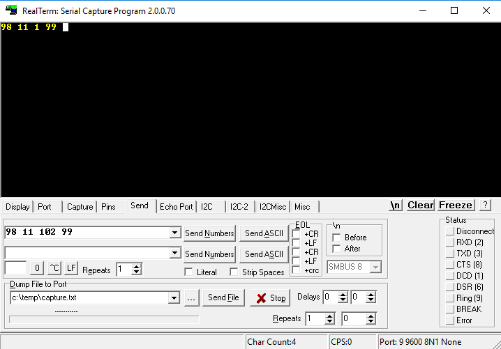
And finally, in order to test if the message are well sended we used realterm. This little soft allow us to check serial communications by selecting th type of data, baudrate and lot of other settings. In our case it is setup to 9600 baud and uint8.
If you want to know in more detail what has been done, do not hesitate to check out the group documentation !
Han Solo Assignment
Step 0 : choosing a motor, adding a gear to it and checking the other gears work with it
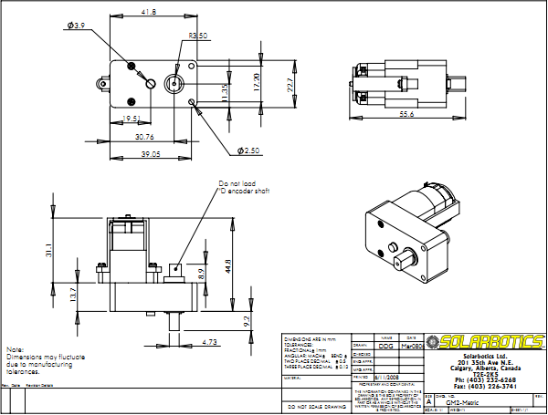
I need a simple DC motor to make my gears work. In the numerous motors I found in the lab, I need one with a good engine couple. I chose the offset shaftGM2 Gear Motor. They are very comparable to a hobby servo for power, at a fraction of the cost!
- Mechanical Features :
- 7mm output shaft with double-flat outputs
- Secondary output shaft (D) for encoders (not meant for rotational loads)
- Built-in safety ratchet clutch set for 60 in*oz torque (easily modified for full "locked-up" operation)
- Built-in mounting holes
- 55x48x22.7mm (2.17x1.89x0.894")
- 31.4 grams (1.11oz)
- 3-6VDC nominal operation
I designed a small piece in 3D so I can clip a gear to the motor. In order to do it quick, I used Tinkercad instead of Openscad. It's pretty useful to draw small simple geometrical pieces quickly.
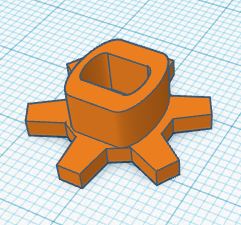
Here are the pictures of everything together :)
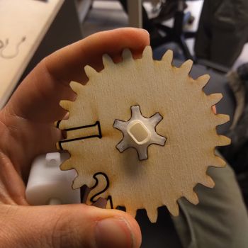
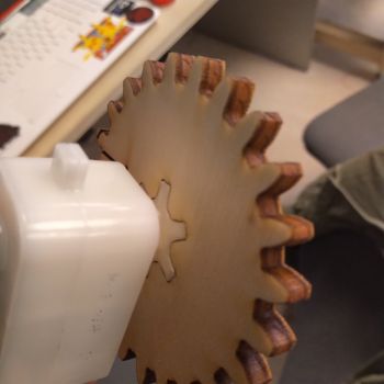
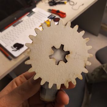
I plugged it to an power supply just to see if the engine couple was strong enough to make all the gears go round... and it works !
Step 1 : designing and milling the board
My gears are working fine, I just have to make them work with the board I'll design. Well, "just" is not the right word ^^'
I designed a first board, but I made the mistake of not checking how to use a motor with a board. I thought I only had to connect it with a VCC and a GND, but it's a bit more complex than that. Here are the first design and schematic :

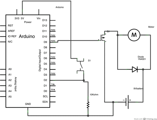
This time I checked on the internet, and I found this tutorial and schematic that helped me understand how to control a DC motor with my board. I also added a button and a led to be able to test how to start and stop my motor before trying to connect it to the other boards.
-
Tutorials :
- https://cdn.sparkfun.com/assets/resources/4/4/DC_motor_circuits_slides.pdf
- https://www.arduino.cc/en/Tutorial/TransistorMotorControl
- https://www.tutorialspoint.com/arduino/arduino_dc_motor.htm
- https://www.allaboutcircuits.com/projects/control-a-motor-with-an-arduino/
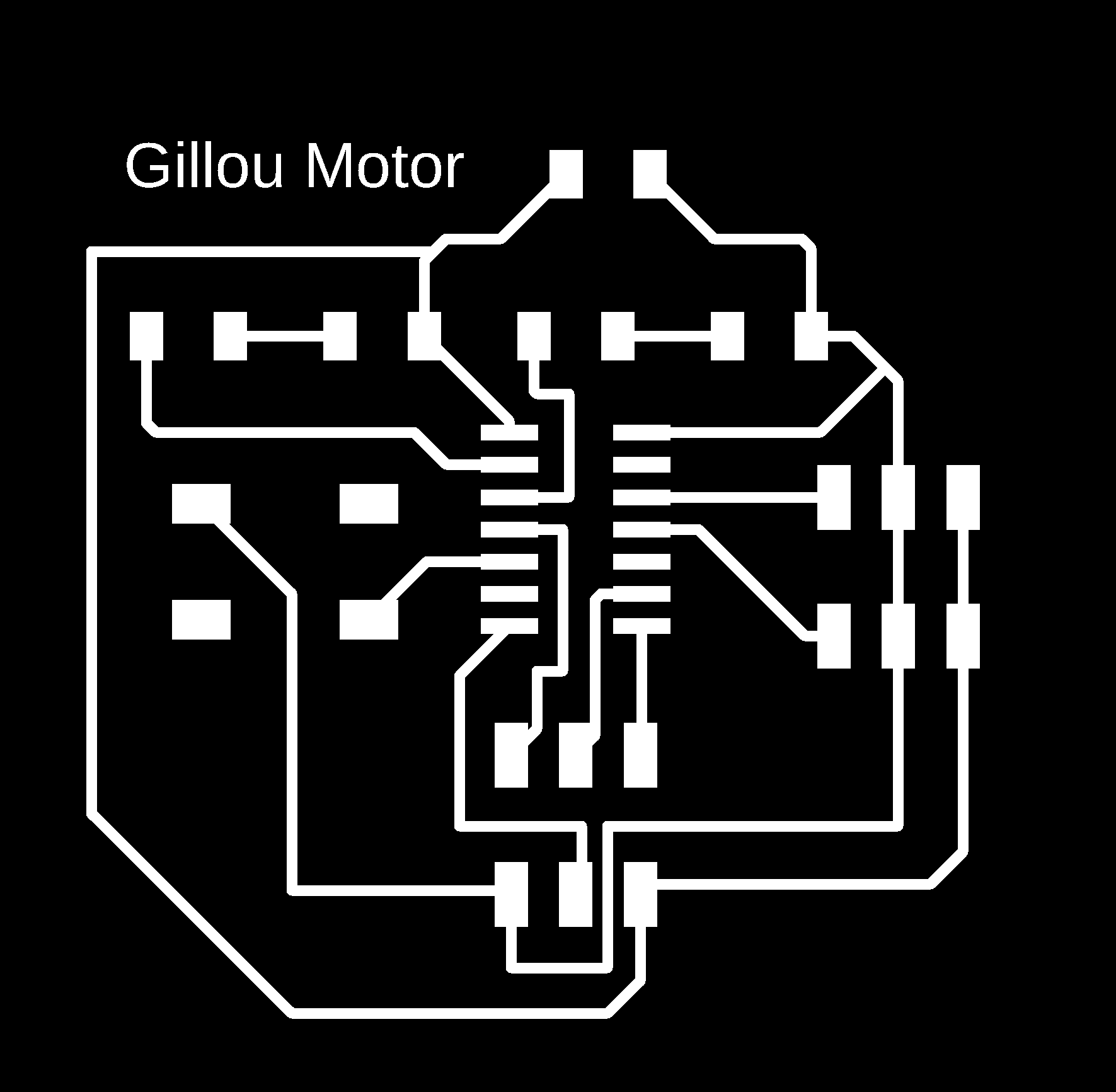
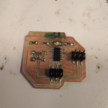
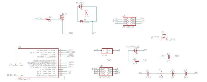
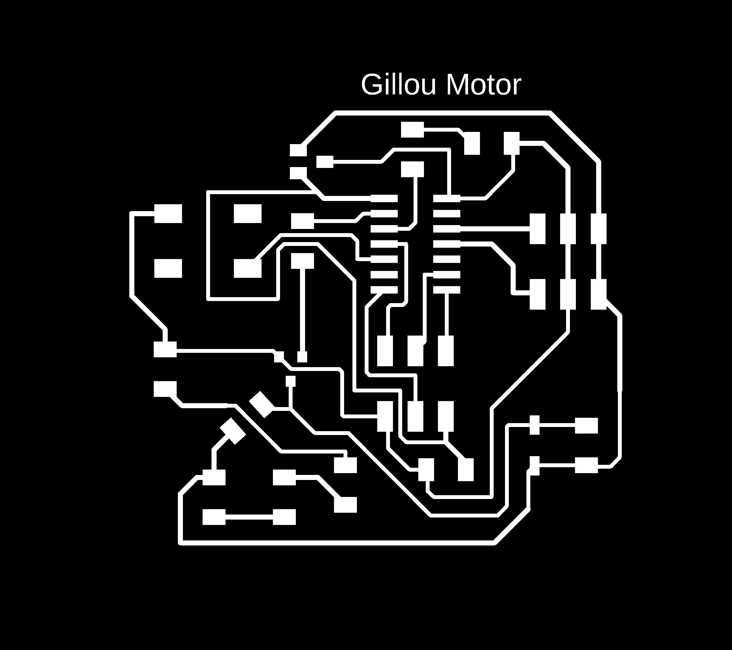
Here are my schematic, design and photo for my second design :

Still, I made some mistakes while designing and soldering my board : I put the regulator upside down. What did it do ? it just burnt and made smoke when I tried to supply it with 12V ^^'
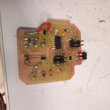
Guess who had to redo here board all over again ? ME ! ^^ And since I'm pretty smart, I made a mistake while milling it again, and I had to patch my regulator upside down so it won't burn again. I also took away the diode, that was actually useless here.
Here is the new result !
This time it works just fine !! :D Now I have to upload my code to test it and make sure I can control it properly.
Step 2 : programming my board and motor alone
Actually the code to control the board is pretty simple. Like for the LEDs, you can put them as an OUTPUT and control to turn it on and off with a simple digitalWrite(); function.
Here is my test code :
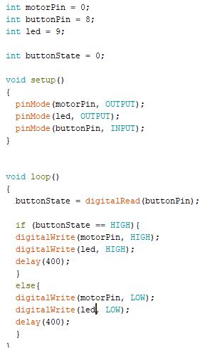
It's not spinning fast, but it works ! I can stop the gear from turning by pushing my button. It also turns off the LED.
Now comes the tricky part... changing the code to make it understandable by the master board and work at the right time !
Step 3 : programming my board and motor with the other parts
First, I had to change the code. Since Leo is the master board, he helped me understanding how my board shoudl communicate with his. Here is the code explained step by step :
-
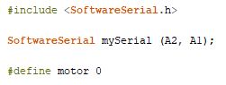
Since we're gonna communicate with TX and RX, I need to upload the SerialSoftware library. And then just define which pin my motor is using. Here it is the
0. -
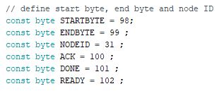
In order to communicate with one another, and to know when each slaves' task is done, we send messages to the master board. in this block, we define each message's name and a specific number indicating what's happening :
- when it starts
- when it ends
- my node ID
- the acknowledgment of receipt (sent to the master board whenever he sends me a message, to tell him I received it well)
- when my task is done
- when I'm ready to receive an order
-
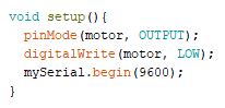
Now we have to
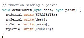
setup, to initiate my board. In the setup I put my motor toLOWso it won't start turning immediatly when the power supply is on. - In this function, we declare a function that sends a packet, with in its parameters a destination byte and a parameter byte. With this function, we can now send packets.
-
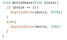
This is the function controlling my motor. It says :
- in the function called
motorGearthat takes a parameter calledboule(I changed the spelling since I can't useboolas a variable name) - if the variable
boulereceives1as a message (meaning the whole process of making a cocktail started), turn the motor on. - Otherwise, turn it off.
- in the function called
-
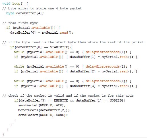
Here is the most tricky part of the code, the
void loop.- We declare an array, where we'll store four bytes.
-
There is one big
ifthat stores all the rest of the code. It gets activated if it received data from the serial, so if there is a trigger message from the master board. - Here, we read the first byte that comes from the serial.
-
If the byte that is read is the
start byte, then we store the rest of the packet. -
We check if the packet is valid and if the packet is for this node or not. If so, it will send an acknowledgment of receipt, execute the function
motorGear();and send a message to tell the master board its job is done.
And here is a video of the packages being sent like explained earlier in my documentation. I fixed my motor by using a hot glue pistol, so I'm sure it won't move. And it works really well ! If I had more time I would build a support, but it's gonna be for a Gillou 2.0 version :)
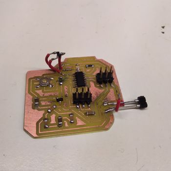
Here is the inside of the machine, with my board and Madjid's one.
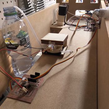
Here is a video of the machine with each parts. Do not hesitate to consult the group documentation to find out more about how everything works together if it's not clear yet ! :)
Wanna try by yourself ?
Here are all the links to my files, feel free to download them :
| Name of the documents | Link to download |
|---|---|
| Arduino files | Motor test |
| Arduino files | Slave code |
| 3D STL File | Piece to add the gear to the motor |
| Eagle files | Schematic |
| Eagle files | Board |