18. Wildcard week
Assignment
- Design and produce something
- Document the requirements that your assignment meets
- Include everything necessary to reproduce it
Group project
Our project is focused on textiles, it consist of two steps :
- Test and automatize the production of nylon thread artificial muscles
- Integrate the artificial muscle in fabric
As the automation could not be achieved by a single person in one week, we decided to work on separated parts of it’s design.
Group project is documented on it’s dedicated page.
Revolution counter
My part of the design was to make an electronic circuit that would control the motor and count the number of turns that are completed, in order to stop the motor when it reaches the number of turns that is preset.
It uses a photo-switch mounted on 3D printed parts :
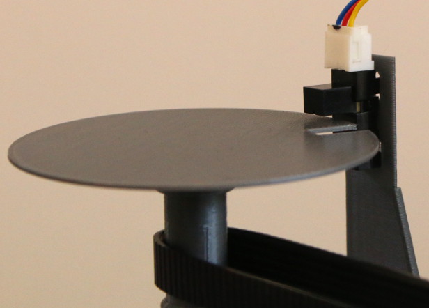
The photo-switch is scavenged from a printer (the same one that provided the DC motor) and I had no datasheet to help with the wiring. So I opened the case to find how it is wired. Here you can see the LED (transparent) and the photo-transistor (black) :

I used a multi-meter to find the polarization of the LED. As the anode was common to both devices, I knew this also was the photo-transistor’s emitter (assuming it’s a NPN transistor).
The LED needs a protection resistor so I used a potentiometer to find a resistance value that would switch the photo-transistor without burning the LED. A 3k3 resistor could have done the job, but here I used a 4k7 resistor and it works fine.
PCB
The circuit is just meant to connect an Arduino Nano to these devices :
- An optical switch (for counting turns)
- A MOSFET module (to control the motor)
- A rotary encoder
- An OLED display
Here is a picture of the board, when counting :

Arduino code
#include <Wire.h>
#include <Adafruit_GFX.h>
#include <Adafruit_SSD1306.h>

#include <ClickEncoder.h>
#include <TimerOne.h>

#define sensor 2
#define PWM 6

Adafruit_SSD1306 display(13);

ClickEncoder *encoder;
void timerIsr() {
  encoder->service();
}

volatile unsigned int count = 0;
unsigned int previous = 0;
unsigned int turns = 100, setpoint = 0, last = 0;
boolean turning = false;

void setup() {
  display.begin(SSD1306_SWITCHCAPVCC, 0x3C);
  display.clearDisplay();
  display.display();

  encoder = new ClickEncoder(4, 3, 5, 4);
  encoder->setAccelerationEnabled(true);
  Timer1.initialize(1000);
  Timer1.attachInterrupt(timerIsr);

  pinMode(sensor, INPUT_PULLUP);
  pinMode(PWM, OUTPUT);
  digitalWrite(PWM, LOW);

  attachInterrupt(digitalPinToInterrupt(sensor), counter, FALLING);
}

void loop() {
  ClickEncoder::Button b = encoder->getButton();
  if (b == ClickEncoder::Clicked) {
    if (turning) {  // go back to setting
      digitalWrite(PWM, LOW);

      turning = false;
      last = 0;
    }
    else {  // start turning
      setpoint += turns;

      digitalWrite(PWM, HIGH);

      turning = true;
      previous = 0;
    }
  }

  if (not turning) {
    turns += (encoder->getValue())*10;
    if (turns != last) {
      if (turns < 1)
      {
        turns = 1;
      }
      display.clearDisplay();
      display.setTextColor(WHITE);
      display.setTextSize(2);
      display.setCursor(0, 0);
      display.print("Setpoint");
      display.setTextSize(3);
      display.setCursor(0, 30);
      display.print(setpoint);
      display.display();

      last = turns;
    }
  }
  else {  // if turning
    if (count == setpoint) {
      digitalWrite(PWM, LOW);
    }
    if (count != previous) {
      display.clearDisplay();
      display.setTextColor(WHITE);
      display.setTextSize(2);
      display.setCursor(0, 0);
      display.print("Turn count");
      display.setTextSize(3);
      display.setCursor(0, 30);
      display.print(count);
      display.display();

      previous == count;
    }
  }
//  delay(1);
}

void counter() {
  count ++;
}
Individual project
In order to complete the assignment, I attempted to make a composite replica of my 3D printed planter.
Openscad model and STLs are available here.
For this assignment, I used a 3D print of the 120mm version in PETG-G with 0.2mm layer height on a Prusa i3 MK3.
My plan is to use thermoforming to replicate the outside surface of the 3D print. Then replicate the inside surface. Finally, I will assemble both surfaces and fill the inside with a polymer.
Thermoforming
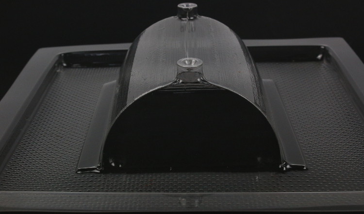
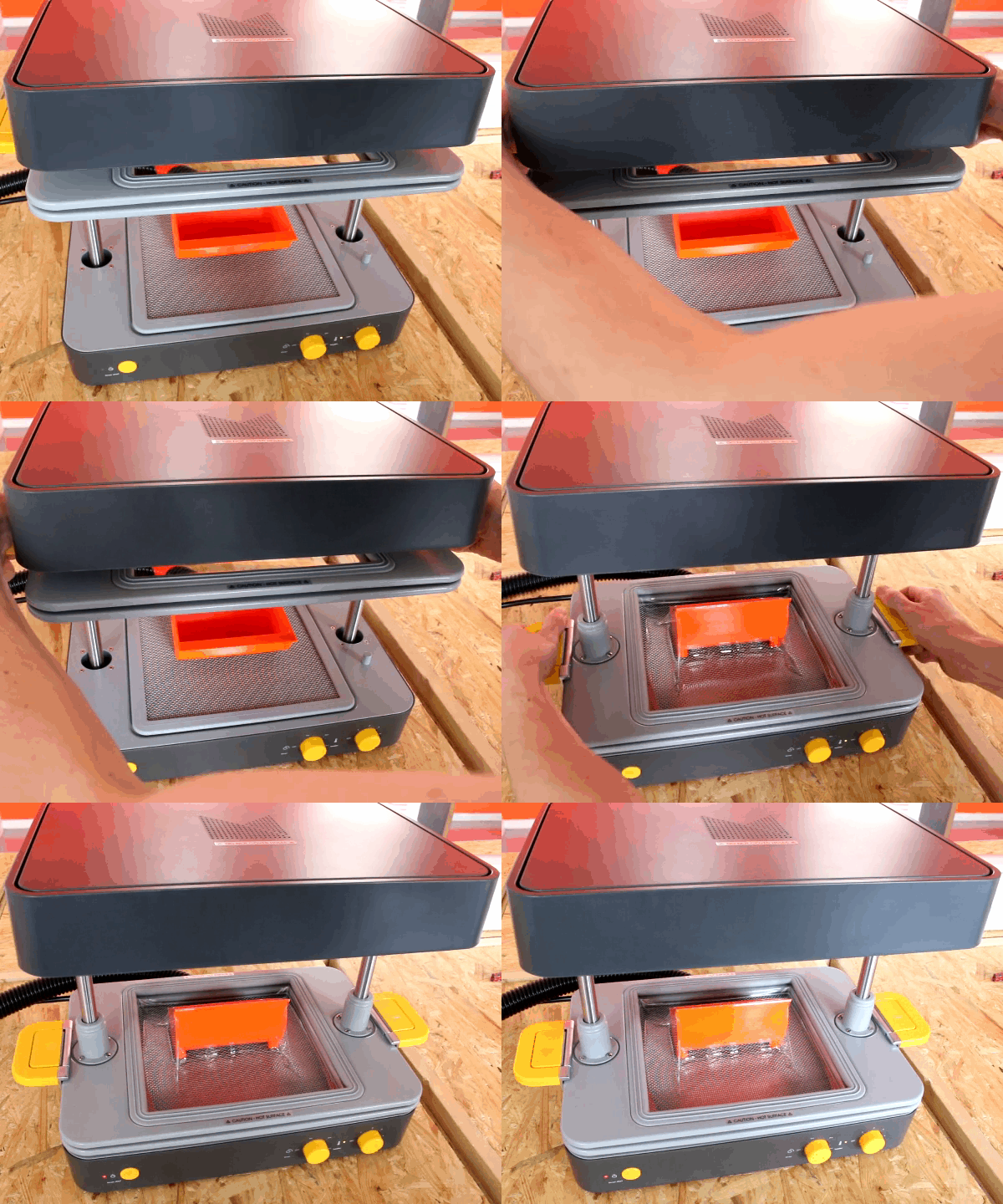
I will use our Mayku Formbox Vacuum Former with 0.5mm PET-E sheets (Mayku Cast Sheets).
Thermoforming the outside was easy. As the 3D print was sitting in stable position, I could get an accurate form at the first attempt :
Inside surface was tricky because the 3D print was not stable in this position :
So here is the result :

I want the inside surface to fit into the outside surface, so I need to remove it’s contour.
I opened it with a scalpel :

Then I cut around with scissors :

And this is what I got :

It does fit in the outside surface.
Filling with polymer
As I want to make a lightweight composite, I attempted to fill the mold with polyurethane foam. I used Xencast PX30 Soft Flexible Polyurethane Rubber, expecting it would turn into foam when placed under vacuum.
So I placed the outside surface in the vacuum chamber and poured polyurethane into it :
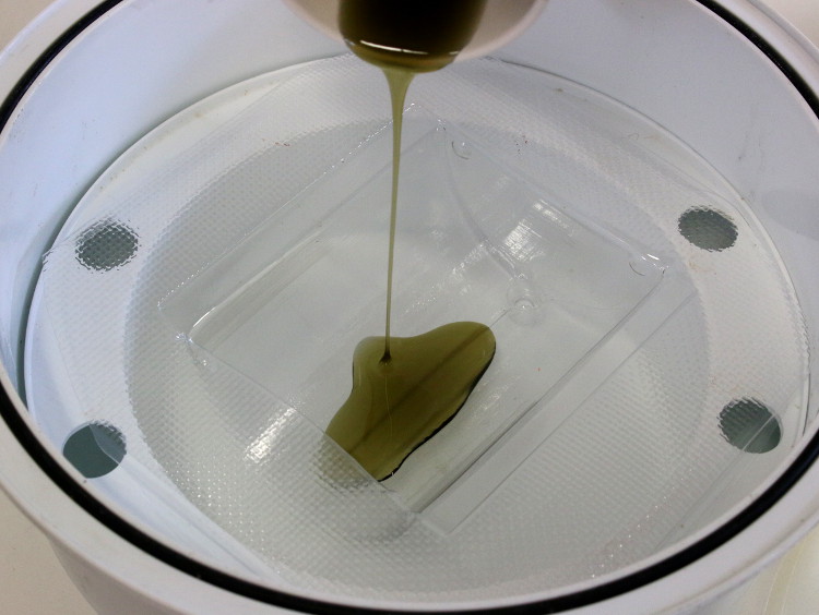
I tried to cover all the surface :
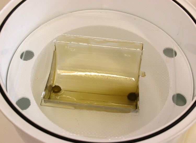
Then I placed the inside surface into it :
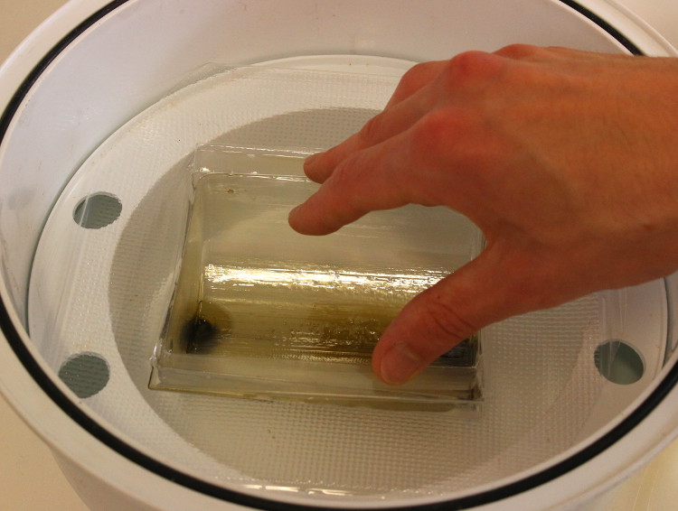
And I degassed it :
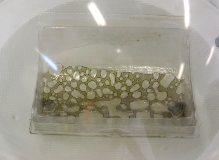
At first, air bubbles appeared as expected. But soon, air separated from polyurethane and I got no foam at all.
And here is the result, after curing :

Definitely not what I expected, but the structure is now solid and I believe that I’m not far from a good process for making composites.
CAD files
- EAGLE files for the user interface are archived in Nano_board.zip
- Openscad model and STLs for 3D printed planters are archived in Planter.zip