15. Networking and communications
This week I worked on defining my final project idea and started to getting used to the documentation process.
This weeks Assignment: 
-
Individual assignment:
- Design, build, and connect wired or wireless node(s) with network or bus addresses.
-
Group assignment:
- Send a message between two projects.
For this weeks group assignment you can check our page by clicking here
First part:(individual assignment): 
- For this weeks assignment I start to define the different types of communications :
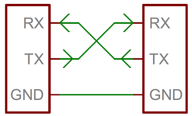
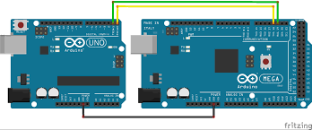
1- Networking - Serial:
* In telecommunication and data transmission, serial communication is the process of sending data one bit at a time, sequentially, over a communication channel or computer bus. This is in contrast to parallel communication, where several bits are sent as a whole, on a link with several parallel channels.
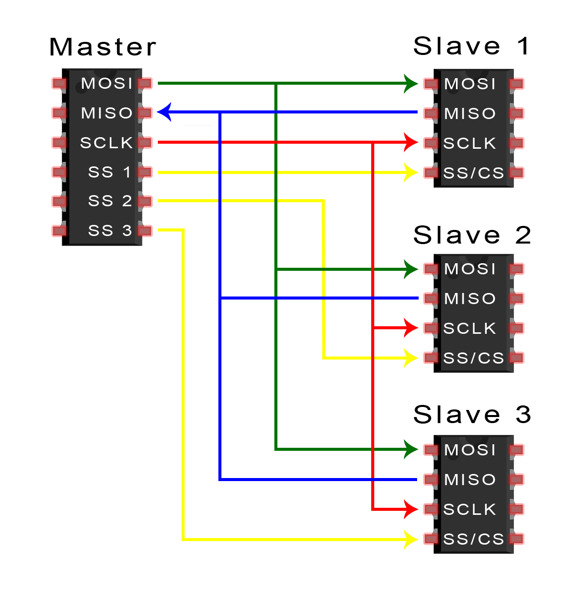
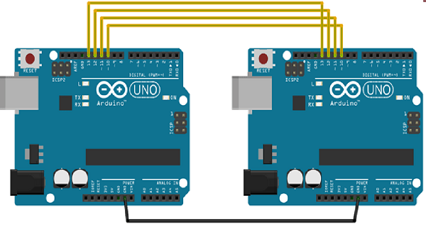
2- Networking - SPI:
* The Serial Peripheral Interface (SPI) is a synchronous serial communication interface specification used for short-distance communication, primarily in embedded systems. ... SPI devices communicate in full duplex mode using a master-slave architecture with a single master.
3- Networking - I2C:
* I²C, pronounced I-squared-C, is a multi-master, multi-slave, serial computer bus invented by Philips Semiconductor. It supports several slaves (eg 100+) allowing one transmission per time between the master and one slave. The transmission is not full duplex.

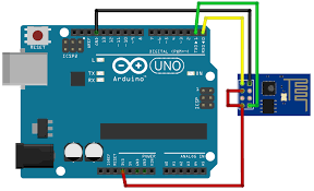
4- Networking - WiFi:
     * Wireless communication or wifi involves the transmission of information over a distance without the help of wires, cables or any other forms of electrical conductors.

     * Wireless communication is a broad term that incorporates all procedures and forms of connecting and communicating between two or more devices using a wireless signal through wireless communication technologies and devices.

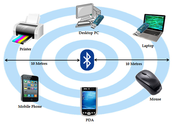
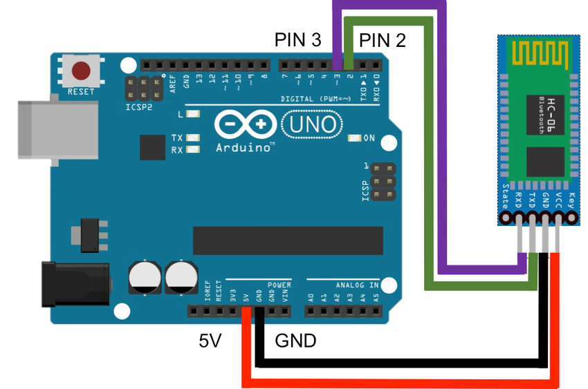
5- Networking - Bluetooth:
* Bluetooth technology is a short-range wireless communications technology to replace the cables connecting electronic devices, allowing a person to have a phone conversation via a headset, use a wireless mouse and synchronize information from a mobile phone to a PC, all using the same core system.
6- Networking - Radio:
* Radio Communication. telecommunication by means of radio waves. Radio communication requires the use of both transmitting and receiving equipment. The transmitting equipment, which includes a radio transmitter and a transmitting antenna, is installed at the point from which messages are transmitted.
-
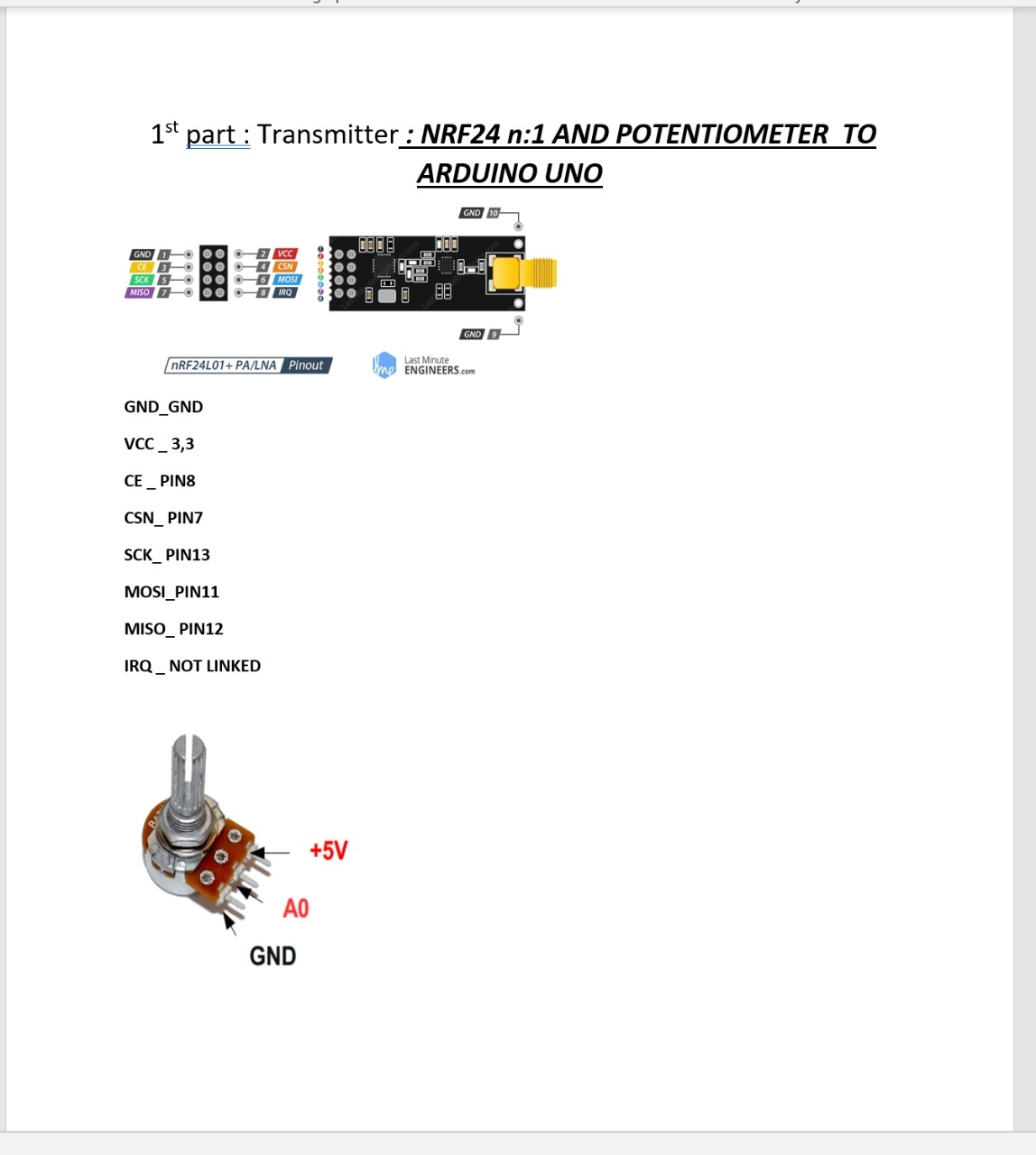
For this weeks assignment and for my final project the emergency robot, I choose to work with the radio communication (nrf24 as a device )
-
Let’s start :
-
first of all i designed a board in which I can link the nrf 24 .
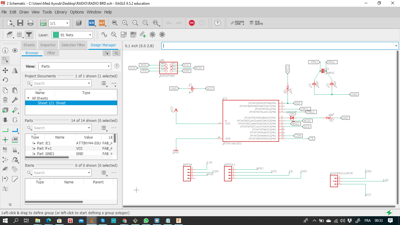
Nrf24 Schematic, Board and components:
COMPONENTS:
- Attiny44
- cristal 16 mhz
- x2 M04 FOR THE NRF24 PINS
- Red LED
- M3 for the voltage regulator pins
- 1X AVRISPSMD
Schematic:
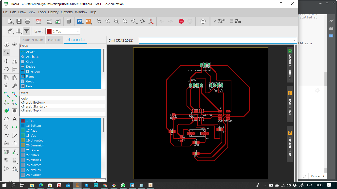
Board:
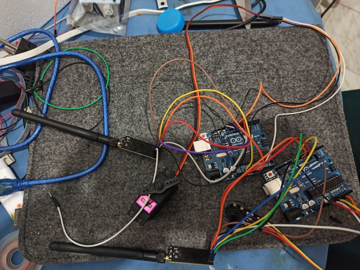
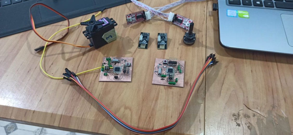
Using two nrf24 with two arduino:
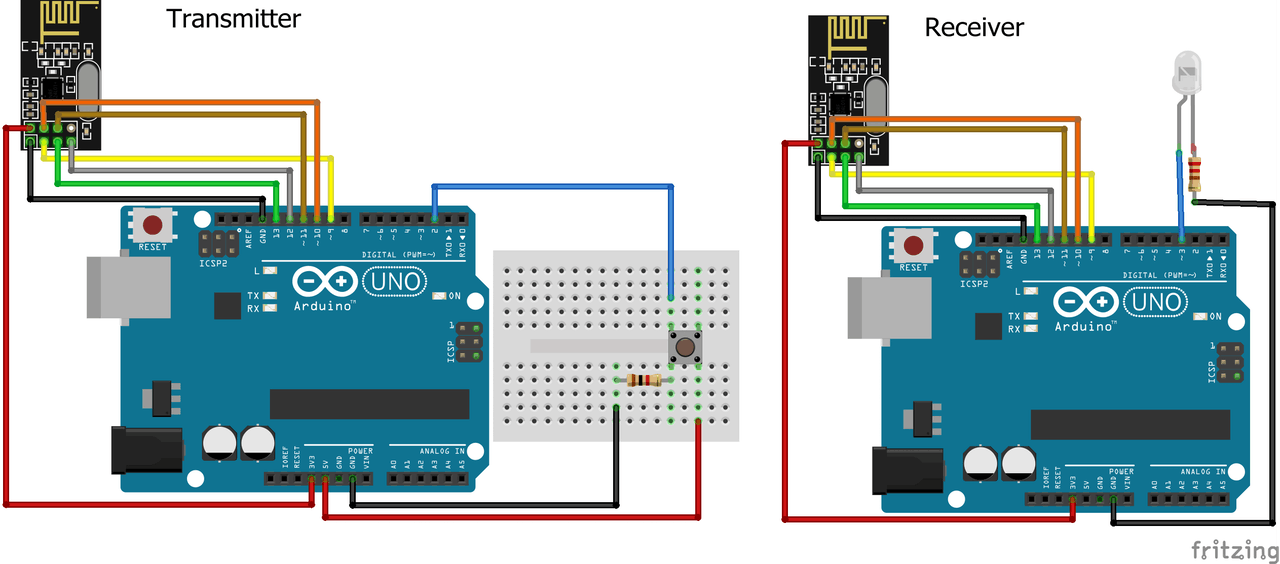
A- You need 2 nrf24, 2 arduinos, servo motor and a potentiometer after that you link them as it shows below:
1st Arduino (Transmitter)
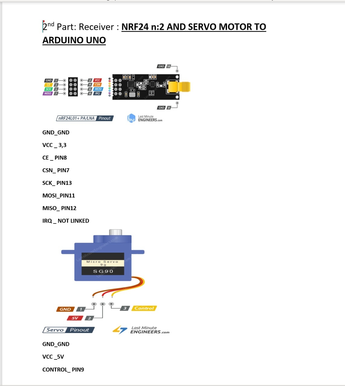
2nd Arduino (Receiver):
After doing the right connection you need to upload the code for the transmitter and the reciever
The codes!
1-Transmitter;
#include <RF24.h>
#include <RF24Network.h>
#include <SPI.h>

RF24 radio(8, 7); // nRF24L01 (CE,CSN)
RF24Network network(radio); // Include the radio in the network
const uint16_t this_node = 00; // Address of this node in Octal format ( 04,031, etc)
const uint16_t node01 = 01;

void setup() {
SPI.begin();
radio.begin();
network.begin(90, this_node); //(channel, node address)
}

void loop() {
network.update();
unsigned long potValue = analogRead(A0); // Read the potentiometer value
unsigned long angleValue = map(potValue, 0, 1023, 0, 180); // Convert the value to 0-180
RF24NetworkHeader header(node01); // (Address where the data is going)
bool ok = network.write(header, &angleValue, sizeof(angleValue)); // Send the data
}
2-Reciever:
#include <RF24.h>
#include <RF24Network.h>
#include <SPI.h>
#include <Servo.h>

RF24 radio(8, 7); // nRF24L01 (CE,CSN)
RF24Network network(radio); // Include the radio in the network
const uint16_t this_node = 01; // Address of our node in Octal format ( 04,031, etc)

Servo myservo; // create servo object to control a servo

void setup() {
SPI.begin();
radio.begin();
network.begin(90, this_node); //(channel, node address)
myservo.attach(9); // (servo pin)
}

void loop() {
network.update();
while ( network.available() ) { // Is there any incoming data?
RF24NetworkHeader header;
unsigned long incomingData;
network.read(header, &incomingData, sizeof(incomingData)); // Read the incoming data
myservo.write(incomingData); // tell servo to go to a particular angle
}
}
Important point
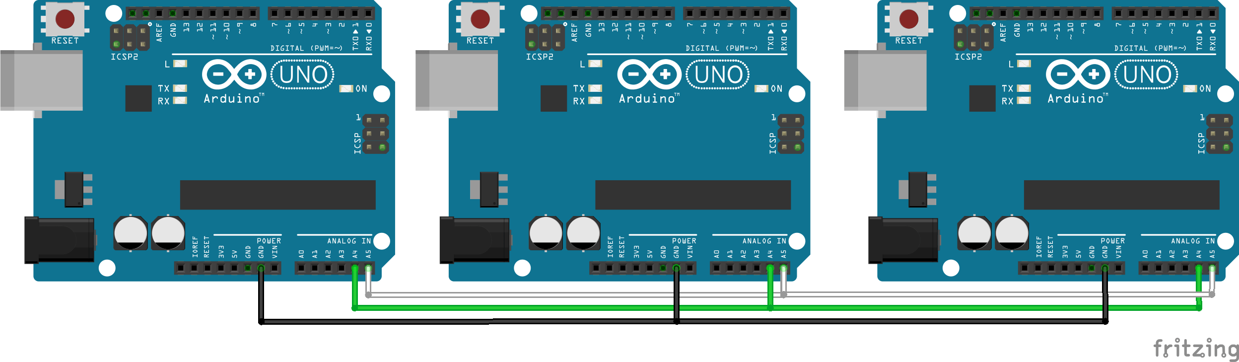
After uploading the codes for the transmitter and the receiver you need to use HUB wityh meany USB ports to link the two arduino and keep them both linked each in a different port and for each arduuino software in which the codes are written you open the serial ports as it is shown below in the image for example: the 1st arduino is attached to port A and the 2nd arduino is arrached to port B , you need to upload the suitable code for each through the right COM then open for both the serial window to see the information exchange .
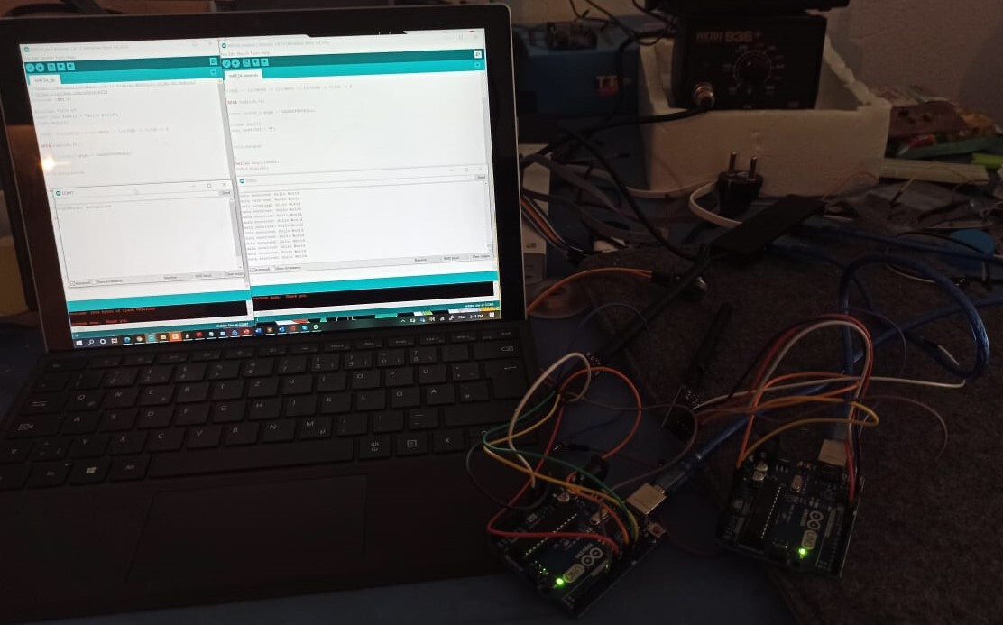
And voila , the work is perfectly done ^^
For this week I tried to design two different boards, one is working as a receiver with a servo motor and NRF24 and the other as a transmitter with a potentiometer and of course an NRF24
I wanted at 1st to highlight some information about the microchip I used in this week , which was the Atmega328p the same as in the arduino uno :
Here are the pinsout of the chip :
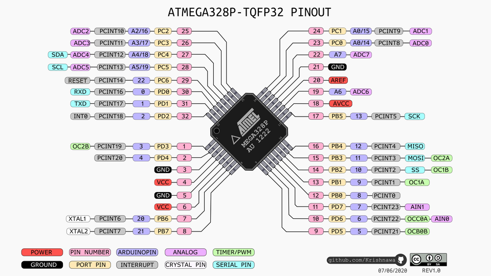
And here is the datasheet of the chip it was too useful to succeed in this week
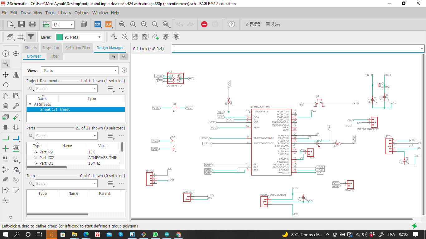
-1st Board (Transmitter):
1- Atmega328p
2- 7 pins headers for the NRF24
3- 3 pins headers for the potentiometer
4- 3 pins headers for the voltage regulator 3.3v
These was the important parts of my 1st board
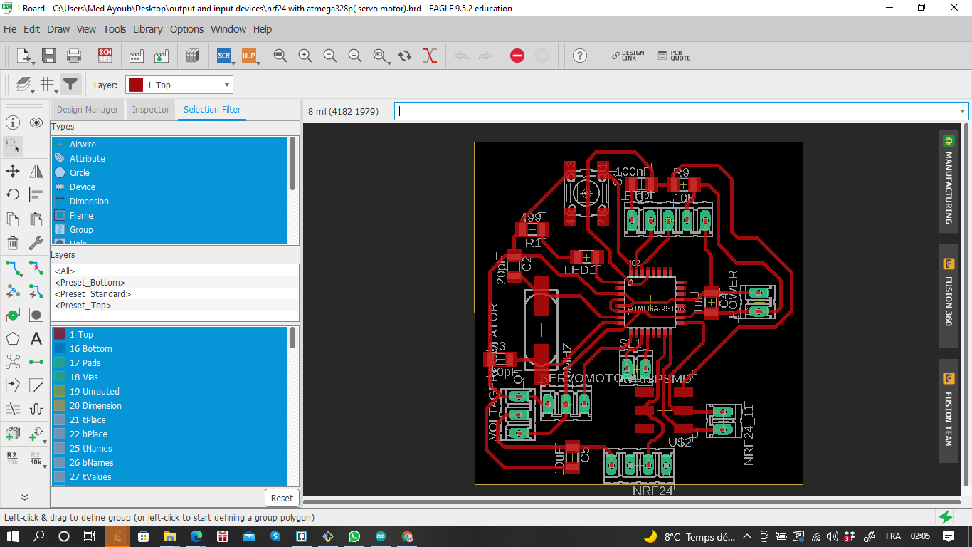
Here is the schematic:
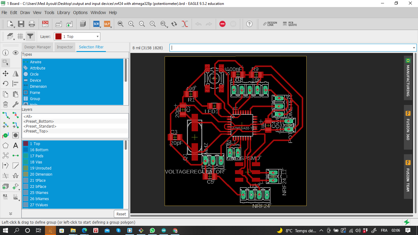
The board:
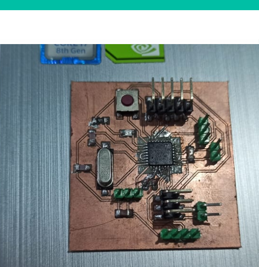
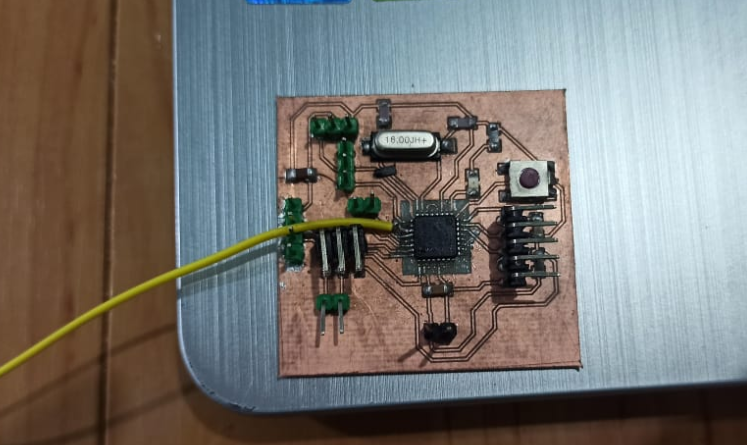
The final result after soldring process:
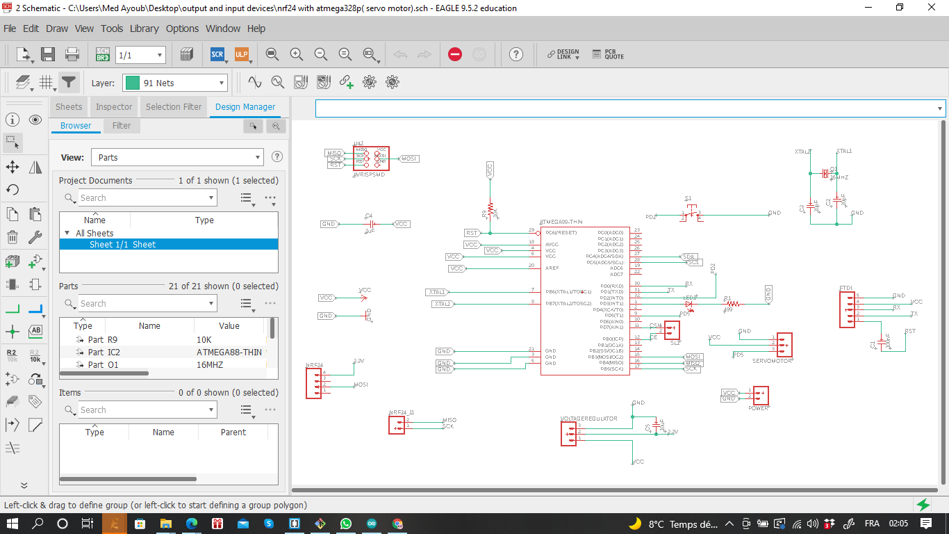
-2nd board (reciever)
1- Atmega328p
2- 7 pins headers for the NRF24
3- 3 pins headers for the servo motor
4- 3 pins headers for the voltage regulator 3.3v
The board schematic:
The board:
While soldring my board, I made a mistake when I was trying to fixe the CSN pin of the Nrf24 headers, the solder gun was too hot so, the trace was cutted , for that I tried to solder a jumper to fixe that issue and it worked perfectly as it is shown below :
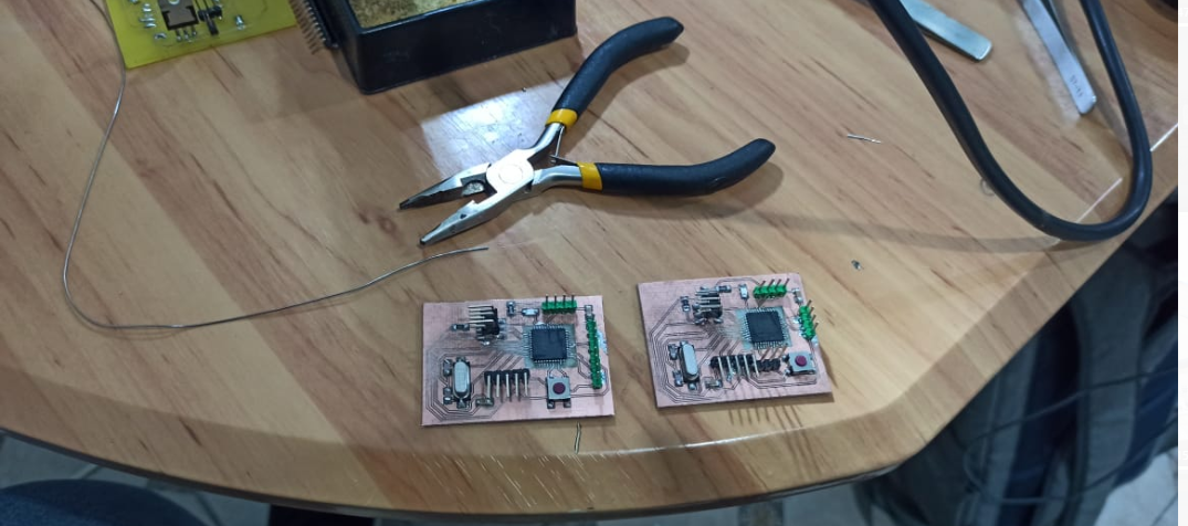
Here are the Two boards :
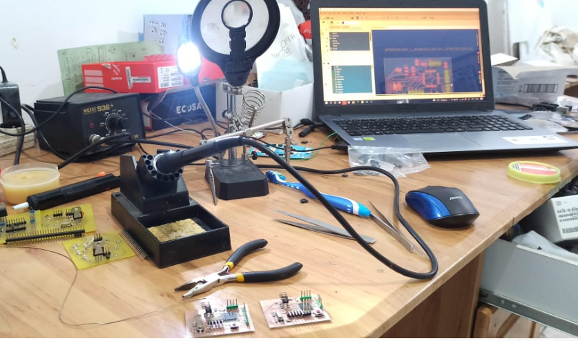
The needed tools
Wires connections and programming
For the both boards I needed to link the nrfs24 correctly as the photo up in the begininng of the week , then the potentiometer and the servo motor for their pins , after checking the connection were fine I linked the 1st board to the ftdi and I uploaded the 1st code of the transmitter then I disconnected the board then do the same for the 2nd but , an important point to be considered was that I reopened the IDE one more and paste the 2nd code there and without closing the 1st sketch of the trasmitter.This process in the reason to have two COMs at the same time to use it in serial communication after and that all was after burning the boatloader for both boards.
Connections
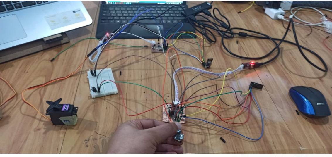
After uploading the codes for both Transmitter and reciever boards and checking all of the connections , It’s time to test the work and below are the steps I used to do that:
1- Connect both ftdi to the two boards
2- Checking the suitable COMs for each board
3- Open the serial port for both COMs
4- Turning the potentiometer
After Turning the potentiometer I discovered that the servo motor was turning simultaneously with my hand action and there was a transmittions between both serial ports , for that the work was perfectly done by me^^