Week8 – 2020.3.25
9.Embedded Programming
Objective:
Read a microcontroller data sheet;
Program my board to do something, with as many different programming languages and programming environments as possible;
Program my board
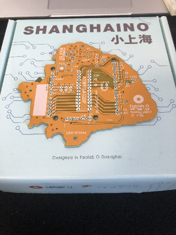
For the board we are going to program, we decide to use a breadboard. But it’s said that the breadboard has connectivity problems. So we are using it only for convenience purposes. We take all our components from Shanghaino, an Arduino board designed in the shape of Shanghai, where the lab is located.
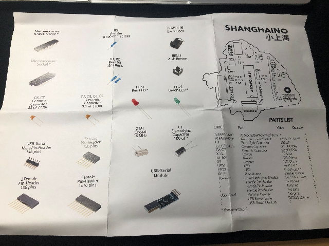
Here are the components we use:
1x ATMEGA328P
1x 100uF Capacitor
4x 0,1 uF(104) Capacitor
2x 22 pF(220) Capacitor
1x 10K Ohms Resistor
2x 220 Ohms Resistor
1x Blue LED
1x Green LED
1x 16 MHz Crystal
1x USB-Serial Module
12x wires
A picture describes all the components.
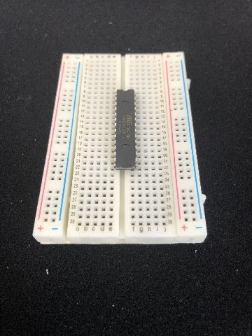
So this is how a breadboard works, each pin is connected horizontally. But for the columns on the two sides, they are not only connected horizontally, but also vertically. When setting up the breadboard, we get a lot of helps from this tutorial.
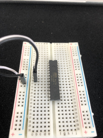
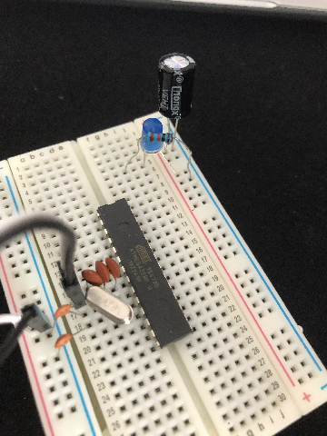
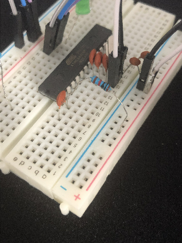
Now first, add the microcontroller to the board.
Here is a ATMEGA 328P pin map. And because the pin numbers of the ATMEGA and the pin numbers in Arduino are different, so it will also be helpful later during programming.
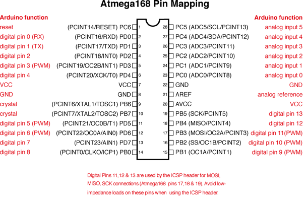
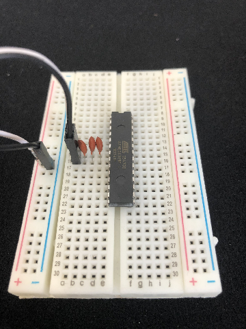
Connect VCC and GND with pin number 7 and 8.
Add 3x capacitors(104) in between.
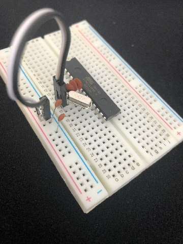
Add the Crystal between pin 9 and 10, and add 2x capacitors(22) connecting to ground from each of those pins.
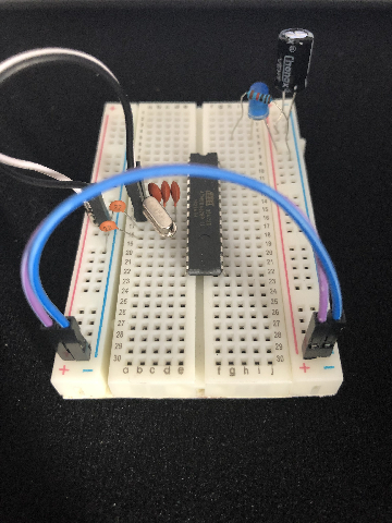
Add the 100uF capacitor between the power and the ground.
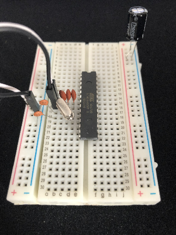
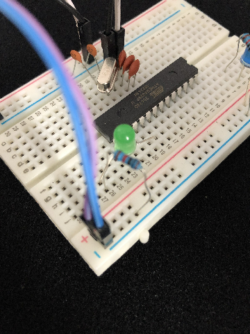
Add LED(blue) to the power, connect it with a 220 Ohms resistor which goes to the ground.
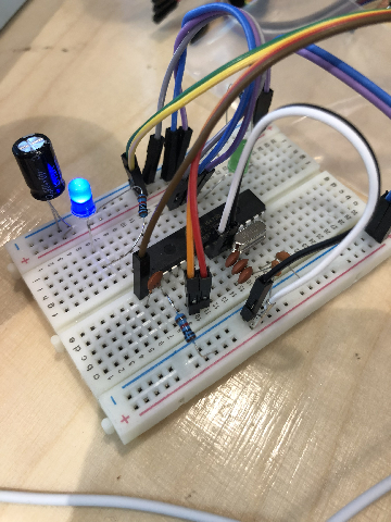
Add power and ground wires at the bottom of the board connecting each rail.
Connect the another LED left and a 220 Ohms resistor with pin 19 and to the ground. The longer leg of the LED connects to pin 19.
Connect ground(pin 22) with ground and pin 21, 20 to the power.
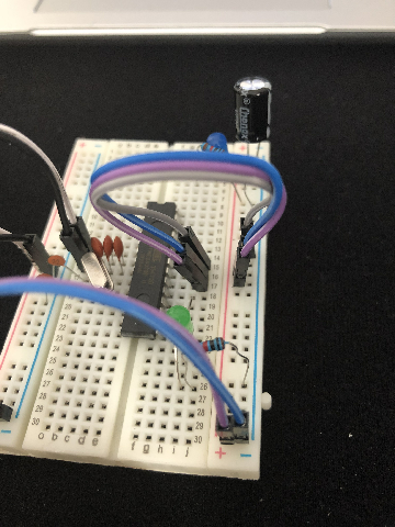
Finally, add the 10k Ohms resistor to the reset and the power, and a capacitor(104) for later use.
Connect the board with our FabISP to the computer, open Arduino, and burn bootloader.(no photos)
Connect this to your board, but you don’t need to connect CTS. Connect it to your computer.
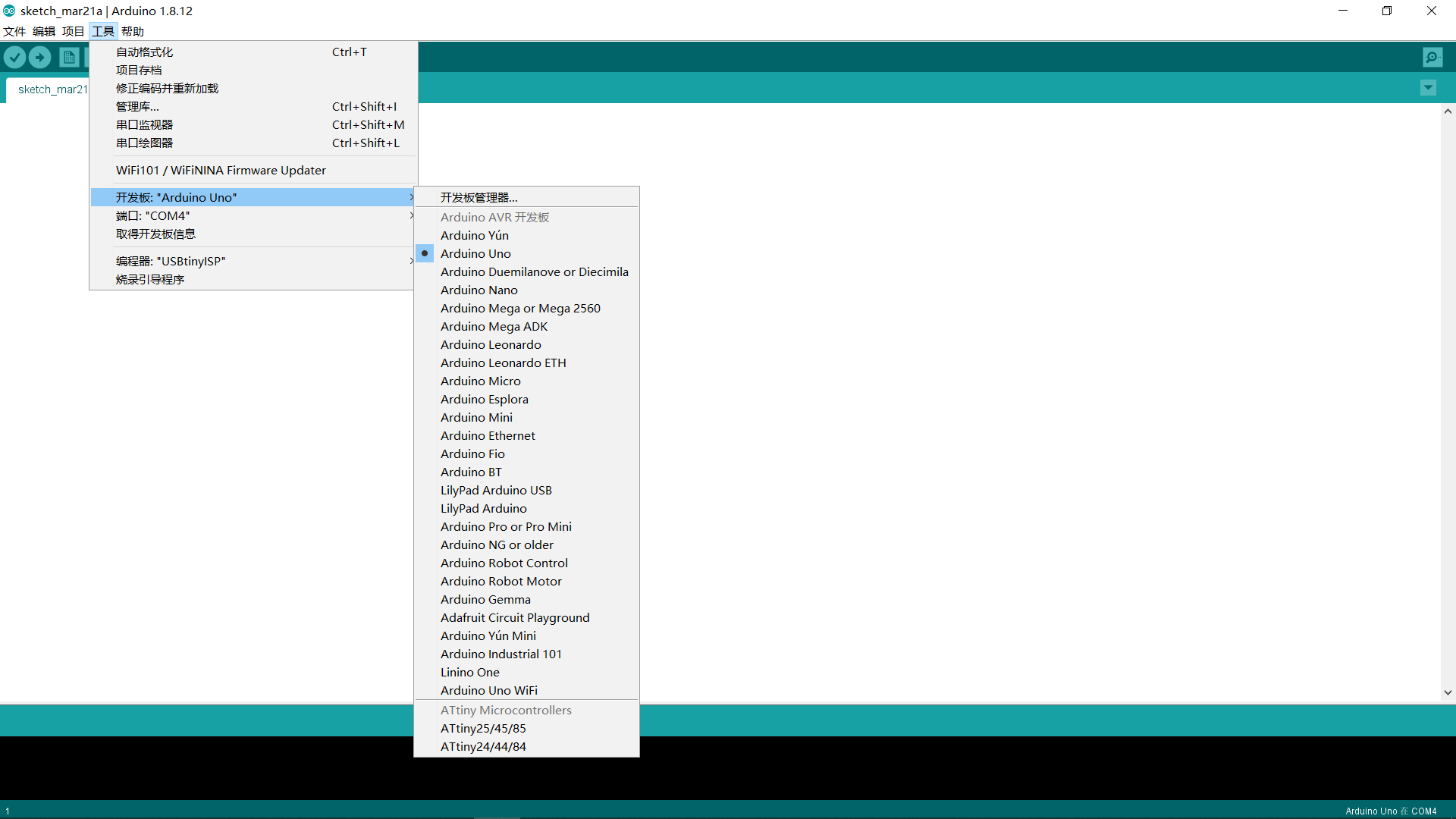
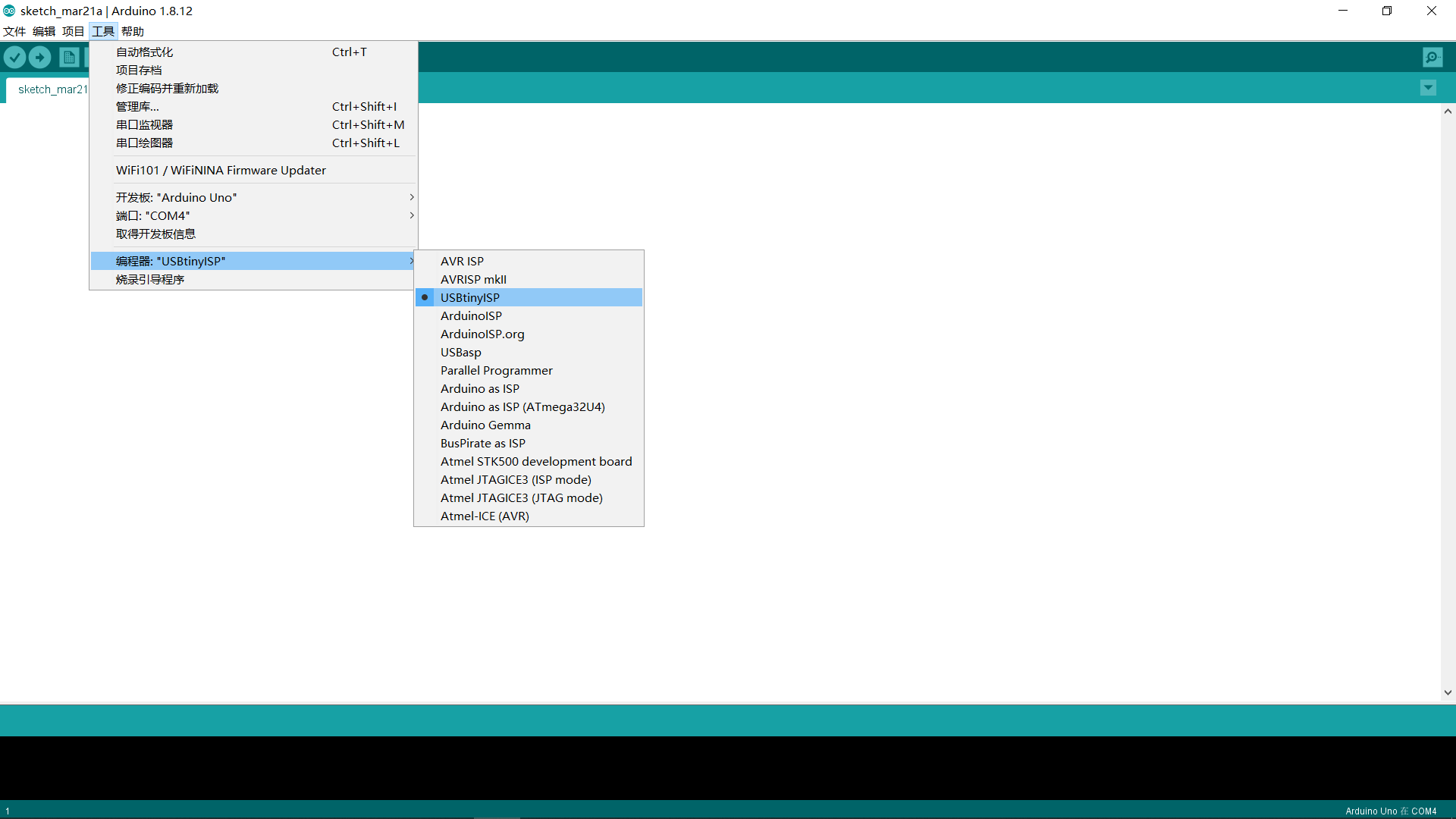
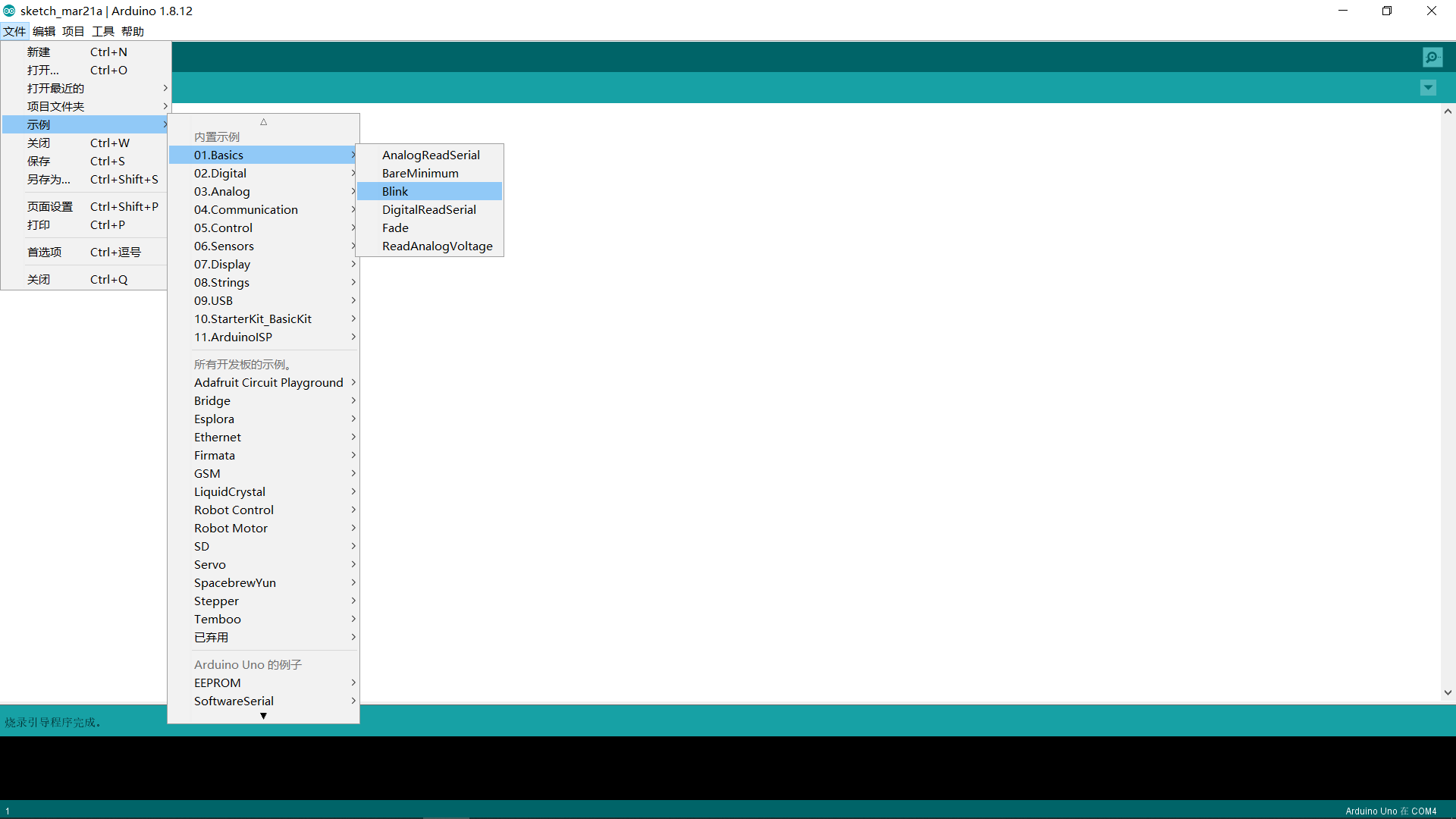
I first try to upload the blink program in Arduino. So I set my Arduino as below.
Open blink program.
Click upload.
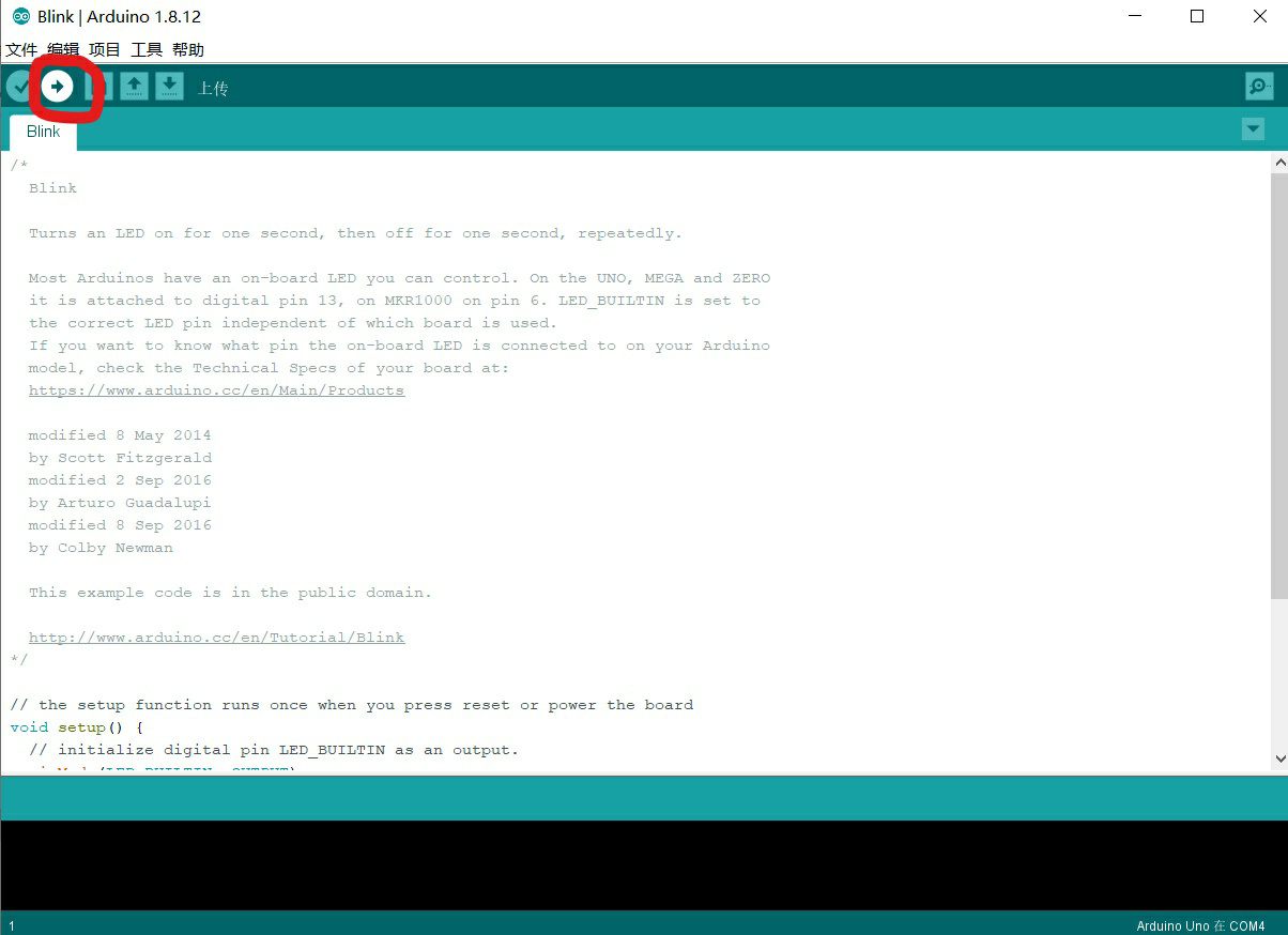
And it works.