week9
10.Input Devices
Objevtive:
Measure something: add a sensor to a microcontroller board that you have designed and read it.
___________________________________________________________________________
I decide to make a new simple board for this week. (image below) I connect 6 pin headers on each side of the microcontroller. In this way, I can have more VCC and GND, and connect more sensors I want.
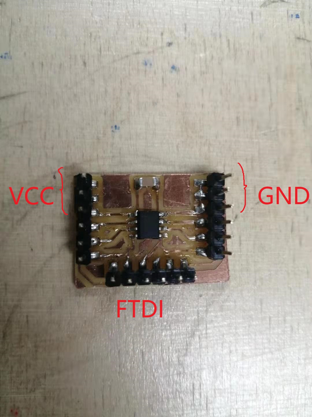
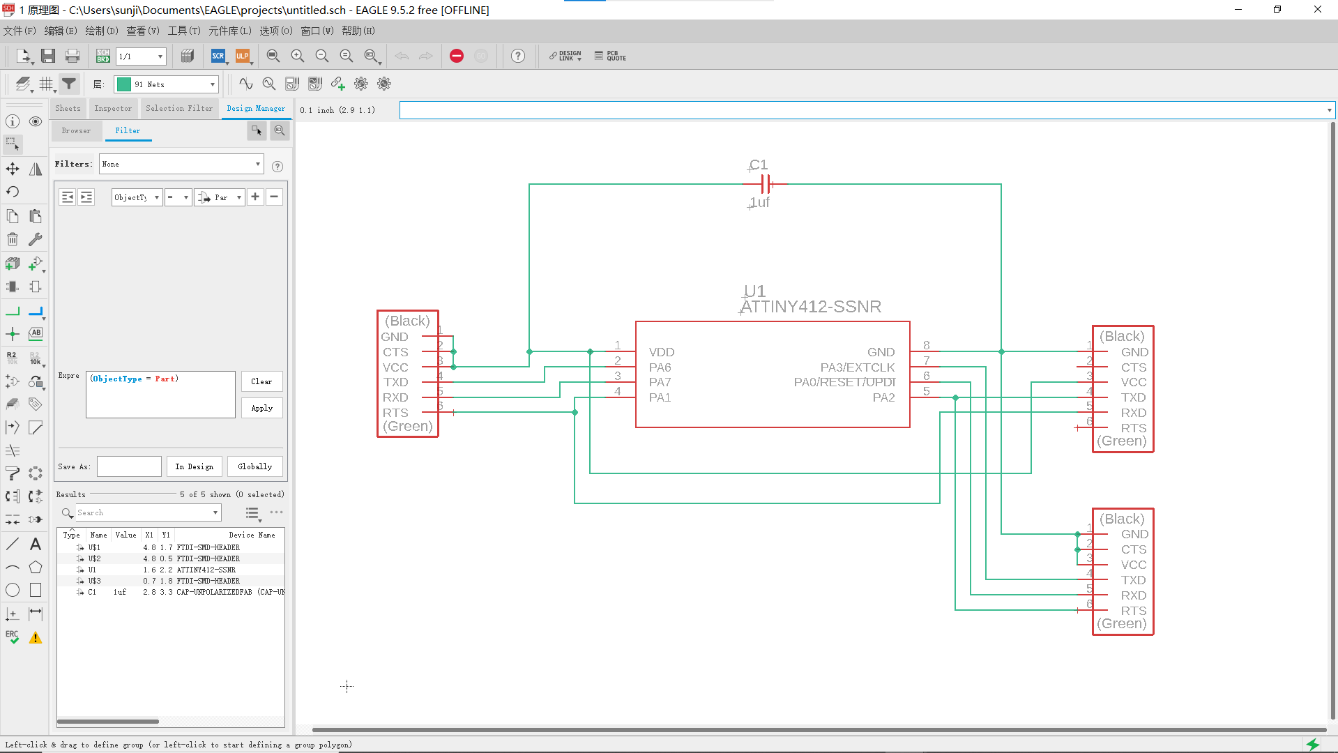
As you can see, when I design the schematic of the board, I use the FTDI part for all my pins only for convenience.
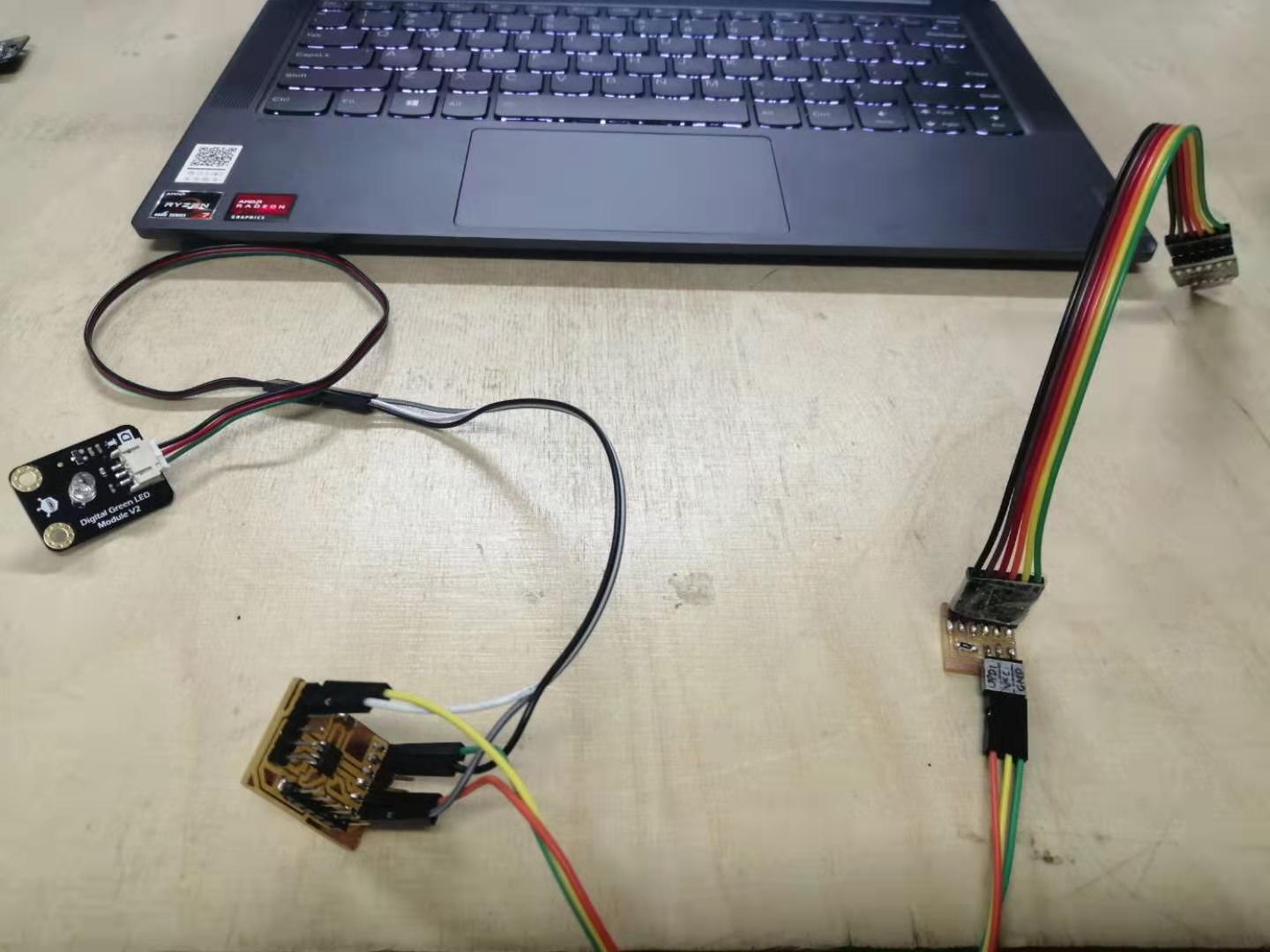
The rest of the process is same as we do the hello world board. Then we start to program the board after finish soldering. The software we talk to the board is different from that of we use for Attiny44. We use pyupdi instead of avrdude to program Attiny412. We know that from embedded programming week. The overall connection is shown below.
I want to use Arduino as toolchain, because it’s the easiest way. I find Adrian from Fablab Leon’s tutorial very helpful and detailed, so I follow his instructions to set up my toolchain in Arduino. But when I connect my board to the computer, I can’t find the port.
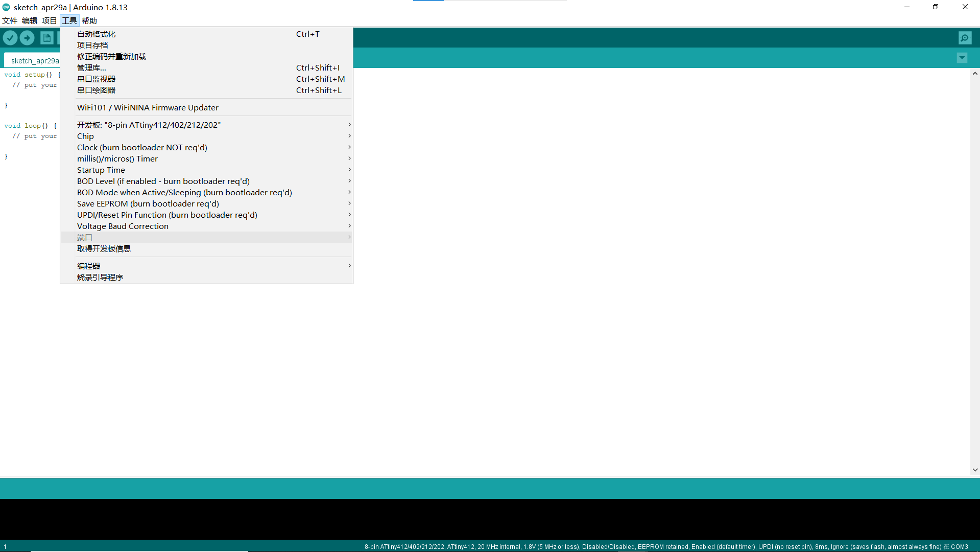
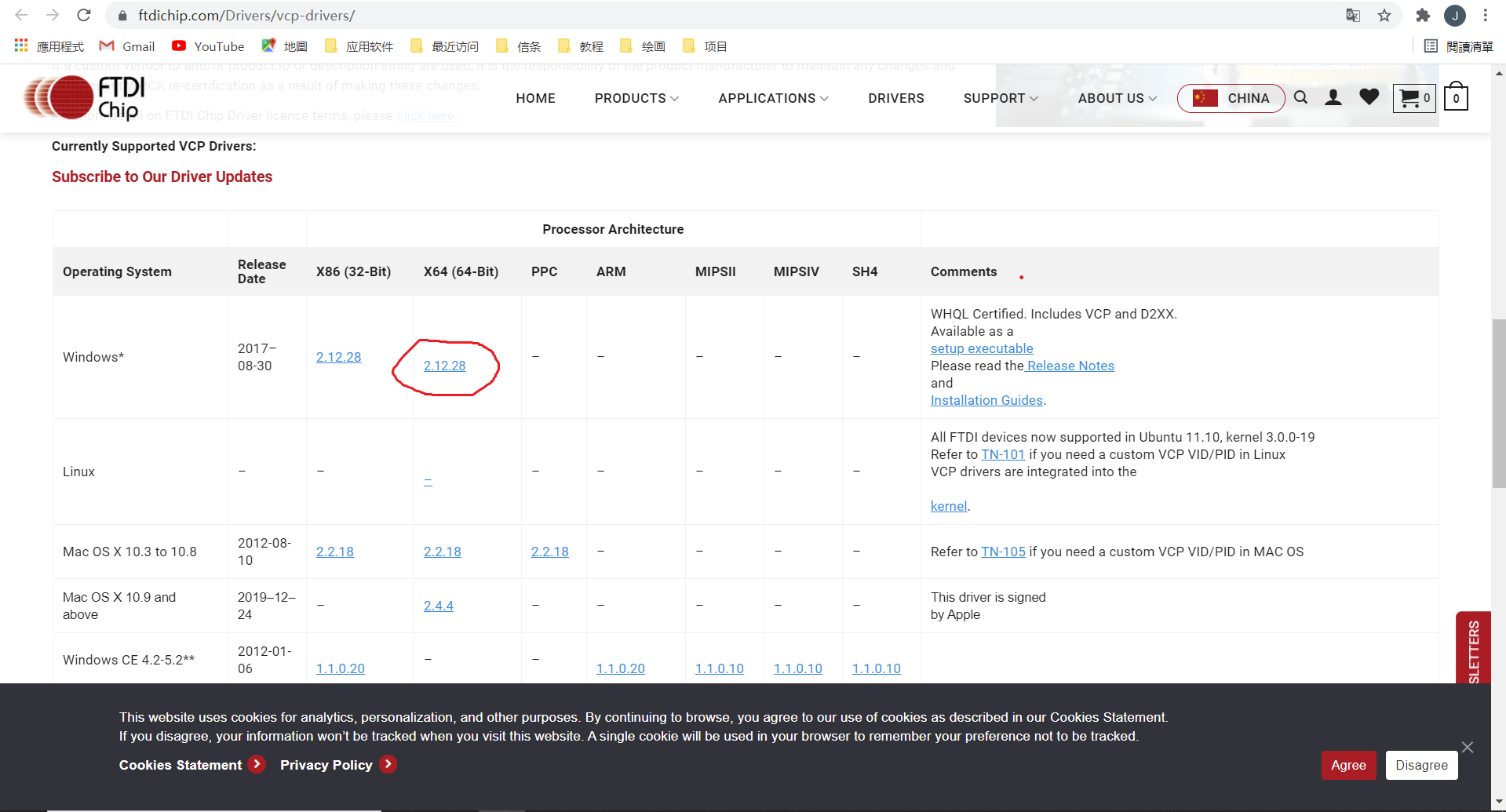
I updated several drivers, and it still doesn’t work. Later I was told to download the driver in this page (image below), and this time it works. Maybe it’s because I’m using a new computer. I totally forgot I have installed it in my old computer.
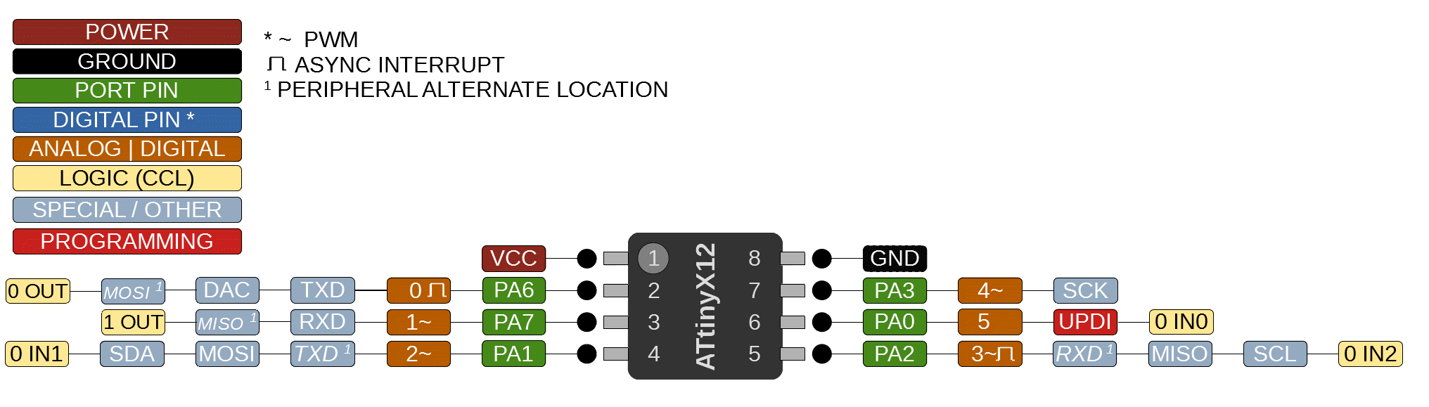
First of all, I try to upload the very basic blink code. I face several mistakes and difficulties. Once, I restart my computer and it works. Sometimes, restarting computer may help if you had turned on your computer all night. I also try out many other sensors. For example, read a button from a serial monitor. The first mistake is I forgot to add Serial.swap() function in the code. Because, as you can see in the schematic, for FTDI, I connect RX, TX with pin 4 and 5, not 2 and 3, which are the default pins for RX, TX. (see the image below) We use pin 4 and 5, because it’s easier when we route the trace out of the board.
Another mistake is when you want to read the data coming from the sensor through serial monitor, you have to take off the serial updi board, and connect the board directly through FTDI. Otherwise the data won’t show up, because the updi board is a one way connection just to upload the program. But when you want the board to talk back, you use FTDI cable directly.
File: