Assignment 2
Week 4 is on Electronic Production. There are 2 assignments; namely:
This website contains the documentation and write-up for the Group Assignment to characterize our StepCraft CNC machine.

Characterization Process
Step 1: Preparing the Test file in machine readable gcode format
The raw test file, linetest.png, is downloaded from the fab academy site on electronics production. The numbers shown are in inches. The smallest width is 1 mil = 0.001 inch.

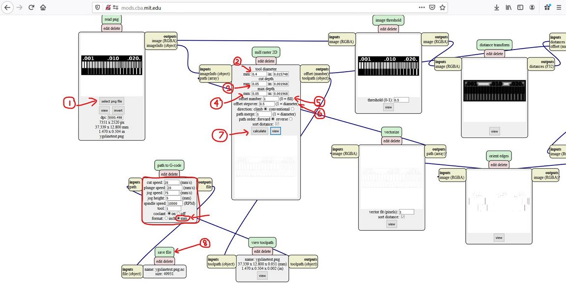
The raw file is then imported to the mods from http://mods.cba.mit.edu.
In the mods page, the png file can be converted into .ns
file which is the Gcode necessary for the CNC machine to
execute the milling process. The steps done in the mods
are shown below.
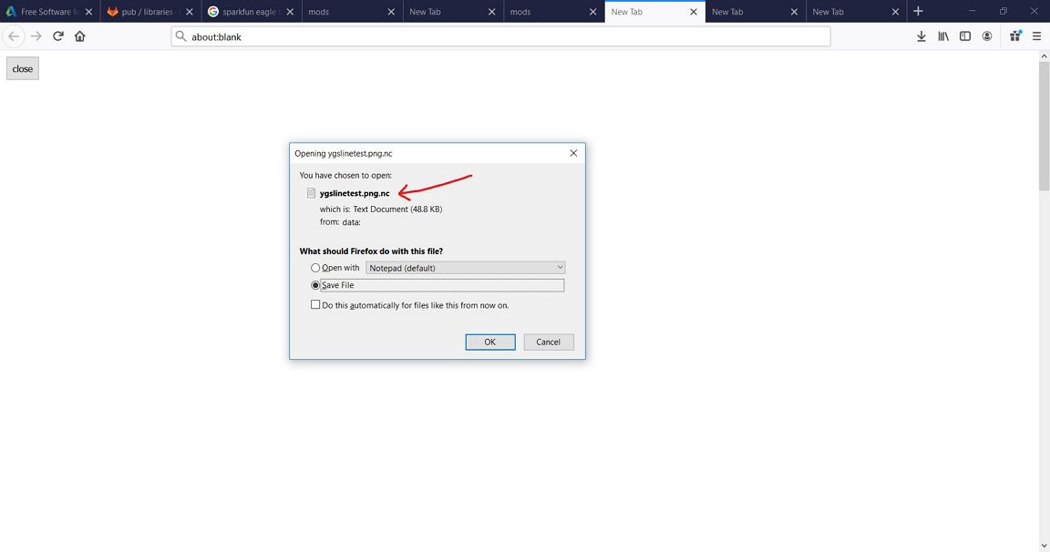
The gcode (.ns file) is then saved in local.
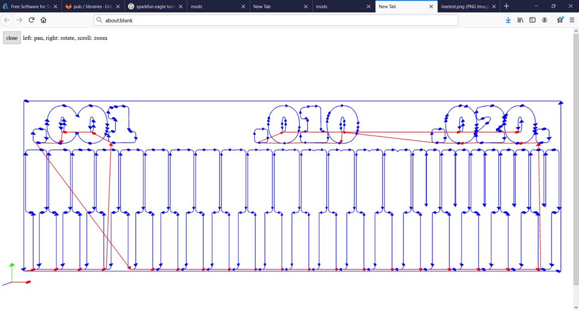
The resulted Gcode can be viewed in the mods too as shown below:
Step 2: Pre-Milling
Check with CAMotics
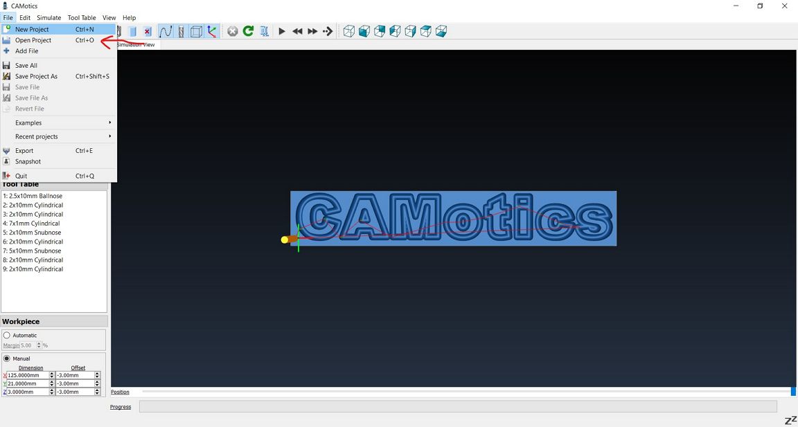
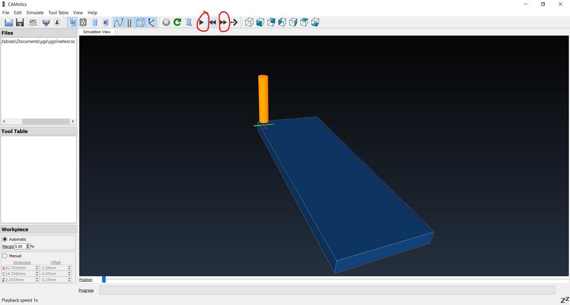
Before milling, it is good practice to perform a simulation to ensure that everything is done correctly.
For this the CAMotics software can be used. The steps are
shown below:
Step 3: Preparing the StepCraft CNC machine
After the simulation is done, the next step is to prepare the
CNC machine.
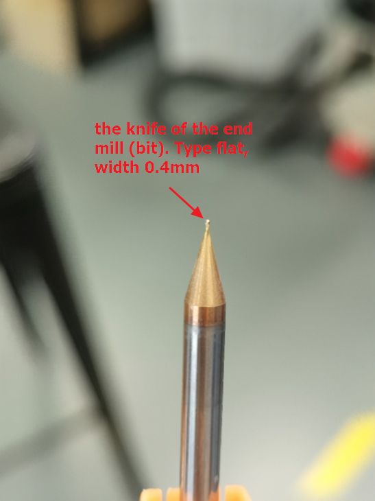
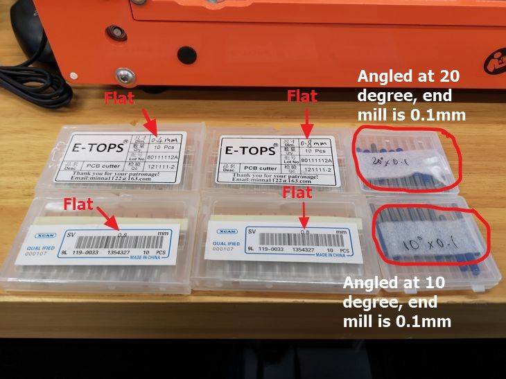
For milling (etching) the trace, 0.4 mm flat end drill
bit is used.
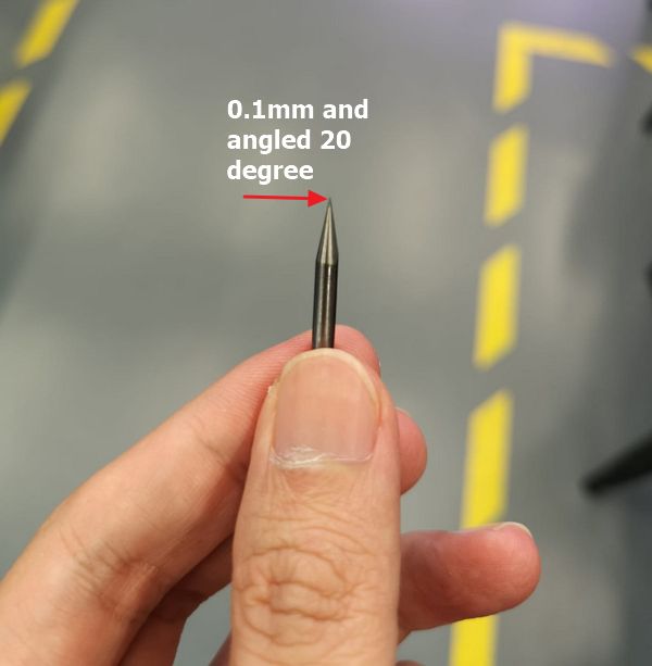
In general, there are 2 types of drill bitss: flat and
angled. The flat will produce consistent vertical depth
cut similar to the width of the end mill, while the
angled type will produce the same width as the drill bit
at the bottom while at the top surface, the dimensions
will be larger depending on the angle and depth of cut.

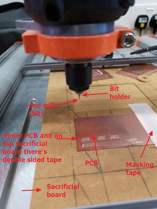
The setup of the CNC machine and PCB board is summarised in
the photo below.
Step 4: Preparing the software to perform the
operation
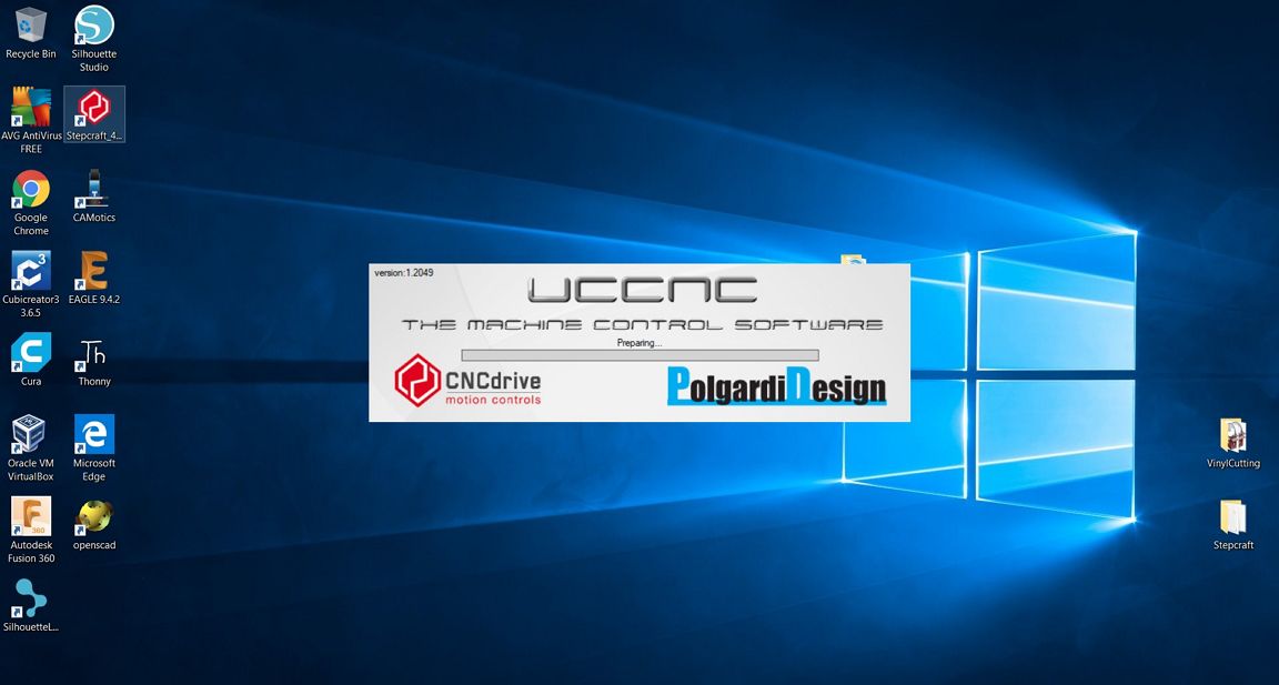
After installing the drill bit, the next step is to
prepare the software. StepCraft uses the UNCNC
software. The programme is started from Windows
Desktop
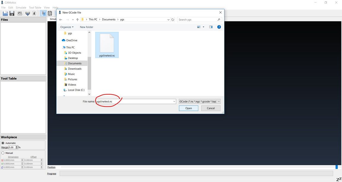
After initialization is completed, the required
gcode file (*.nc) is loaded
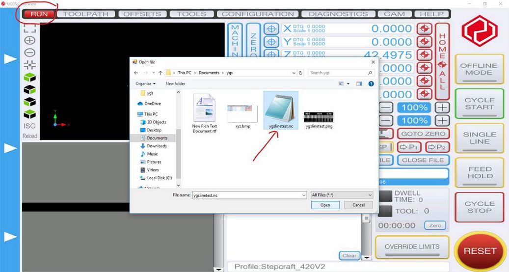
Gcode file loaded on the screen
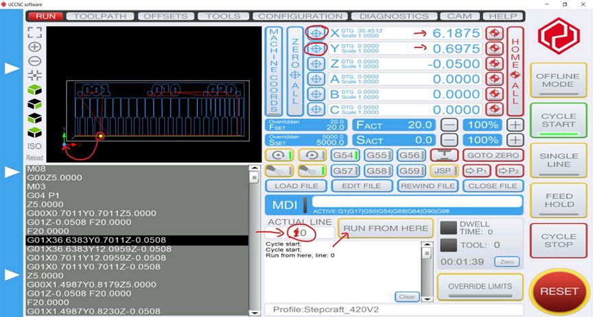
The next step is to set the drill position to the desired position (indicated by the Yellow dot on the screen). The X and Y positions are set by moving the drill to the desired starting point followed by clicking the X and Y zero buttons (circled in red above).
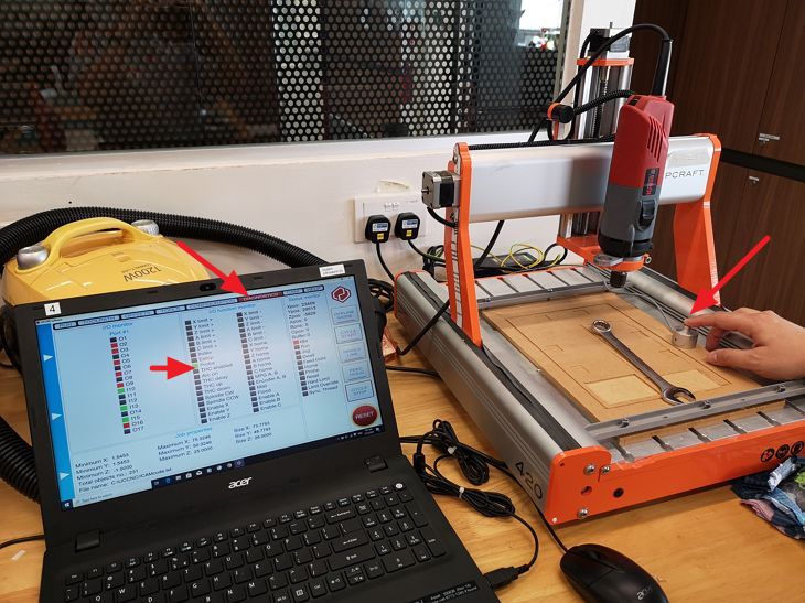
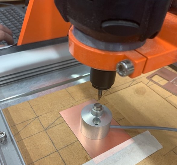
For the Z-direction, the touch sensor probe is used. The diagnostic tab is first activated to check if the probe is connected and operating properly before the calibration in the z-direction is carried out.
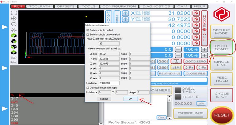
Once everything is set, the drill is switch on and the milling operation is started by clicking on the "Cycle Start" button twice.
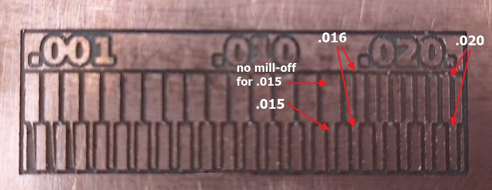
Going from right ot left, the air-gap and the trace were both visible and well defined from 0.02 inches to 0.016 inches. For 0.015 inch, the trace was nicely cut but the air-gap is completely missing. The limit of the CNC machine using 0.4 mm flat end drill bit is hence 0.016 inches or 0.4064 mm, which is the same as the diameter of the drilling bit.
IMPORTANT NOTES
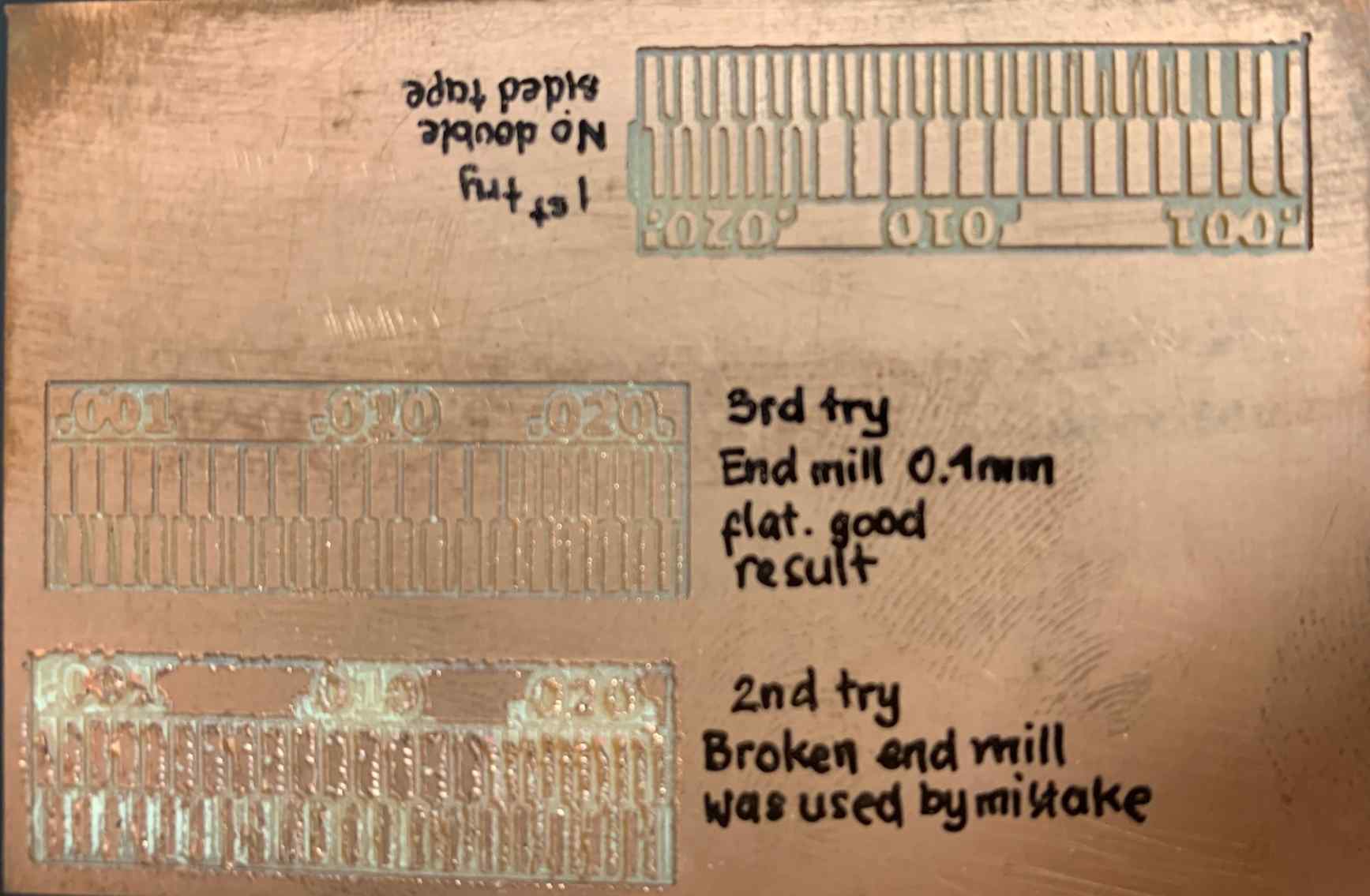
In total, our group made three attempts before getting it right. From this exercise, we learn 2 important lessons:
1. Secure the PCB boards firmly
It is important to use engraved sacrificial board (similar dimension, w, l, h, to standard PCB board) and double sided tape in between the PCB and the sacrificial board. These will make sure the PCB board does not shift still during milling. On our first attempt, the double sided tape was not attached, hence the result were very rough as shown below.

2. Always inspect the condition of the drill bit
carefully before use