Exercise 11. 🔊📱 Output Devices 🛵 💻 🚿
At the end of this exercise, I should be able to:
1. Measure the power consumption of an output device.
2. Design, mill, stuff and program a circuit board for an output device.
3. Add an ouput device (motor, display, speaker, solid-state-relay etc) to a microcontroller board you have designed above.
4. Demonstrate and document workflows used in controlling an output device with MCU board that I have designed.
In exercise 9, I have done input devices and in this exercise I will do output devices. The differences between these two are:
1. Input devices send information to a microcontroller (MCU) for processsing, while output devices receive information from microcontroller (MCU) and display it or used it to perform action according to its function and the MCU program.
In the context of my exercise 9, the input device is the temperature sensor DS18B20 and the output device is LCD display connected to I2C board.
Below is a more elaborative explanation on the input devices vs output devices.
https://www.computerhope.com/issues/ch001355.htm.
📱Measure the power consumption of an ouput device (Group assignment)
For this exercise, we decided to measure the power consumption of a brushless DC motor.
This work is done by Ting Kok Eng and Noel Kristian.
The details of the steps can be seen HERE.
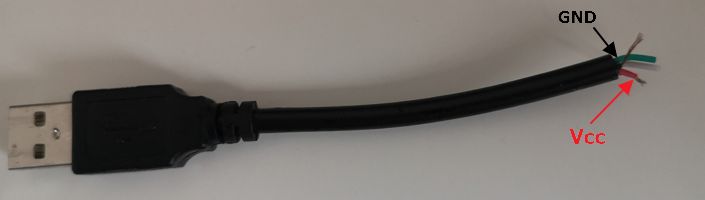
Since Singapore Polytechnic Fab Lab is closed due to the COVID 19, for the appropriate power source for this motor we have to figure it out ourselves. In this case, we have to resort to use an USB cable connected to a laptop, hence a 5.05 V (maximum voltage drawn out of USB port) is observed.
To use the USB cable plugged to laptop/PC as power supply, the cable must be cut off and use the Vcc (red wire) and GND (black wire) as the connection.
Add an output device to a microcontroller board you have designed (individual assignment)🛵 💻 🚿
Since SP Fab Lab is closed, I will experiment with ARDUINO UNO board instead of making new board.
I will also attempt to continue using the board that I have designed in week 9 as the board to connect to an ouput device.
Let's start by experimenting to use ARDUINO UNO board first to familiarize myself with output devices and interfacing them to Arduino UNO board.
Experimenting with Stepper Motor 28BYJ-48 with ARDUINO board🛵 💻
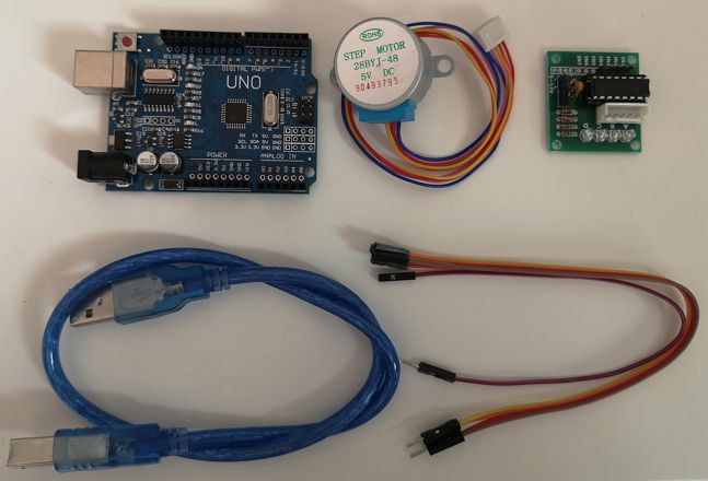
To do this, I use an ARDUINO UNO board, Stepper Motor 28BYJ-48, Stepper motor driver ULN2003, few jumper wires and I refer to this tutorial.
Below are all the components needed for this experiment.
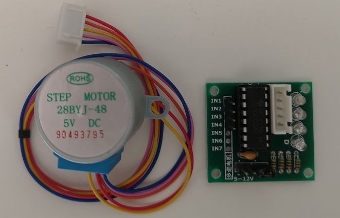
 The data sheet of Step motor 28BYJ-48 can be seen here.
Some key information extracted from the data sheet are:
1. Rated Voltage: 5V
2. Number of phase: 4
3. Speed variation ratio: 1/64
4. Stride angle: 5.625degree/64
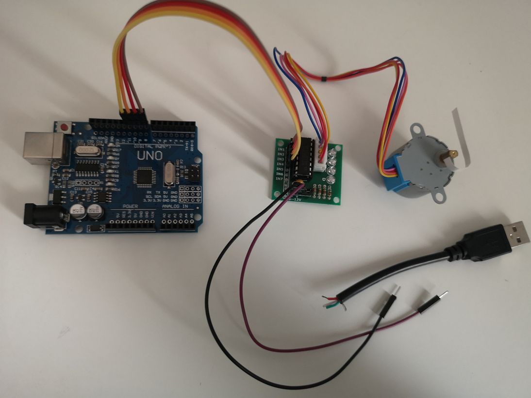
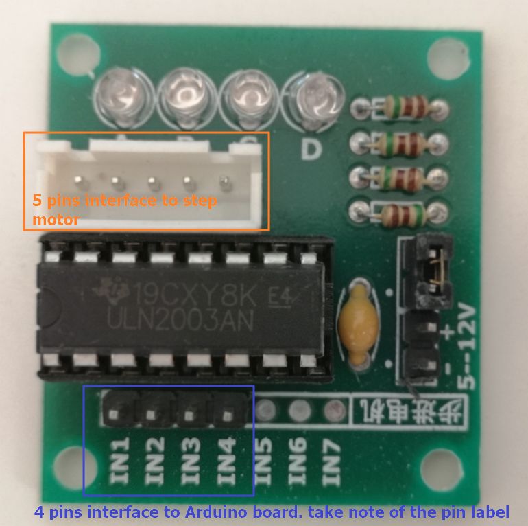
The data sheet of Stepper motor driver ULN2003 can be seen here. ULN2003 BreakOut Connected To Arduino From IN1 - IN4 To D8 - D11 Respectively, as shown below
It is possible to directly power the stepper motor from the 5 V output of the Arduino. This however, is not recommended. When the stepper motor draws too much current, it can damage the Arduino.
I also found that when powering the Arduino with USB power only, I would get inconsistent behaviour and bad performance of the stepper motor.
However due to no access to Fab lab during this Circuit Breaker period, I need to be creative on how to power the stepper motor.
Hence to power the motor, I will use USB port connected directly to the motor. From the group assignment, it can be seen that the voltage drawn out from the USB port of my laptop is 5.05V. While the max. current drawn out of USB port is 500mA.
After uploading the code to Arduino board, I also need to power the Arduino, in this case using a USB type-B cable.
In this video, it can be seen that the stepper motor works fine.
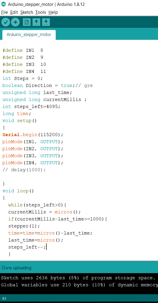
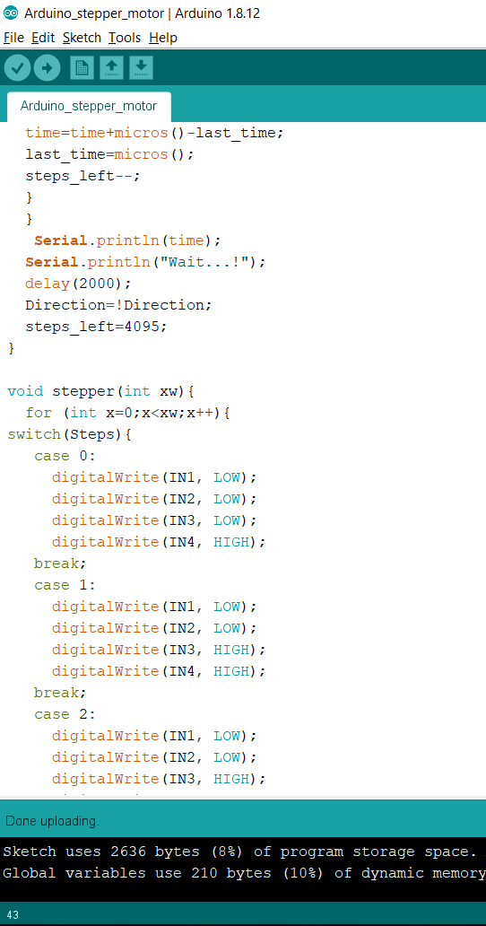
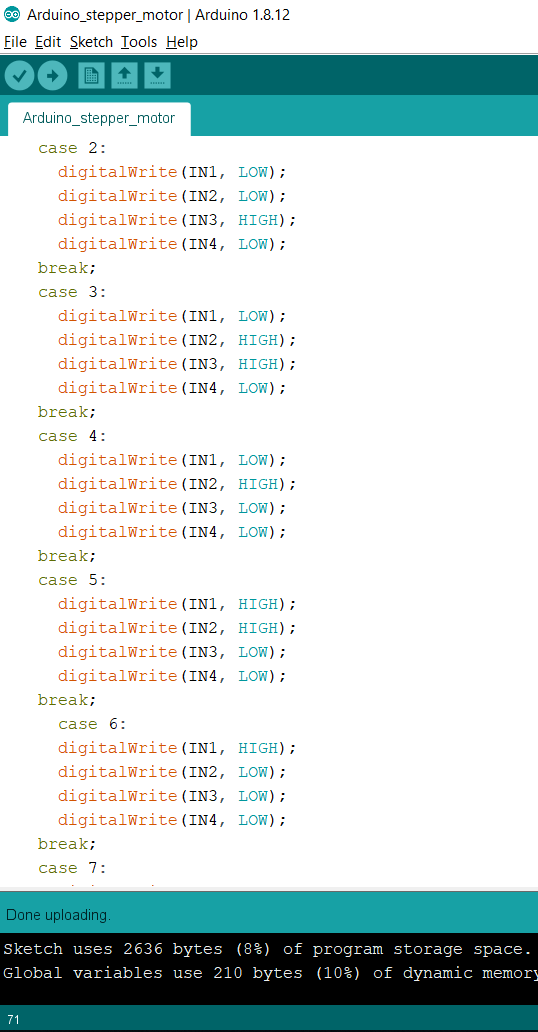
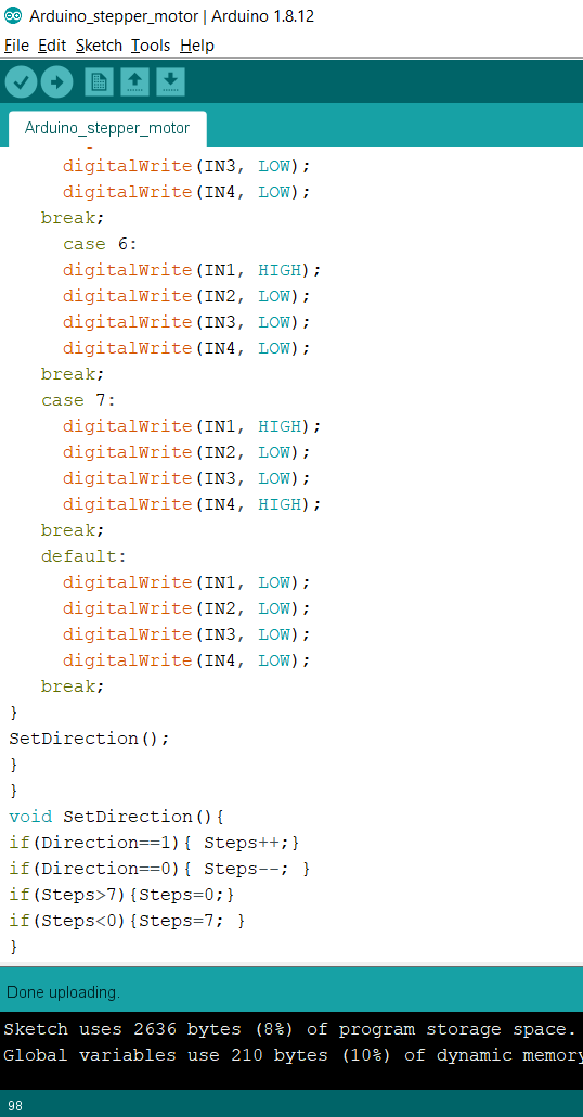
I upload the following example code to my Arduino using the Arduino IDE.
This code allows the motor to rotate clockwise and counter clockwise after one full rotation.
I also tried to measure the current of the stepper motor w/o load as shown below.
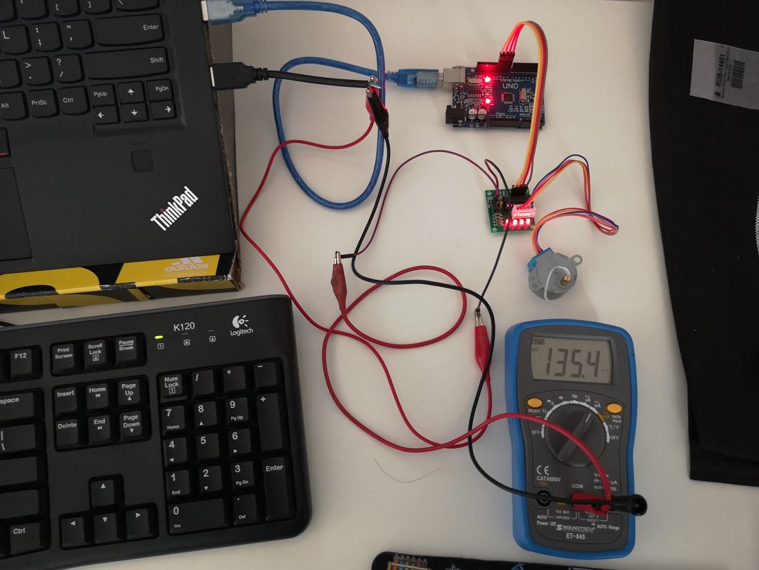
It can be seen that the current was 135mA. But when I observed the full cycle of clockwise and counterclockwise rotation, there were some moments when the motor was idle and registered high current of around 220 mA as seen in the video below. Since the voltage from USB port is 5 V, with this the power consumption ranges from 675 mWatts to 1100 mWatts.
I am still figuring it out on why the current consumption were behaving in that manner.
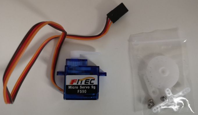
Experimenting with Servo Motor FS90 with ARDUINO board🛵 💻
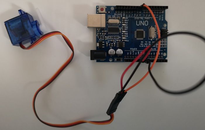
To do this, I use an ARDUINO UNO board, FEETEC Micro Servo 9g FS90 Servo Motor, few jumper wires and I refer to this tutorial.
 The data sheet of FEETEC Micro Servo 9g FS90 Servo Motor can be seen here.
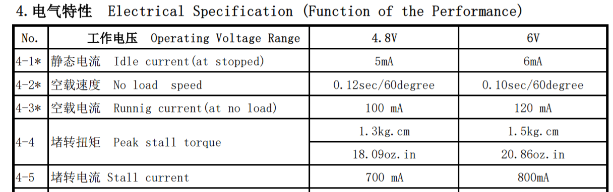
Some key information extracted from the data sheet are below:
The connection between the Servo motor FS90 and Arduino board is below:
The power wire is red, and should be connected to the 5V pin on the Arduino board.
The ground wire is brown and should be connected to a ground pin on the Arduino board.
The signal pin is orange should be connected to one of the digital pin on the Arduino board (in the example below is connected to pin 9)
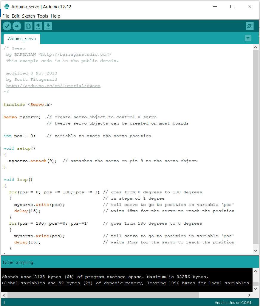
I upload the following code to my Arduino using the Arduino IDE.
This code allows the motor to rotate clockwise (0 degree to 180 degree) and followed with counter clockwise (180 degree to 0 degree.
In this video, it can be seen that the servo motor works following the code.
I also measure the current of the servo motor w/o load as shown in the video below:
It can be seen that the current was in the range of 60 mA. With a voltage of 5V from the USB port through the Arduino board, that means the power consumption is 300 mWatts.This value is lower than the data sheet where the running current at no load is 100mA at operating voltage of 4.8 V, hence power consumption is 480 mWatts.
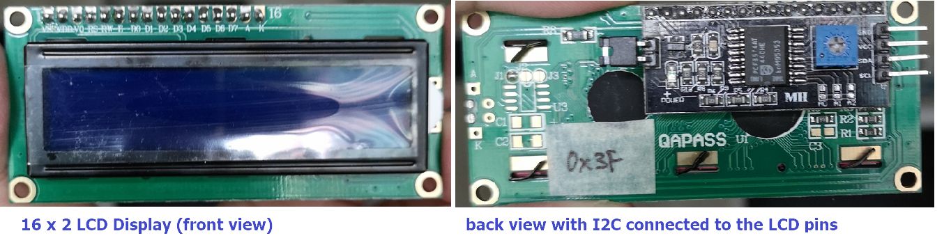
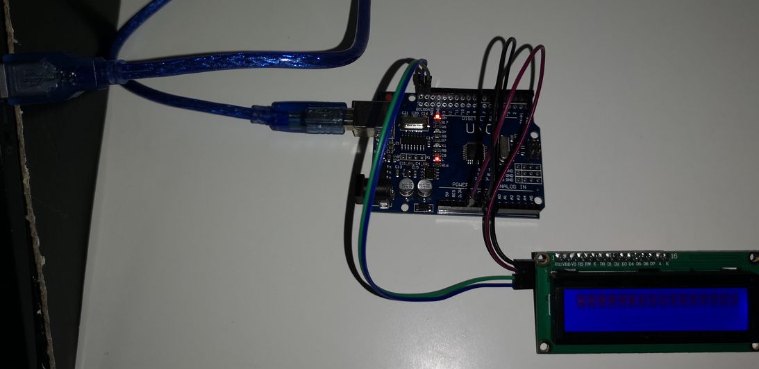
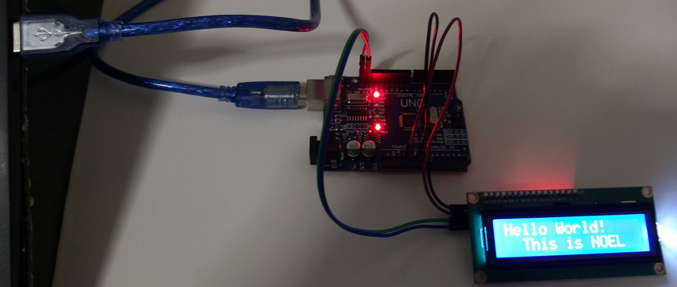
Experimenting with I2C LCD display with ARDUINO board📱💻
To do this, I use an ARDUINO UNO board, I2C board (already connected to 16 x 2 LCD display, 16 x 2 LCD Display, and few jumper wires and I refer to this tutorial.
 Comprehensive explanation on the function of I2C and connecting I2C to Arduino board can be seen below:
https://learn.sparkfun.com/tutorials/i2c/all.
https://howtomechatronics.com/tutorials/arduino/how-i2c-communication-works-and-how-to-use-it-with-arduino/.
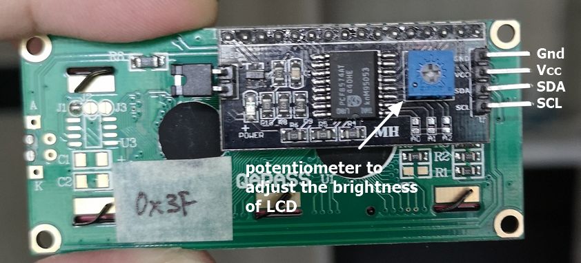
The connection between I2C board and Arduino board is below:
The Gnd pin in I2C should be connected to the Gnd pin on the Arduino board.
The Vcc pin in I2C should be connected to a 5 V pin on the Arduino board.
The SDA pin in I2C should be connected to SDA pin on the Arduino board (next to AREF pin) or to pin A4.
The SCL pin in I2C should be connected to SCLpin on the Arduino board (next to SDA and AREF pin) or to pin A5.
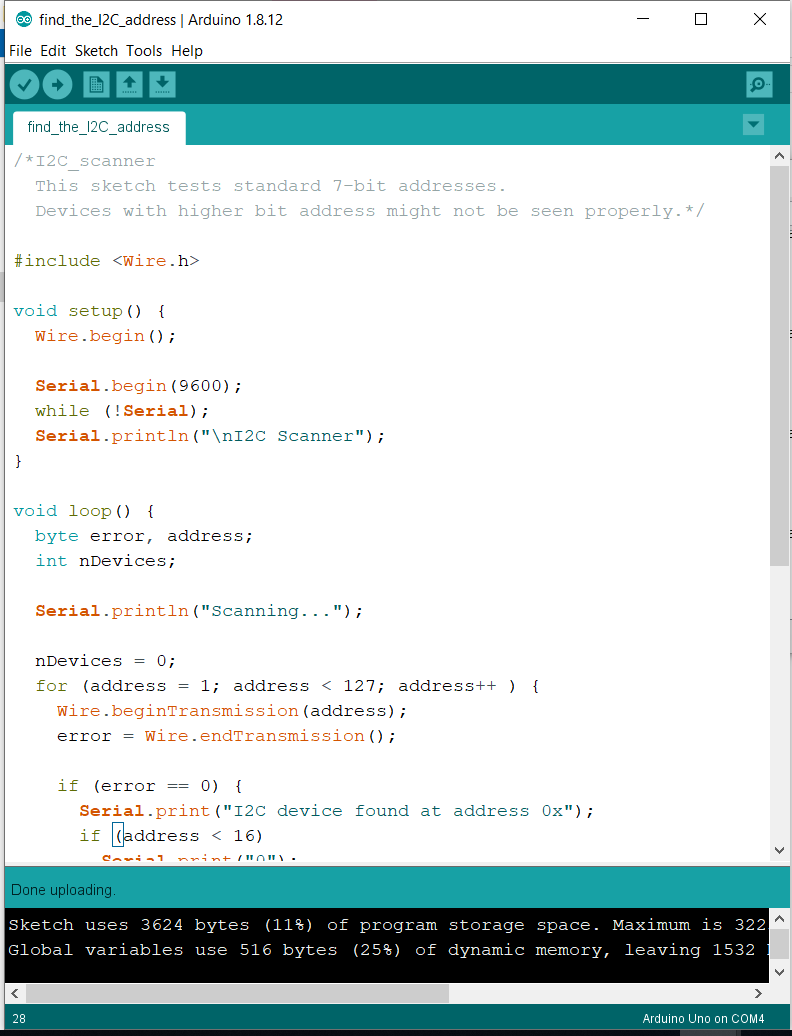
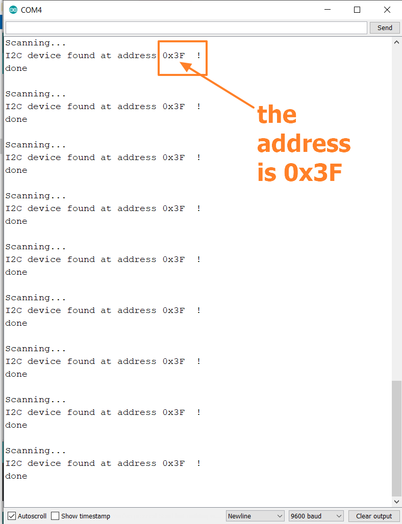
I upload the following code to my Arduino using the Arduino IDE to determine the address of my I2C.

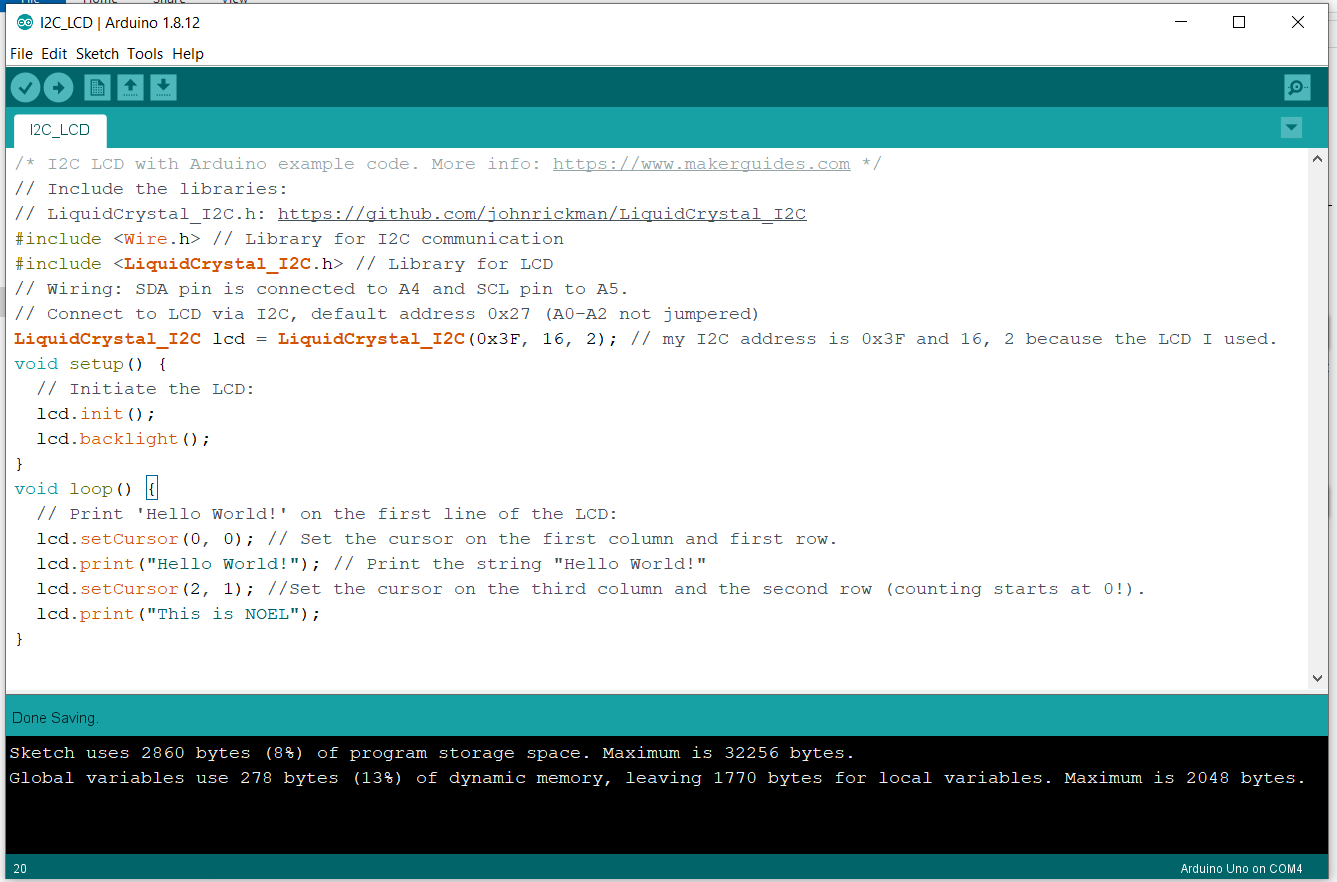
I upload the following code to my Arduino board using the Arduino IDE, but before that I included the LiquidCrystal_I2C Arduino library.
This code will display "Hello World!" on the first row first column and "This is NOEL" on the second row 3rd column.
And the result on the LCD display:
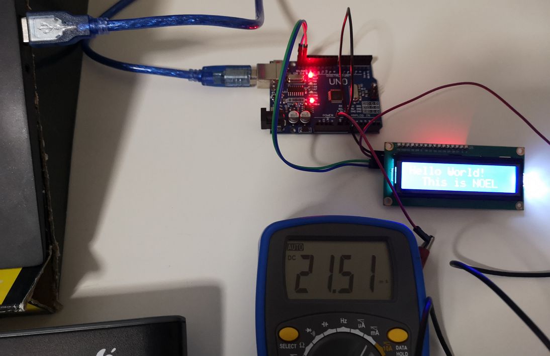
I also measure the current of the I2C with LCD display at this potentiometer setting. The current measured is 22 mA.
Designing my own board for Servo Motor FS90🛵 💻
I use the board that I design for my final project to complete this output device assignment. For the final project, I will be using Servo motor FS90 too.
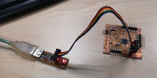
The detail of the board design, production (milling, stuffing) and all the design files can be found in the final project page HERE.
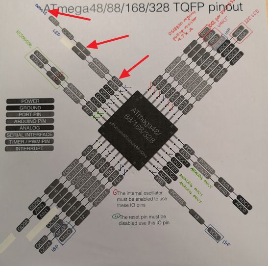
For the Servo motor FS90, I uploaded the below code to my ATMega 328 board.
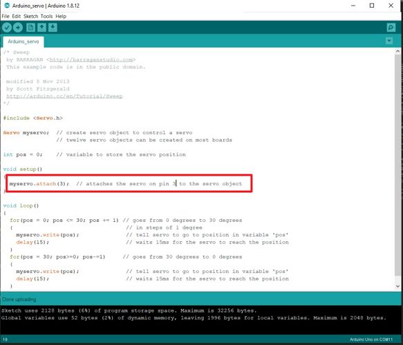
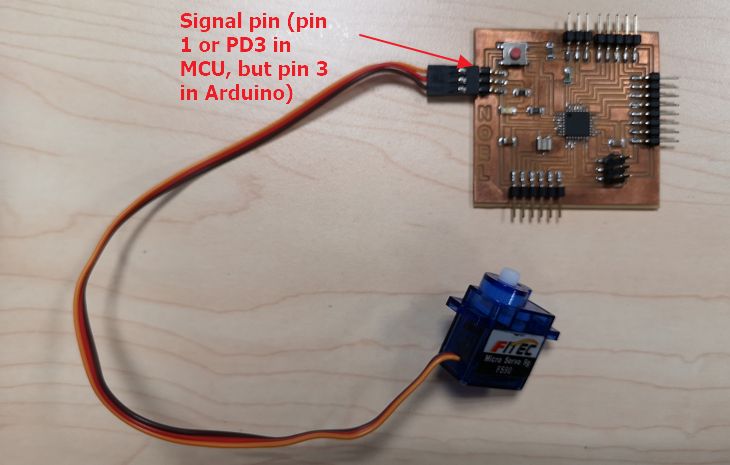
Eventhough my signal pin is pin number 1 (PD3) I used the same pin number as Arduino Pin number (pin 3) because for the programming in Arduino IDE, I will define the ATMega328 board as Arduino UNO.
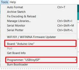
 To upload the program onto the board, I used Arduino IDE and set the board as Arduino UNO and use programmer "USBtinyISP".
to download the .ino code for the servo FS90 for ATMega328 Board.
After uploading the code, I connect the Servo FS90 sensor.
 And below is the video where the servo FS90 is turning from 0 to 30 degree back and forth