Electronics Design
In this page, I will describe the Electronics Designs, production, programming and testing for my final project
Design
I wanted to have 2 servo motors (likely FS90 mini servo), one DS18B20 temperature sensor and LCD panel with I2C board. Optionally, I want to have provision in my board for bluetooth function.
Listing down all the data pins reuired by each of the input/output devices:
1. 2 Servo motor = 2 data pins (I name them SRV1 and SRV2)
2. 1 DS18B20 = 1 data pin (I name it DQ)
3. LCD with I2C board = 2 pins (SDA and SCL)
4. UART serial communication = 2 pins (RX and TX)
5. LED = 1 pin
6. ISP = 4 pins (MISO; MOSI; RST; CLCK)
With all these input/output devices, I will need an MCU with many pin out and reasonable memory space, hence I decided to use ATMega328 as my MCU.
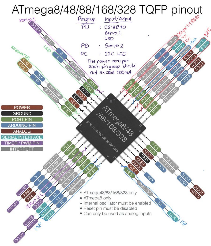 Uisng the above ATMega328P pin drawing, I planned on how I want to make use the pins respectively.
I also consider spreading the input/ouput data pins to various pin group because the recommended power sum for each pin group should not exceed 100 mA.
Using the power measurements that I have done on EXERCISE 11 OUTPUT DEVICE as shown below, I arrange the pins usage:
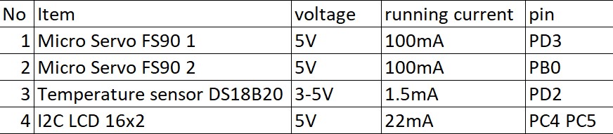 With this arrangement, I will need to use minimum 20 pins out of the 32 pins.
I also use 5 extra pins for future planning when I want to add/modify the protoype.
With this planning, I have more confident to create the schematic drawing in EAGLE. I followed the steps that I have done in EXERCISE 6 ELECTRONICS DESIGN.
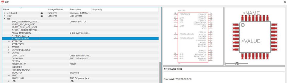
All the components except for the 3, 5, 6 and 8 pin headers are from the Fab library in EAGLE. The new component is the ATMega328 that was added using the ATMega88-thin as shown below.
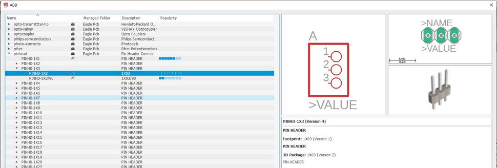
 Whilst for the header pins, they were added from the "pinhead" library as shown below:
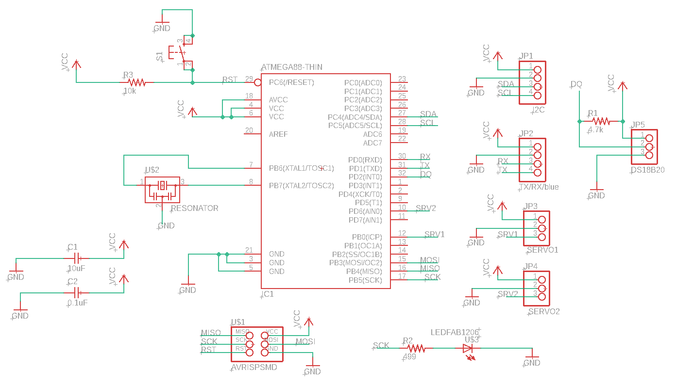
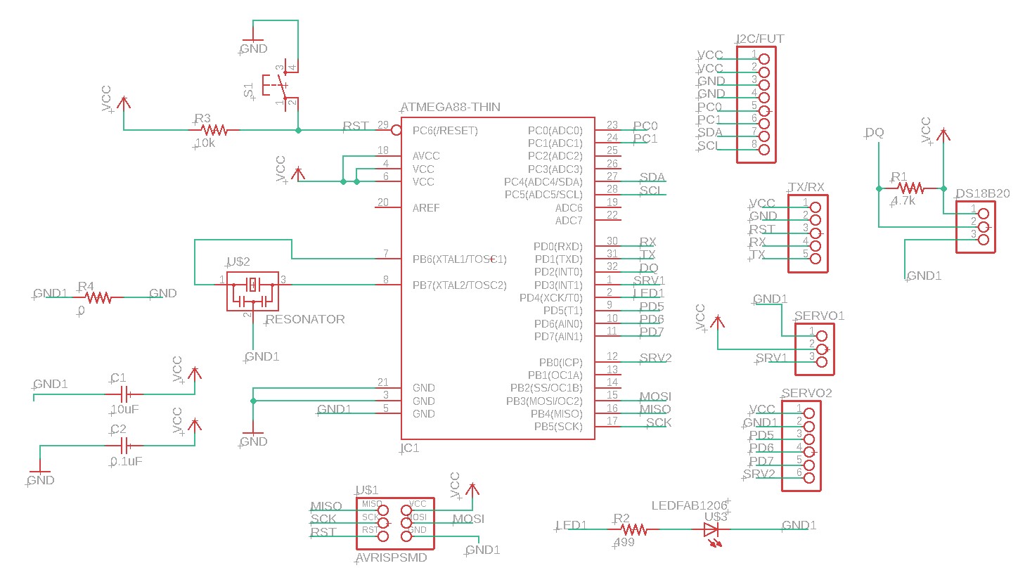
I started to create the schematic using the planning above and below is the schematic result.
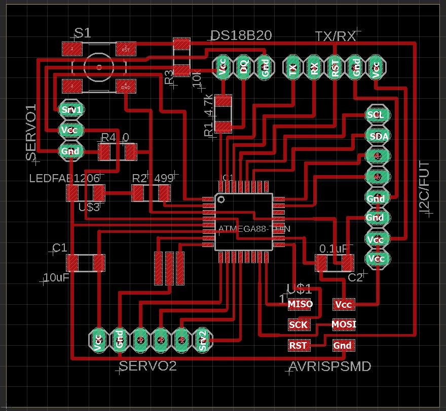
 It seemed that the components are well connected and then I continue to create the board drawing and the result is shown below.
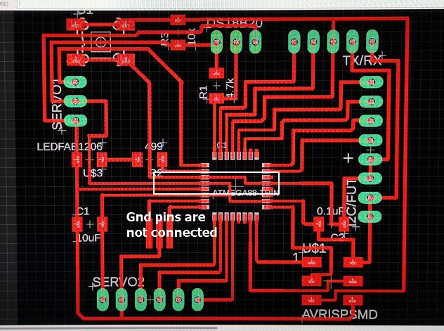 But when I did the ERC in schematic, i realized that the 3 GND pins are not connected.
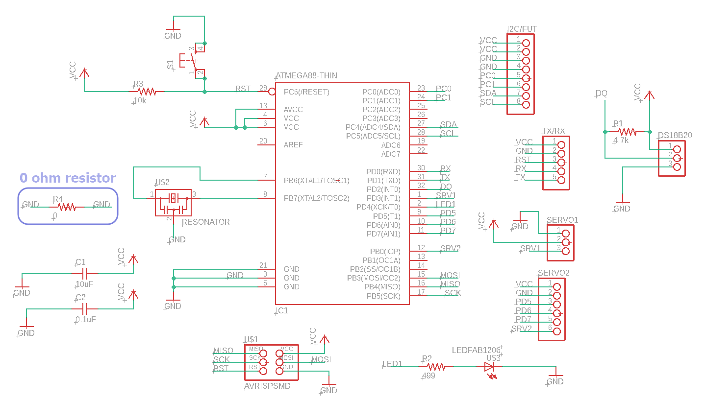
But all the components are already layout nicely as seen in the board drawing and after looking for possibilities, I realized that I need to use a 0 ohm resistor to connect the Gnd pins. Below is the amended schematic and board drawings.
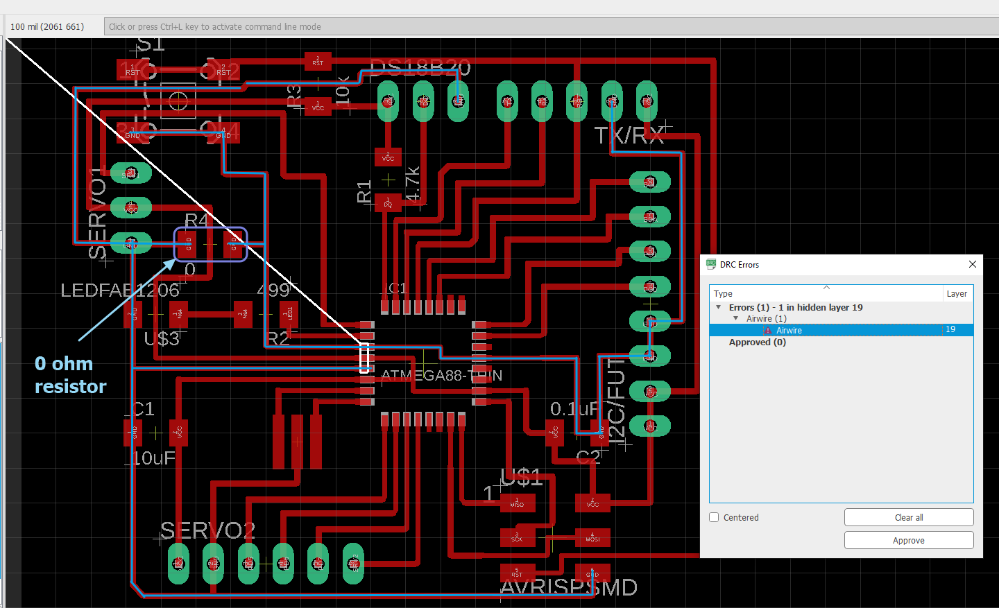 But when I did the DRC in the board, error message appear as shown above.
All 3 ground pins are connected. One of the connection is using 0 ohm resistor but DRC always says there’s airwire indicating the connection using the 0 ohm resistor is not recognized.
I consulted my Fab Lab coach, Mr. Steven and he told me to use different naming for the 2 end of the 0 ohm resistor. In this case I use Gnd and Gnd1. With this small modification, the DRC doesn't show any error message anymore.
Below are the final schematic and board drawings.
to download the EAGLE schematic .sch file
to download the EAGLE board .brd file
I created the .png files for both the traces and the cut and this time I did some modification in the .png files using GIMP whereby I added my name into the board.
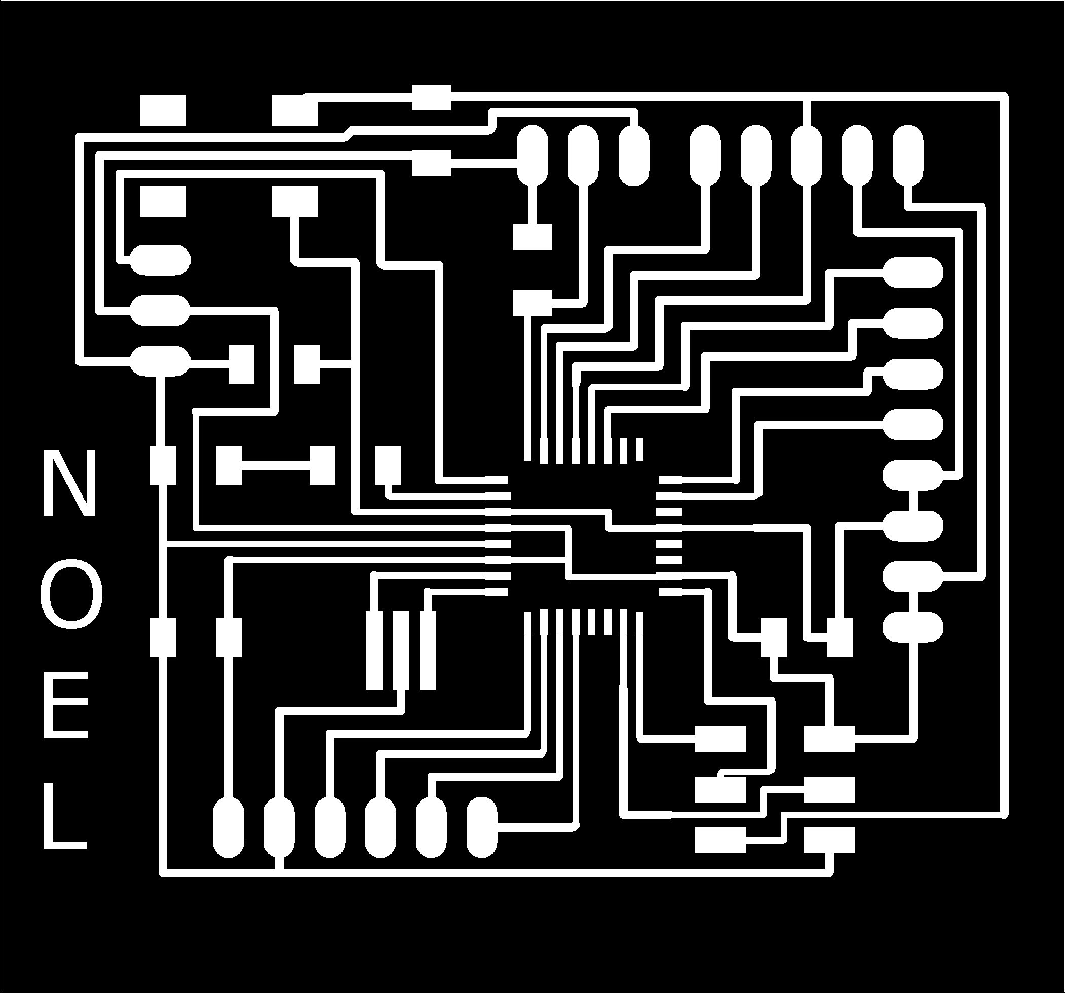
to download the .png file of the traces.
to download the .png file of the board cutout.
Milling and stuffing
After completing the board design, now it is time to mill the board.
To generate the toolpath, i use mods as explained in the EXERCISE 4 and in EXERCISE 6.
This time I wanted to mill 2 boards with different settings, the cut depth and max depth, in mods. In the previous exercises I have always use 0.06 mm as the cut depth and max depth for the traces.
Besides using 0.06mm, I will also mill the traces using 0.03mm for cut depth and max depth. I wanted to try this new setting because I notice that with 0.06 mm cut depth, almost 3x of the copper thickness is milled out, which I think not necessary.
Below are the 2 settings of different depth in mods.
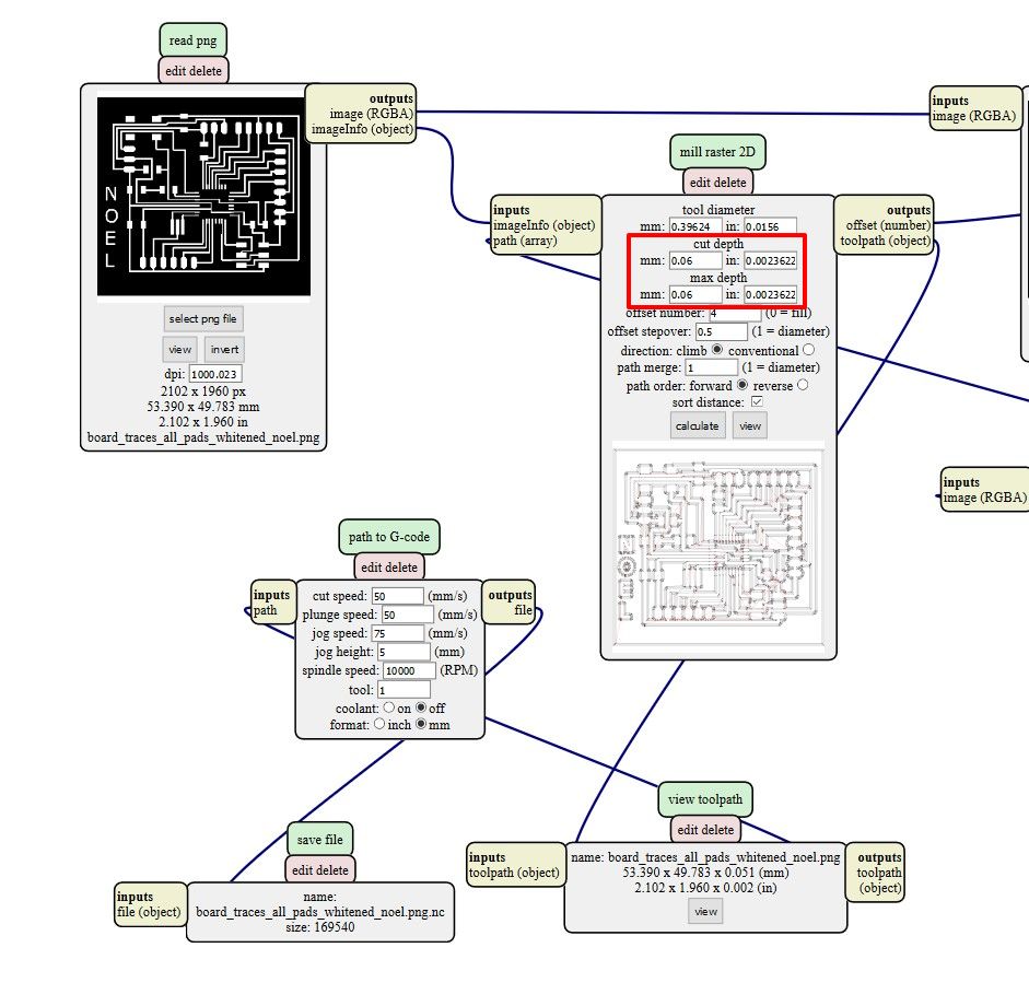
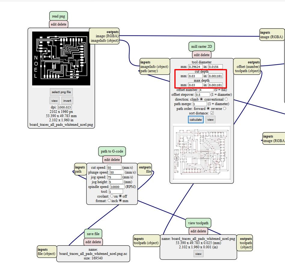
to download the toolpath (g-code) .nc file of the traces using 0.06 mm depth.
to download the toolpath (g-code) .nc file of the traces using 0.03 mm depth.
to download the toolpath (g-code) .nc file of the board cutout.
But when I started to mill using end-mill of V-shape with diameter of 0.1 mm and angle of 10 degree, the milling was unsuccesful because the double sided tape I used to stick the PCB onto the sacrificial board was not strong enough.
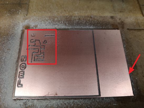 Becasause of that the milling traces were out of line.
With that experience I used a zig-zag double sided tape and now the PCB stuck strongly on the sacrificial board.
Below are the results after milling. The left side is the 0.06mm depth and the right side is the 0.03mm depth.
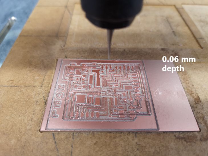
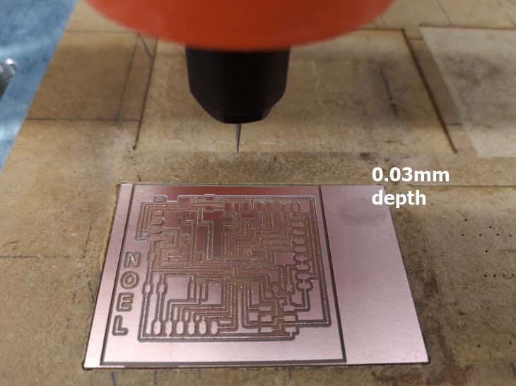
After cleaning the burr using very fine sandpaper and soft painting brush, the 0.06 mm mill showed wider traces width and more narrow gap between traces compared to 0.03 mm.
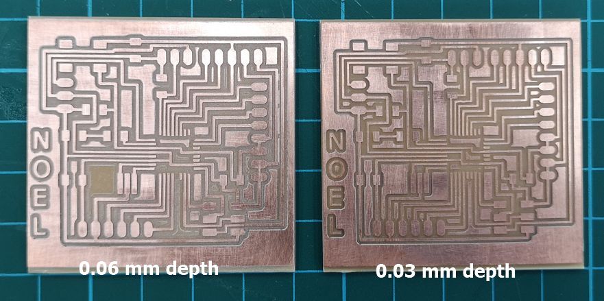 Since, My soldering skills still not good enough, hence I selected the 0.03 mm as the board for stuffing because with bigger gap between traces, there's smaller probability of bridging through careless soldering by a beginner in soldering like me =p.
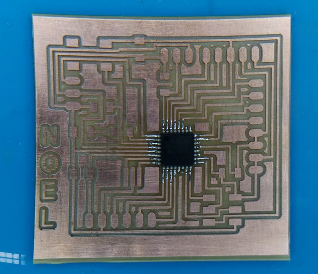
Stuffing was still quite challenging for me. It took 2 days for me to plan, prepare the tools etc. And When I finally able to solder the MCU, I was so happy.
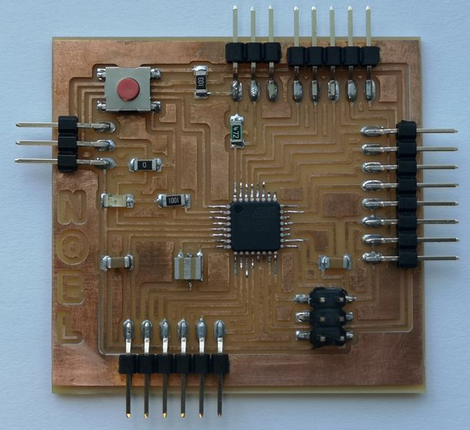
 And when I finally completed the stuffing, I can't stop admiring the final results and also feel proud of my work.
Programming
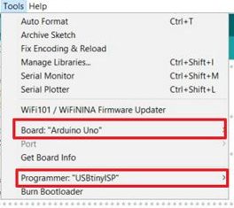
Programming the ATMega328P is straightforward. I use Arduino IDE and set the board as Arduino Uno. Since I am using USBtinyISP as my programmer then I need to select that under the programmer.
 When writing the program, the pin number used must be using ARDUINO pin number.
I program the board to test the ATMEga board with DS18B20 Temperature sensor. The details can be seen in the EXERCISE 9 PAGE .
Below is a short video of the board with DS18B20 sensor measuring 2 different temperature.