Second assignment
Date
29 Jan 2020
Final Project : Faby Robot
Concept
Technology is everywhere in our lives. Kids these days spend most of the time using their electronic devices. They know how to play games, and watch videos before they can even speak properly. It is important to motivate children to become active creators rather than passive users.
I believe every child needs to know the basics of coding to excel in our rapidly changing world. Having children learn coding at a young age prepares them for the future.
For the final project, I decided to make an educational robot for kids called FABY.
What is Faby ?
Faby is a colorful robot that helps kids to learn coding principles and understand the algorithm basics in a fun way. It boosts the child's critical thinking, coding skills and problem solving.
How does it work ?
Kids will create a path that leads faby to the destination by positioning blocks in a correct sequence.
There are 6 blocks, each block is embedded with a radio frequency identification (RFID) card that provides Faby with a unique directional command.
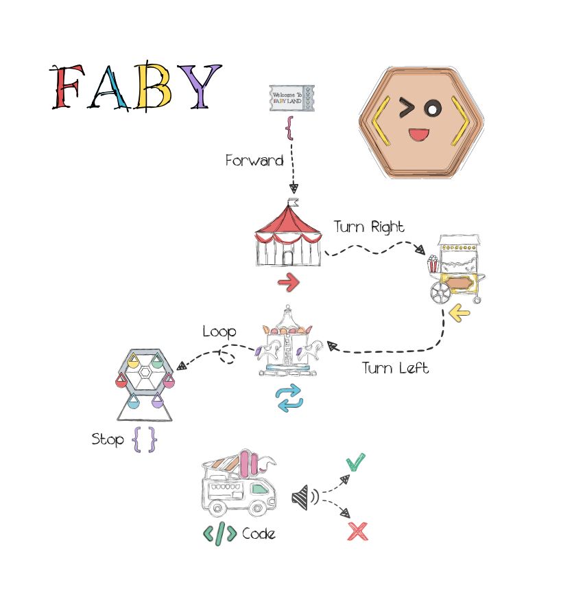
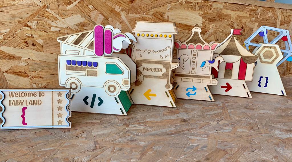
I designed the blocks as an amusement park because it is the happiest place for kids and for me also.
Each block has a specific symbol :
Fabyland Ticket { to Forward
Circus Tent → to Turn Right
Popcorn Cart ← to Turn Left
Carousel ←→ to Repeat Last Command “ Loop”
Ferris wheel {} to Stop
Ice cream truck to Code
There are two ways to play with Faby.
First game : Find the Ferris wheel
Kid will guide Faby to the Ferris wheel which is the final destination by arranging the blocks depending on the right sequence of the symbols.
Second Game : Challenge Faby
The Ice cream truck is the challenge block that includes a special code. The kid needs to identify the code sequence by moving each block in front of the robot. There are three melodies that Faby plays. The first melody plays when the code starts to make the kid pay attention to the robot movements. The second and third melodies reflect the true and false. They work depending on the block that the kid will try to guess and put it in front of Faby.
Project Sketches
I started with a simple sketch on a paper to imagine how the robot will look like. The angle bracket symbol is one of the most famous programming symbols that can be used to include tags or pieces of code. I used it as inspiration for designing the robot shape and reflected the coding concept.
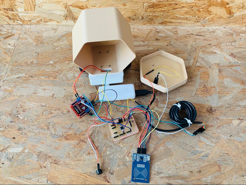
Define the requirements:
Robot chassis x 1
RFID reader x 1
RFID tags x 6
DC gear motor x 2
Buzzer x 1
L298N motor driver x 1
PCB x 1
Wheel x 2
Mini caster wheel x 1
Male to female jumper wires
Power bank x 1
Screws and nuts
3D design
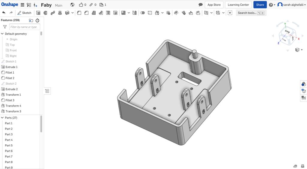
Robot chassis
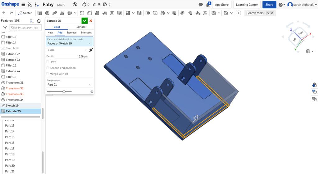
By using Onshape, I created the robot chassis. I started by selecting a rectangle command from the toolbar. I changed the dimention to 12*9 cm.
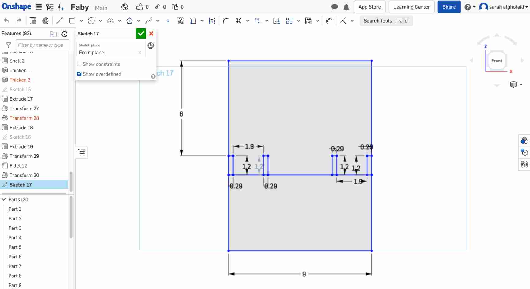
Then, I determined the Dc geared motor place with suitable dimensions for its size. Also, I included holders in each side of the motors.
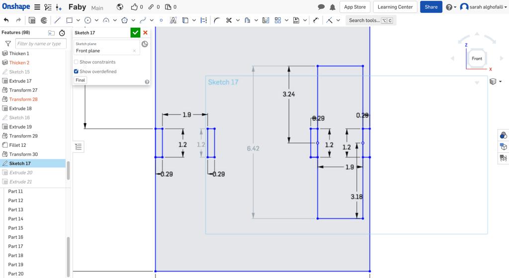
After that, I extruded the chassis to 6 mm depth and the mounting brackets to mm depth.
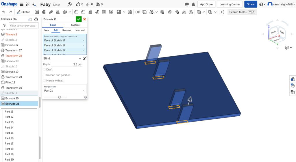
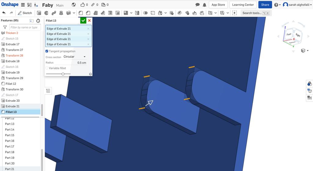
I selected all the sharp edges to round them by clicking on the Fillet function from the toolbar. Then, I specified the cross section to be Circular and typed the Radius measurement 0.5 cm.
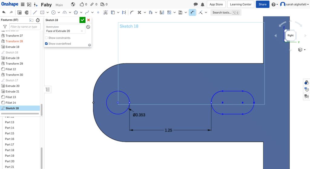
The next step was creating holes for the screws. Each mount bracket has two different holes sizes, the hole in the top with 3.5 mm size and the one in the bottom 6.5 * 3.5 mm.
After that, I extruded the DC geared motor position to 0.4 mm depth.
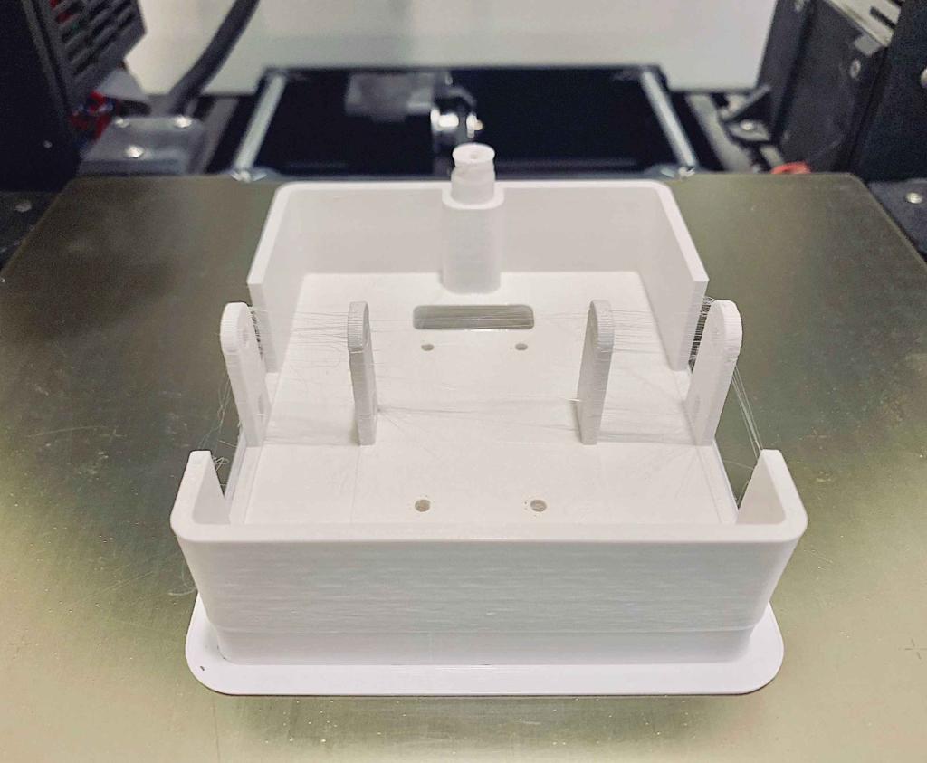
In this step, I decided to print the chassis as a prototype to check if it is suitable for the DC geared motors or not.
I printed the model using a Prusa 3d printer with a white ABS filament. I noticed it is weaker and less rigid than PLA filament.
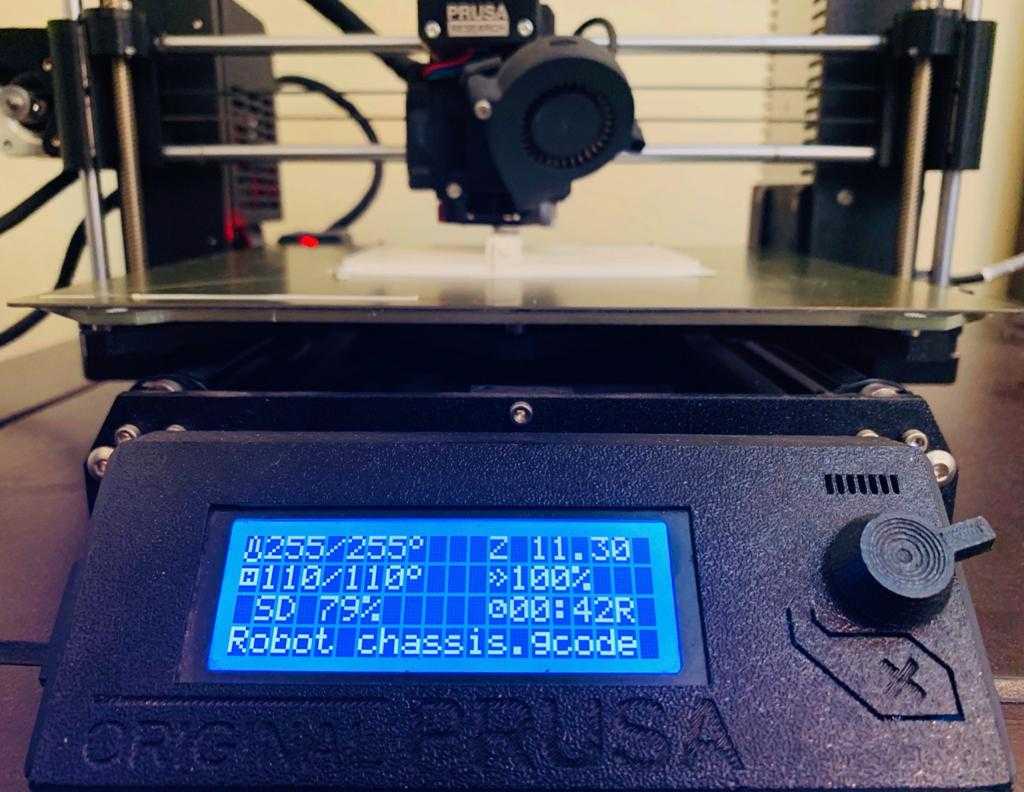
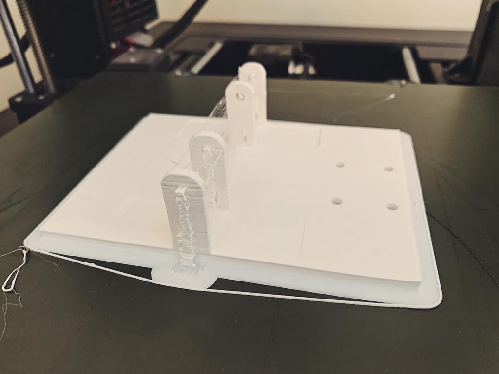
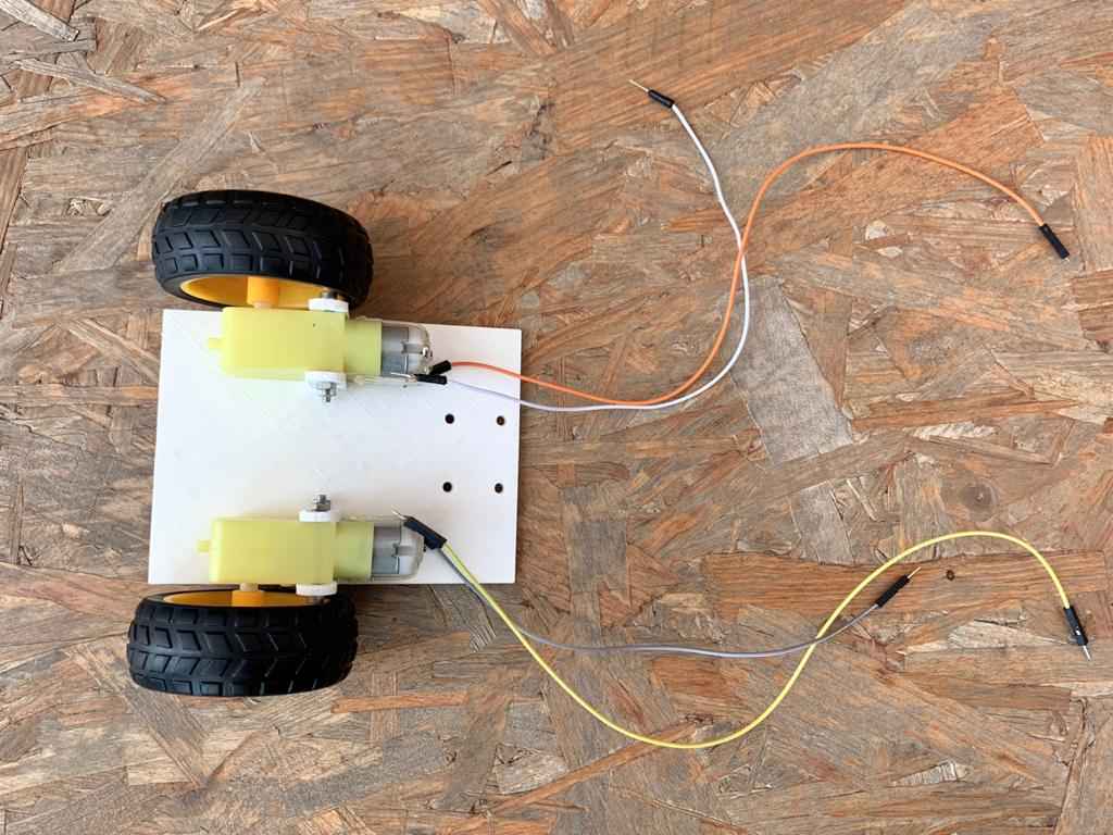
Yay ! the motors fitted exactly in the chassis.
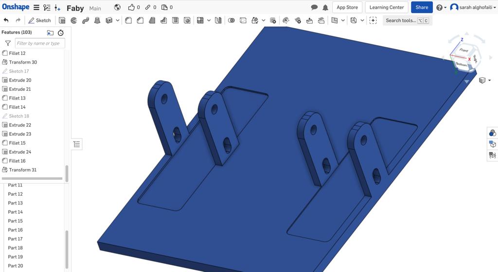
After making sure that all the measurements were perfect, I continued the chassis design by creating a frame around it to hide the motors and the wires.
In the back area of the chassis, I drew a holder for the mini caster wheel and extruded it to 23 mm. The thickness of the frame that I used was mm.
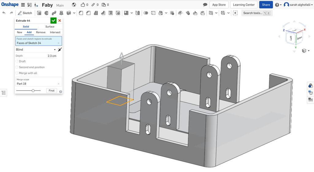
At last, I created holes for the wires and screws that connected the chassis with the robot body.
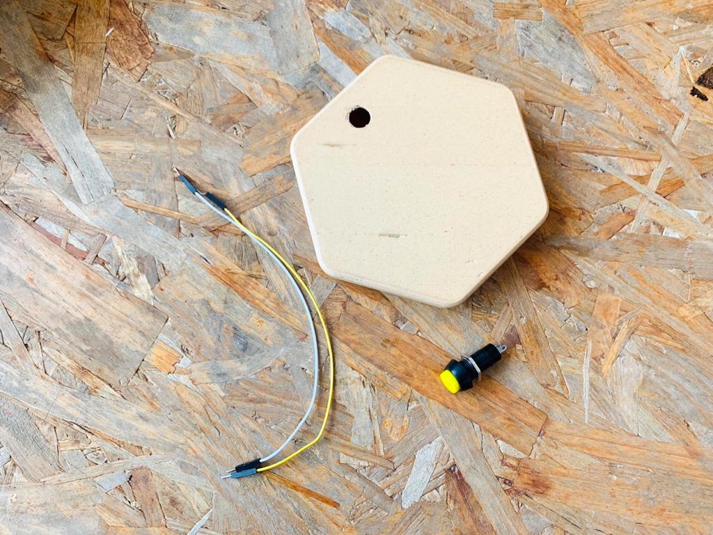
Robot body
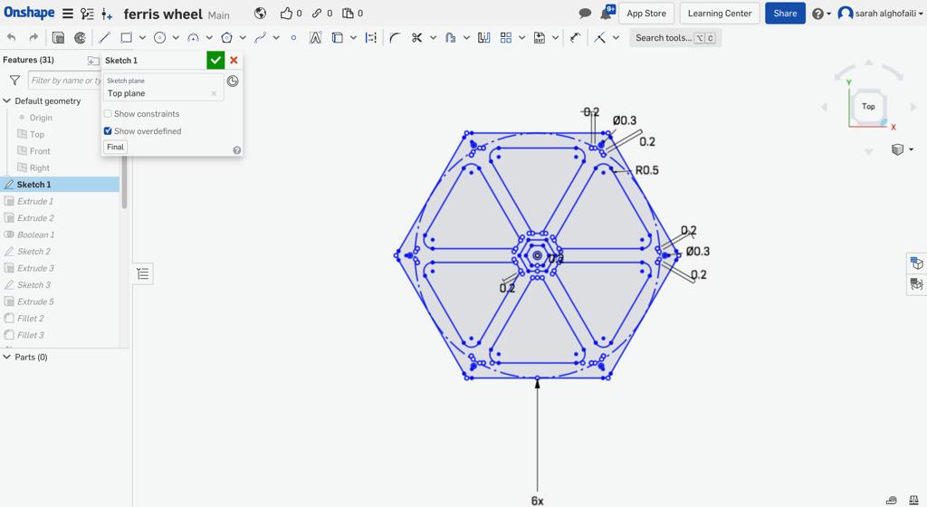
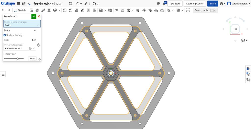
For the Robot body, I decided to design it in a hexagon geometric shape to match the angle brackets symbol shape. I Sketched it by clicking on Inscribed polygon from the toolbar. Then, I dragged the shape to set the circumference.
In Onshape, there are two ways to determine the number of the polygon sides :
Drag towards the polygon to reduce the number of sides.
Drag away from the polygon to increase the number of sides.
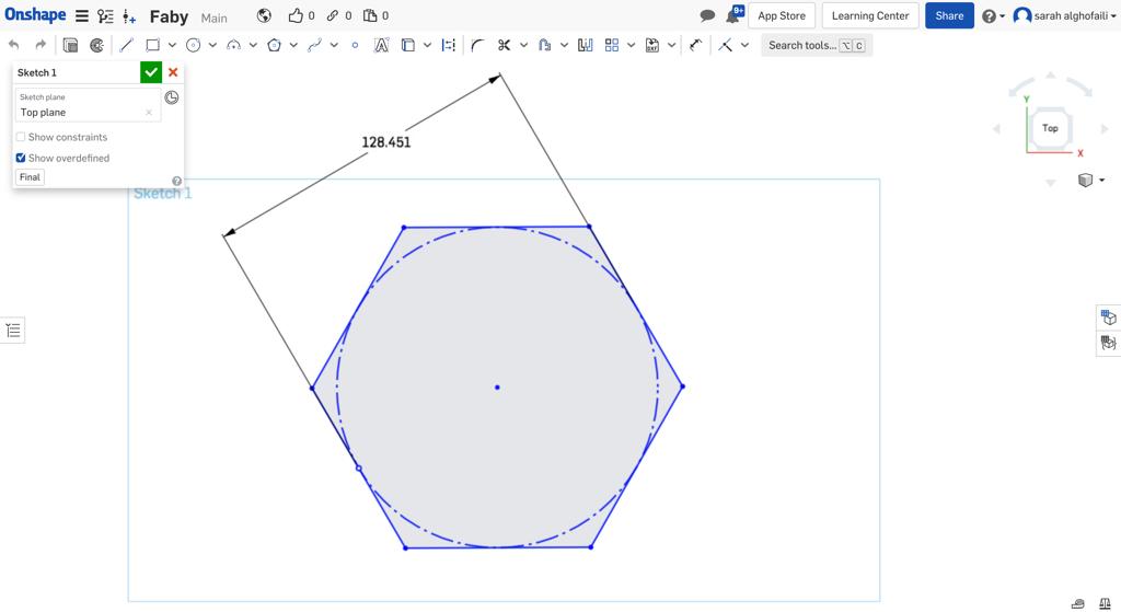
Next, I extruded the sketch with 90 mm depth and filleted all the edges with a radius value = 25 mm.
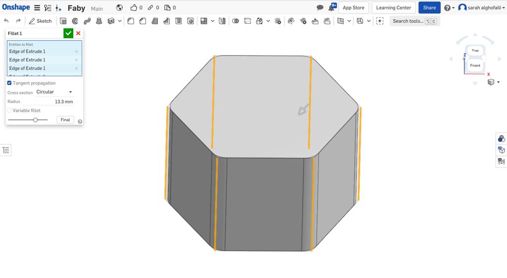
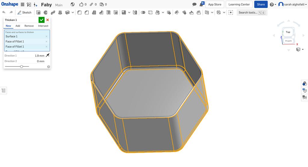
After that, I deleted the top face to leave the part open.
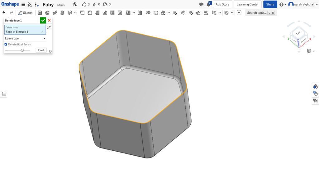
Then, I added a thickness for all faces of surfaces.
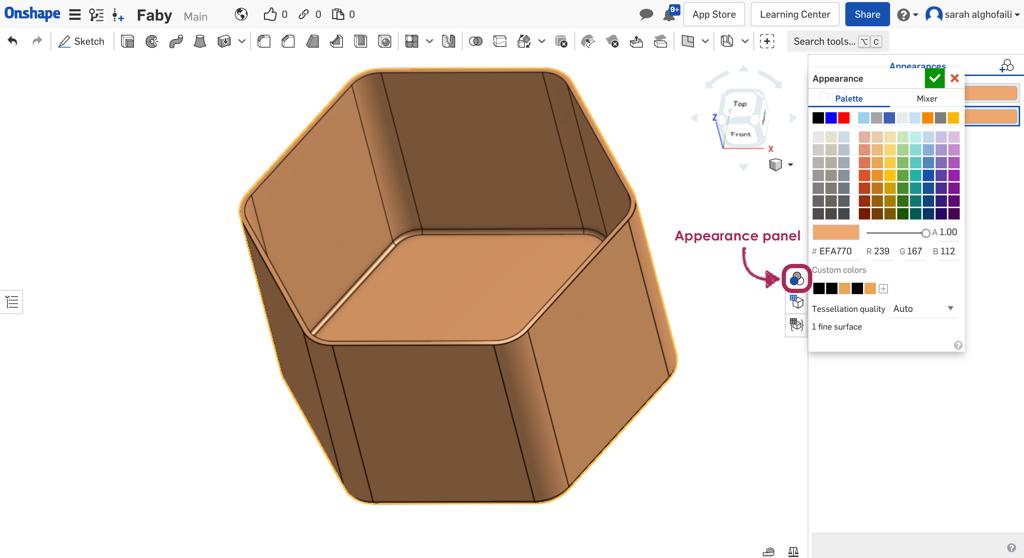
For changing the body color I clicked on the appearance panel and selected the color.
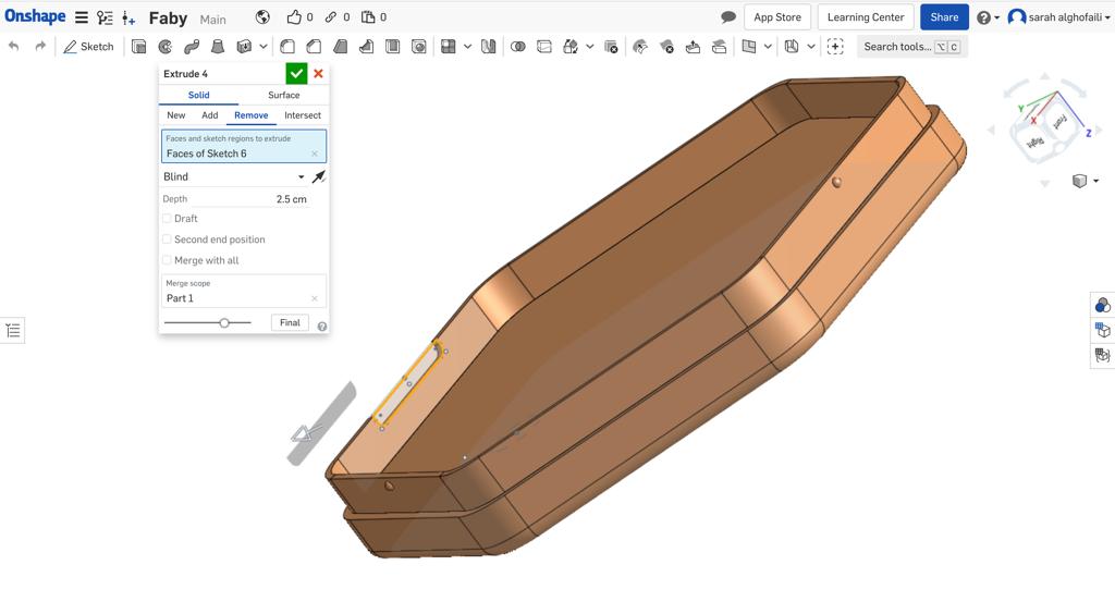
In the bottom of the part, I created 4 holes for the wires and screws in the same place of the chassis’s holes.
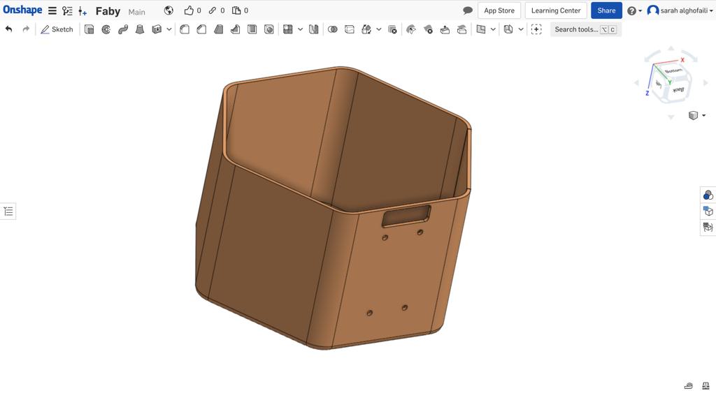
The last step, I created a cover for the robot body.
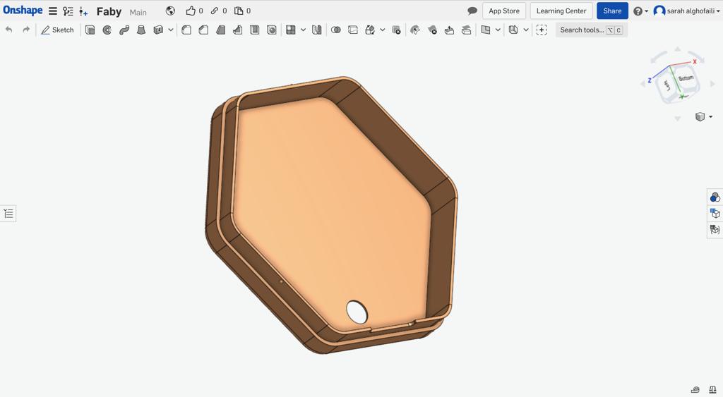
Mini caster wheel
One of the parts required to build the robot is the mini caster wheel. At that time, I could not buy the caster wheel because there was a 24-hour curfew and lockdown due covid-19. For this reason ,I decided to design and 3d print this part.
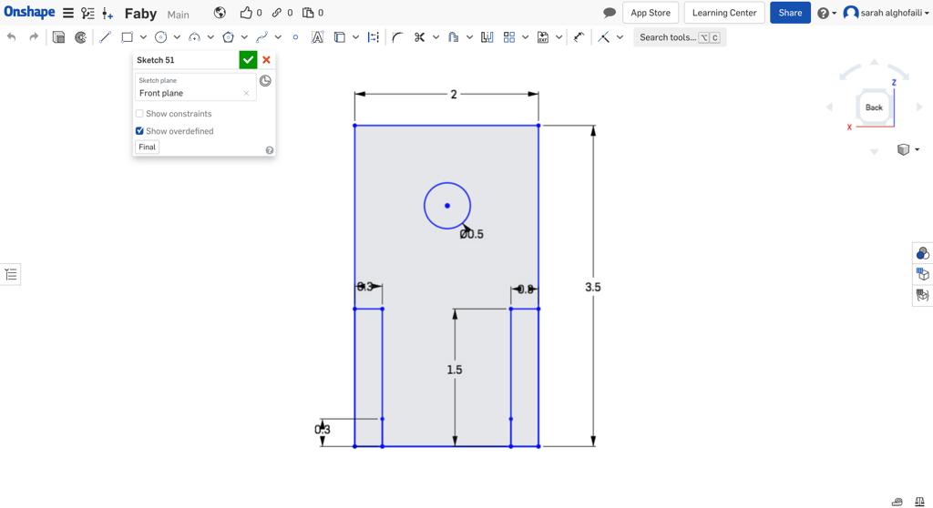
I started by designing the wheel holder. First, I sketched a rectangle with one hole and two mounting brackets.
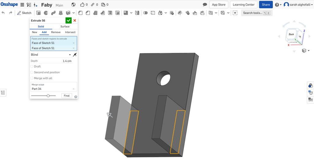
After that, I extruded the holder by clicking on the Extrude tool.
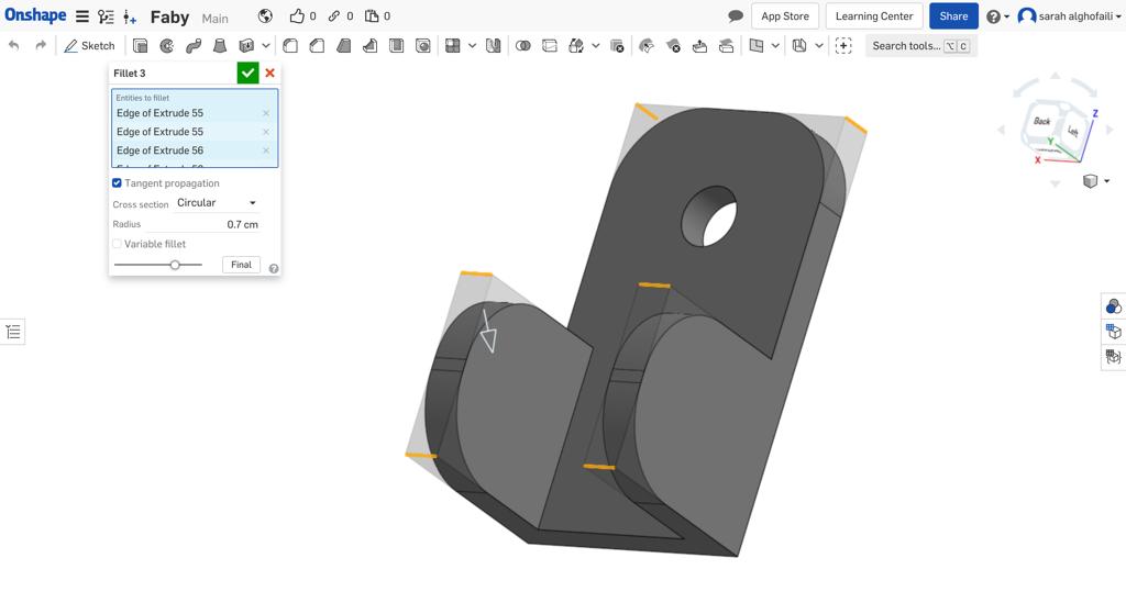
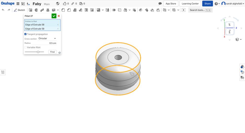
Then, I used the Fillet tool for the edges.
For the wheel, I drew a circle with a hole in the middle and extruded it.
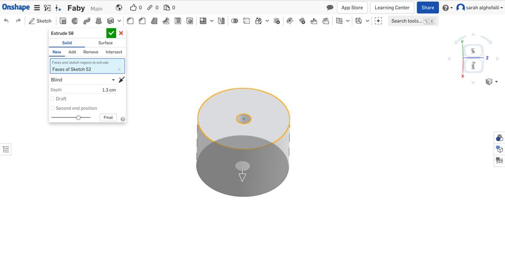
Also, I have used the Fillet tool to make the wheel smother.
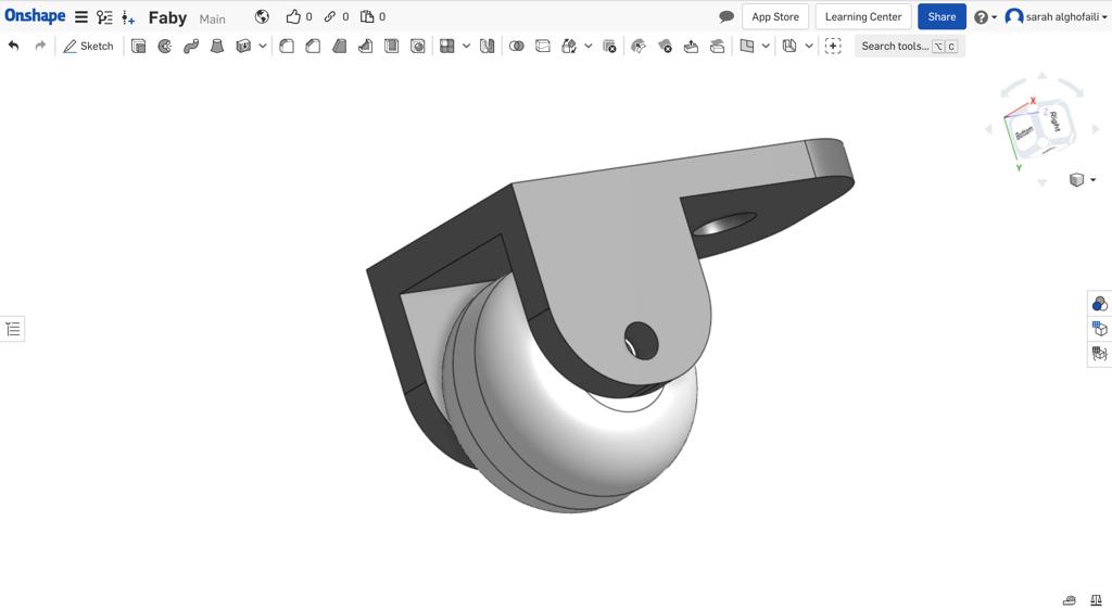
In the assembly page, I connected all parts to show the final look.

Additive Fabrication
I started the fabrication process using 3d printing to bring designs to life. I started to print the robot chassis with the ABS white filament.
Then, I chose the woodfill filament for the robot body. It printed perfectly ! Also, I printed the cover with the same matirial.
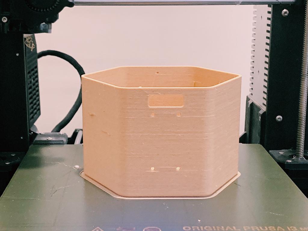
For the rest parts, I used the PLA filament with different colors.
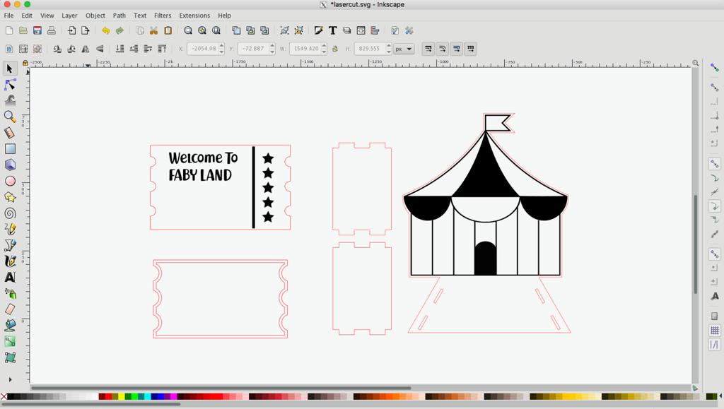
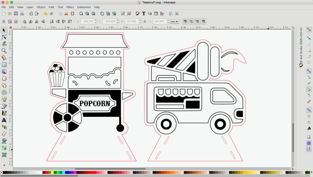
2D design
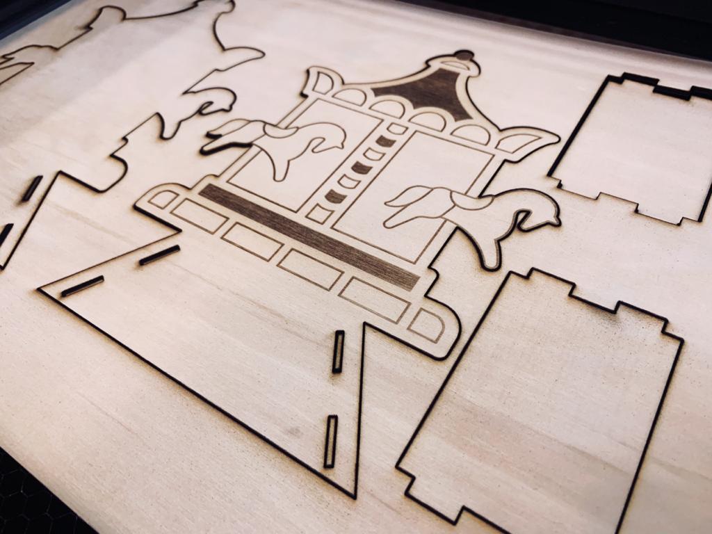
I decided to make a 2D design for the blocks. As I mentioned before, the blocks will look like the amusement park, such as a circus tent, carousel, ferris wheel, etc.
Subtractive Fabrication
The plywood is the material that I decided to use for the blocks. To make sure it is suitable for my project I made a small experiment to test if the plywood thickness will dielectric the RFID reader to read the tags or not. The thickness of the plywood is 2 mm and the thickness of the 3D model 2mm.
For fabricating the blocks, I used the Full Spectrum laser cutter.
Designing my Fabyduino !
PCB Design
The microcontroller that I decided to use is Atmega 328p from Atmel.
What is ATMEGA328P microcontroller?
Atmega 328p from Atmel is a high performance, low power controller from Microchip. It is an 8-bit microcontroller based on AVR RISC architecture. It is the most popular of all AVR controllers as it is used in ARDUINO boards.
Atmega 328p features :
High Performance, Low Power AVR® 8-Bit Microcontroller.
Microcontroller that is pre-loaded with the Arduino UNO 16MHz bootloader.
Advanced RISC Architecture.
Digtal 14 Pin I\O.
Analog 6 Pin input.
131 Powerful Instructions – Most Single Clock Cycle Execution.
32 x 8 General Purpose Working Registers.
Fully Static Operation.
Up to 20 MIPS Throughput at 20 MHz.
On-chip 2-cycle Multiplier.
Atmega 328p pins :
Pinout diagram is shown in below
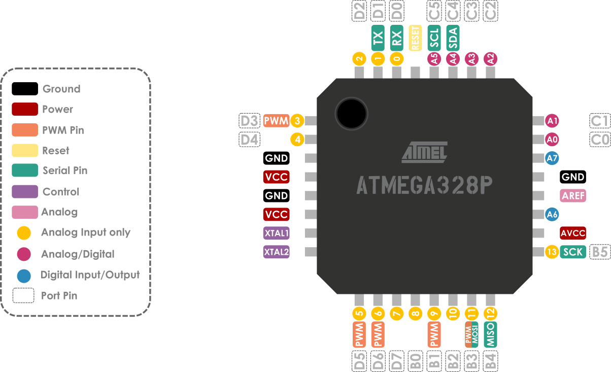
I had to read the Datasheet to identify the pins that I need to use for my project.
Making FABY Board
To design the circuit, I used the electronic design automation software Eagle from Autodesk.
By following the same PCB design process in Week 7, I created a new project file and changed the name to “ Faby project “
To create PCB board there are two main steps:
1- Schematic Diagram
2- Board Layout
Schematic Diagram
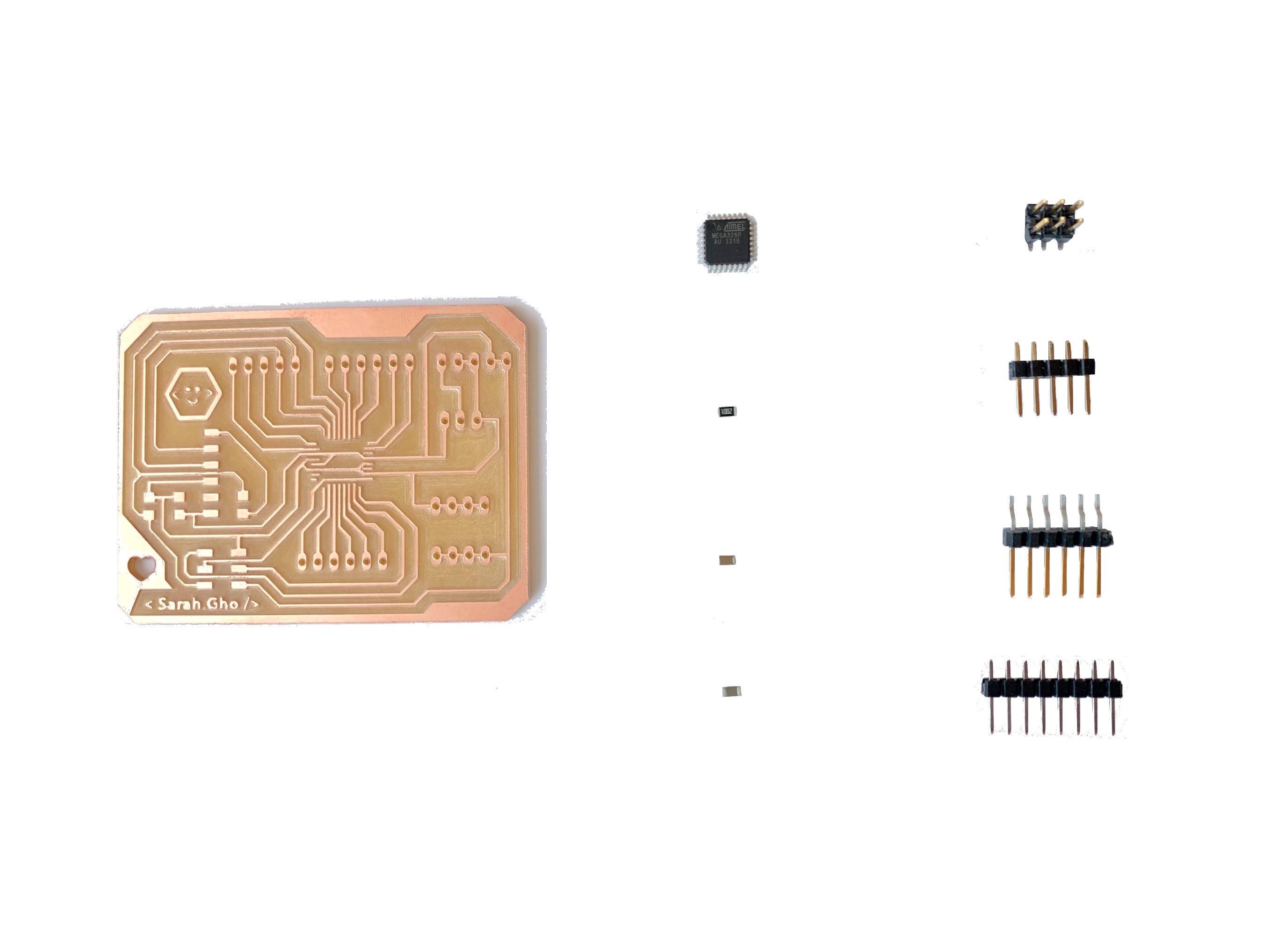
Depending on the microcontroller that I chose, this is the list of the components that I need to import in the schematic.
Atmega328p microcontroller.
100 nF capacitor.
1 uF capacitor.
10 kohm resistor.
Headers (for: inputs/outputs, ISP, VCC, GND, FTDI).
In the schematic editor, I imported the components from the Fab library fab.lbr which I have previously added to the schematic libraries . To add libraries check assignment “ “
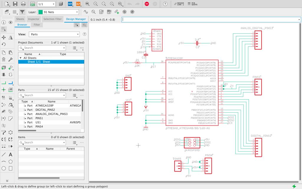
After the schematic is completed, I switched over to the board layout view by pressing the board button.
Board Layout
In the board layout, I clicked the move button to drag the components into the black rectangle to place them.
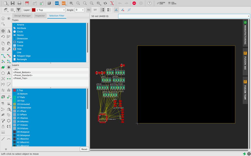
Then, I connected the componnects by following the yellow lines which show the unrouted parts.
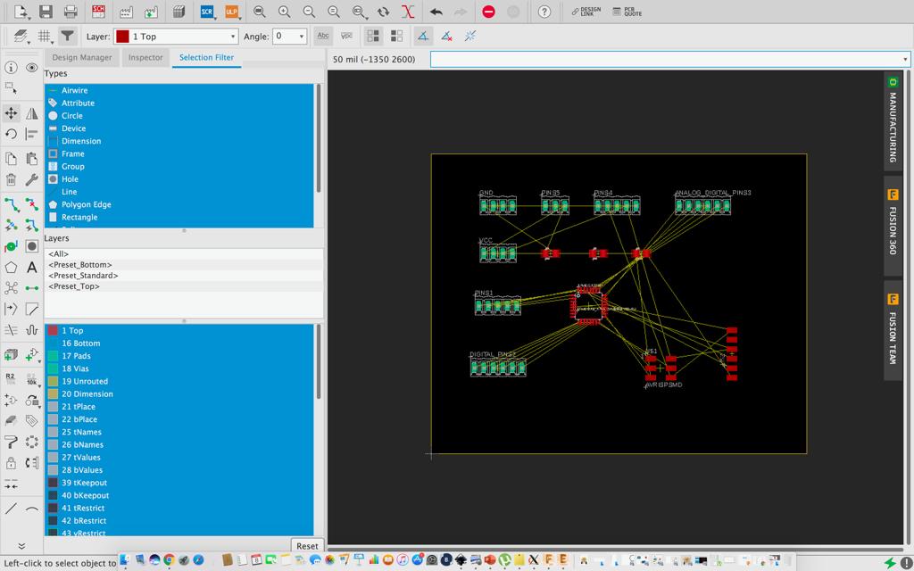
Last but not least, I chose the layers that need to appear in the board layout and I hid the rest.

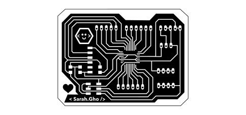
Traces :
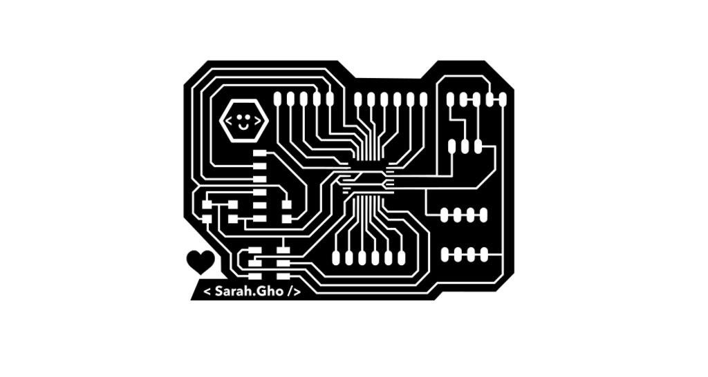
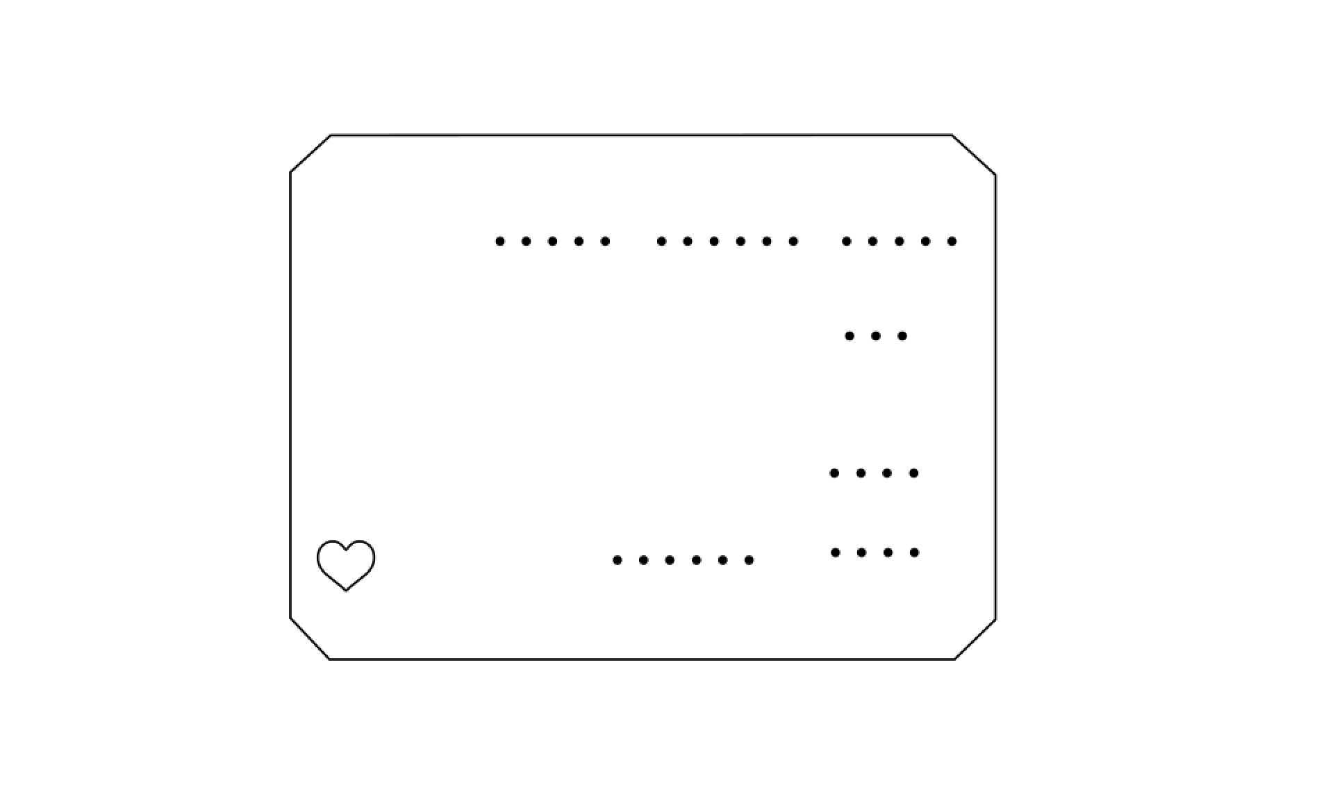
Outline :
Final design :
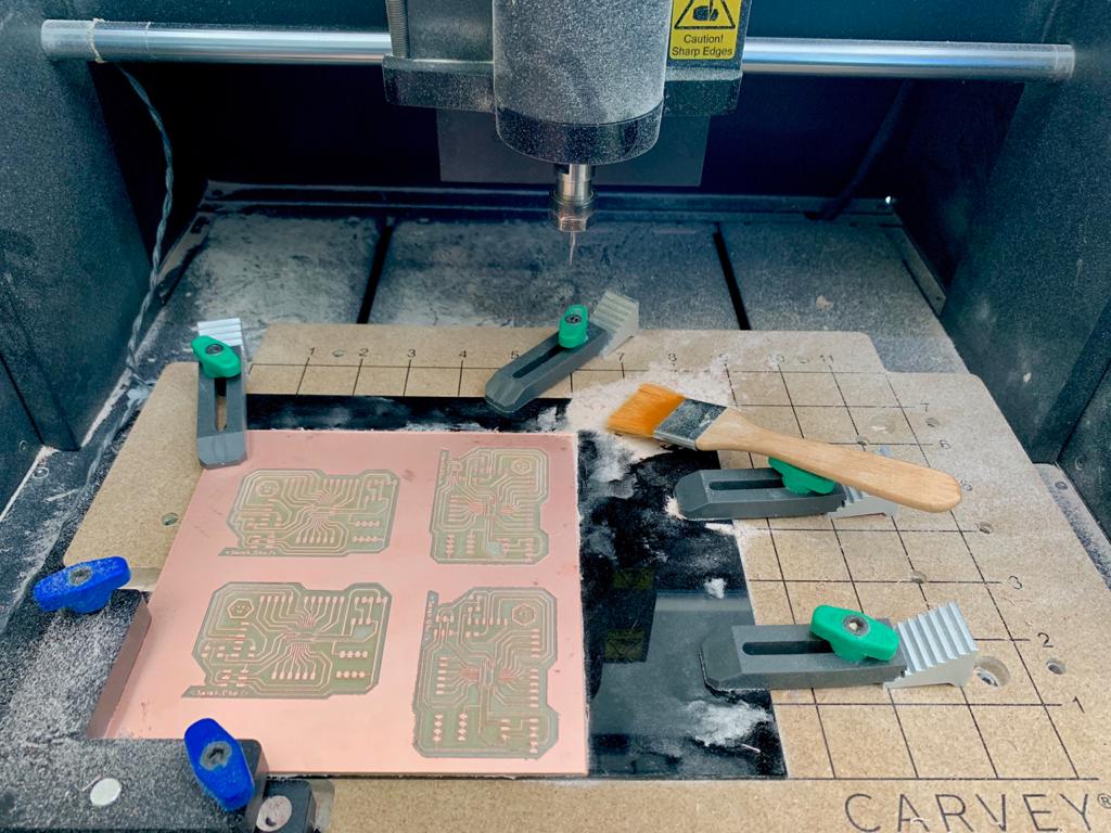
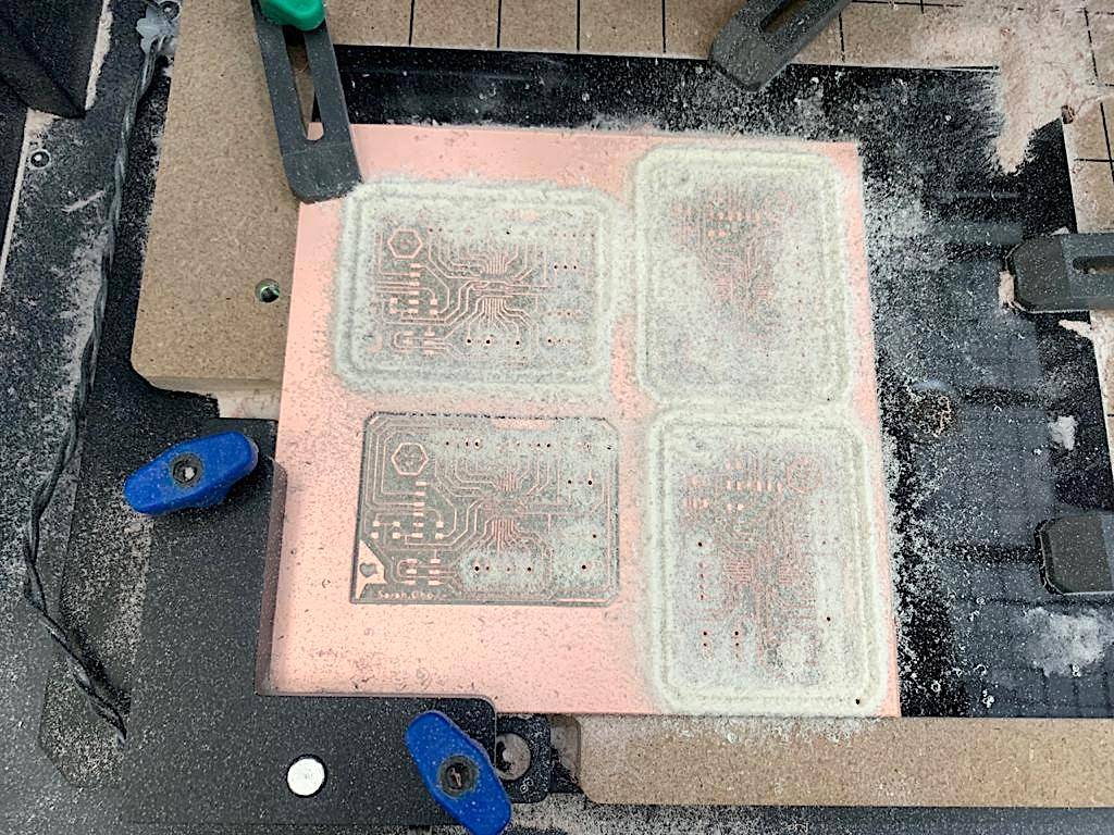
Milling Process
For milling and drilling the PCB, I used the carvy machine. As usual steps, I prepared the carvey machine by placing the copper board on the workspace. Then I chose the proper bit for the milling (Bit : 1/64 in = 0.015 in). For the Depth : 0.2 and the Depth per pass : 0.1 mm.
I put the microcontroller on the PCB board to make sure it fit perfectly.
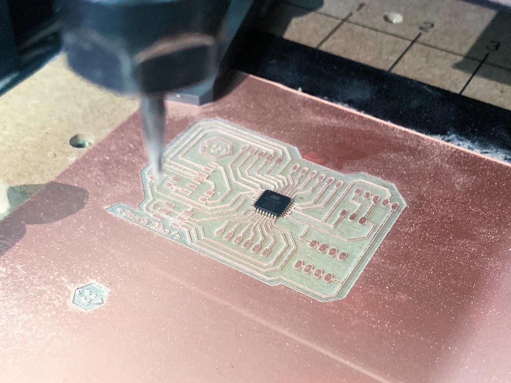
drilling the dots I used Bit : 0.016 in, Depth = 1.8 mm and Depth per pass = 0.3 mm. Also, I used Bit : 1/32 in = 0.031, Depth : 1.8 mm and in Depth per pass : 0.3 mm for the outline.
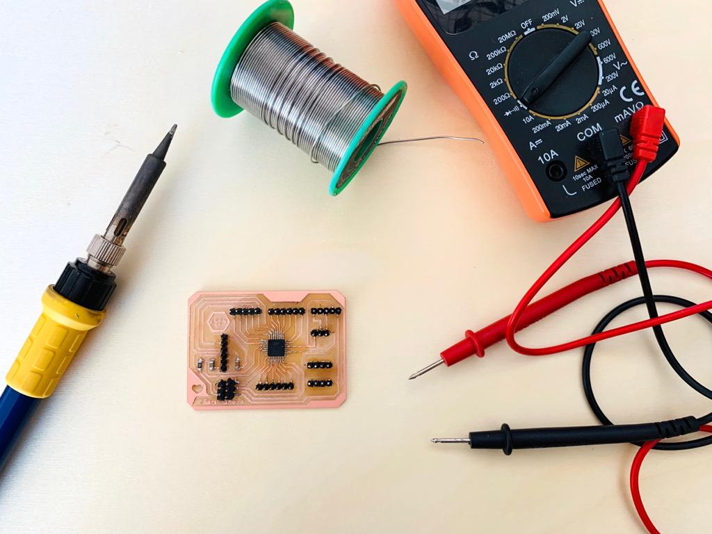
Soldering Process
To start the soldering, I identified all the components that I mentioned before for my Fabyduino.
Electronics
Input
MFRC522 RFID
Switch button
OUTPUT
Geared motors
Buzzer
Motor Driver :
L298 Dual H-Bridge Module
RFID-RC522 Sensor
What is RFID Reader?
RFID means radio-frequency identification, a technology used for electronic and wireless identification of objects, humans and animals. It uses electromagnetic fields to transfer data over short distances.
Specifications:
Input voltage: 3.3V
Frequency: 13.56MHz
Communication : SPI, I2C protocol, UART
Maximum Data Rate: 10Mbps
Read Range: 5cm
How does it work ?
Two-way radio transmitter- receiver, the reader, that sends a signal to the tag and reads its response.
RFID pinout
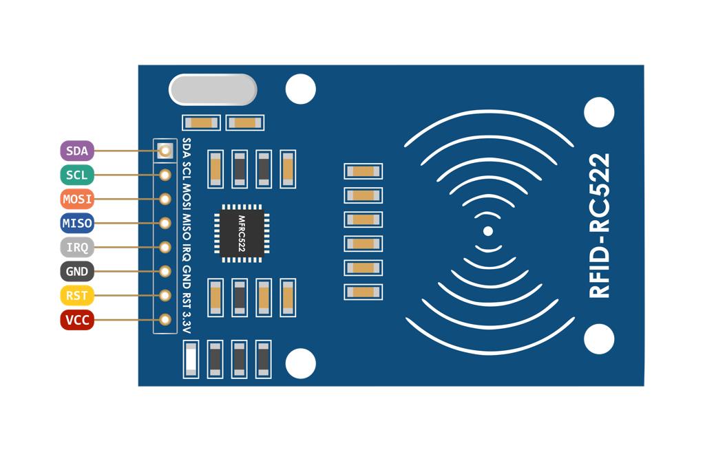
VCC supplies power for the module.
RST is an input for Reset and power-down.
GND is the Ground Pin.
IRQ is an interrupt pin that can alert the microcontroller when RFID tag comes into its vicinity.
MISO / SCL / Tx pin acts as Master-In-Slave-Out when SPI interface is enabled.
MOSI (Master Out Slave In) is SPI input to the RC522 module.
SCK (Serial Clock) accepts clock pulses provided by the Arduino.
SS / SDA / Rx pin acts as Signal input when SPI interface is enabled.
Interfacing of RFID RC522 with Arduino UNO
Each RFID card has a unique ID to present a specific command. I used a simple code to prepare RFID Cards and test it.
Components
Arduino UNO
MFRC522 RFID Reader
RFID Tags
Bread Board
LEDs
To interface RC522 RFID Reader with Arduino UNO I started by adding the library for MFRC522.
The Code:
What is L298 Dual H-Bridge Module Motor Driver?
It is a motor controller breakout board which is typically used for controlling speed and direction of motors.
Specifications:
Driver Model: L298N 2A
Driver Chip: Double H Bridge L298N
Motor Supply Voltage (Maximum): 46V
Motor Supply Current (Maximum): 2A
Logic Voltage: 5V
Driver Voltage: 5-35V
Driver Current:2A
Logical Current:0-36mA
Maximum Power (W): 25W
Current Sense for each motor
Heatsink for better performance
Power-On LED indicator
How does it work ?
The L298N motor driver controls the speed of rotation of a dc motor using PWM (Pulse Width Modulation) signals and the direction of rotation is determined by an H-bridge.
Heatsink for better performance
Power-On LED indicator
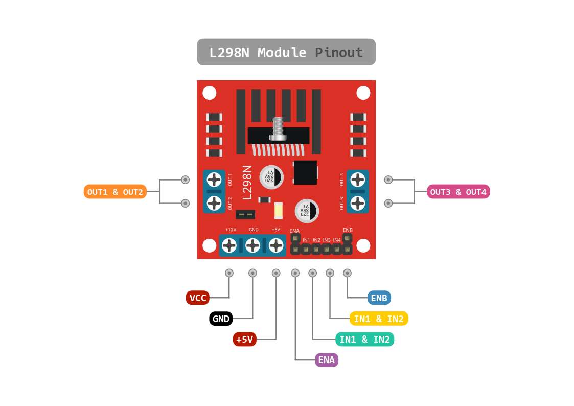
Pin descriptions :
IN1 & IN2: Motor A input pins that used to control the spinning direction of Motor A.
IN3 & IN4: Motor B input pins that used to control the spinning direction of Motor B.
ENA: Enables PWM signal for Motor A.
EN: Enables PWM signal for Motor B.
OUT1 & OUT2: Output pins of Motor A.
OUT3 & OUT4: Output pins of Motor B.
12V: 12V input from DC power Source.
5V: Supplies power for the switching logic circuitry inside L298N IC.
GND: Ground pin.
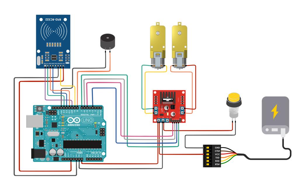
Wiring
Start by connecting the power supply to the motors.
Connect the input and enable pins (IN1, IN2, IN3 andIN4) of the L298N module are connected to Arduino digital output pins(5, 6, 3, and 7).
Connect one motor to terminal A(OUT1 & OUT2) and the other motor to terminal B(OUT3 & OUT4).
For the RFID, I connected pins (SDA, SCL,MOSI,MISO,GND,RST and 3.3V) to (10,13,11,12,GND,9,3.3V).
Then I connected the buzzer to pin 8 and GND.
Programming
The Code explanation:
I started by adding the SPI bus library
#include "SPI.h"
Then I added the RFID reader library
#include "MFRC522.h"
Also, I added the pitches.h which is the library that contains all the pitch values for typical notes.
#include "pitches.h"
Next, I define some pins :
- slave select pin
#define SS_PIN 10
- Define reset pin
#define RST_PIN 9
The next step was creating variable integers :
int M2S=3;
int M2D=7;
int M1S = 5;
int M1D = 6;
int x=0;
int y=0;
int z=0;
int n=0;
int f=0;
After that, I Instantiated a MFRC522 reader object.
MFRC522 rfid(SS_PIN, RST_PIN);
After that, I Instantiated a MFRC522 reader object.
MFRC522 rfid(SS_PIN, RST_PIN);
I created a MIFARE_Key struct named 'key', which will hold the card information.
MFRC522::MIFARE_Key key;
In the Setup function, I initialized the serial communications with the PC, SPI library and MFRC522 object.
void setup() {
Serial.begin(9600);
SPI.begin();
rfid.PCD_Init();
I Set all the motor control pins and buzzer to outputs.
pinMode(M1S, OUTPUT);
pinMode(M1D, OUTPUT);
pinMode(M2S, OUTPUT);
pinMode(M2D, OUTPUT);
pinMode(8,OUTPUT);
In loop function : Look for new cards and Select one of the cards
void loop() {
if(!rfid.PICC_IsNewCardPresent()||!rfid.PICC_ReadCardSerial())
return;
MFRC522::PICC_Type piccType = rfid.PICC_GetType(rfid.uid.sak);
To check is the PICC of Classic MIFARE type:
if (piccType != MFRC522::PICC_TYPE_MIFARE_MINI &&
piccType != MFRC522::PICC_TYPE_MIFARE_1K &&
piccType != MFRC522::PICC_TYPE_MIFARE_4K) {
Serial.println(F("Your tag is not of type MIFARE Classic."));
return;
The code formats UUID as a string of 4 hex bytes (each bytes a pair of hex digits) separated by colons.
Blank the string
String strID = "";
Iterate over the four bytes of the UUID
for (byte i = 0; i < 4; i++) {
Next, I added the following to the string "ID"
strID +=
If the hex number to be displayed is less than 0x10, add a leading '0' to the string 'ID'
(rfid.uid.uidByte[i] < 0x10 ? "0" : "") +
Then, I added the UUID to the string 'ID' as HEX.
String(rfid.uid.uidByte[i], HEX) +
Adds a colon to the string 'ID' after the hex byte unless the index is 3 (ie the last one).
(i!=3 ? ":" : "");
strID.toUpperCase();
Serial.print("Tap card key: ");
Serial.println(strID);
I turned off motors - Initial state
if (strID.indexOf("29:2D:A1:B2") >= 0 && n==0 && y==0 && z==0)
digitalWrite(M1D,LOW);
analogWrite(M1S,0);
digitalWrite(M2D,LOW);
analogWrite(M2S,0);
delay(800);
I turned on motor - Moving forward
digitalWrite(M1D,LOW);
analogWrite(M1S,255);
digitalWrite(M2D,LOW);
analogWrite(M2S,255);
x=1;
} else if(strID.indexOf("29:2D:A1:B2") >= 0 && n==1) {
If it is the true card then play this melody
int melody[] = {
NOTE_D7 , NOTE_B6 , NOTE_D7, NOTE_G7
int noteDurations[] = {
4, 8, 4, 4
iterate over the notes of the melody
for (int thisNote = 0; thisNote < 4; thisNote++) {
To calculate the note duration, take one second divided by the note type.
int noteDuration = 1000 / noteDurations[thisNote];
tone(8, melody[thisNote], noteDuration);
int noteDurations[] = {
4, 8, 4, 4
To distinguish the notes, set a minimum time between them. The note's duration + 30% seems to work well:
int pauseBetweenNotes = noteDuration * 1.30;
delay(pauseBetweenNotes);
stop the tone playing:
noTone(4);
y=0;
z=0;
n=0;
f=0;
else if(strID.indexOf("29:2D:A1:B2") >= 0 && n==0 && f==1){
If it is a false card then play this melody
int melody[] = {
NOTE_A2 , NOTE_B1 , NOTE_A2
};
int noteDurations[] = {
4, 4, 4
};
for (int thisNote = 0; thisNote < 3; thisNote++) {
To calculate the note duration, take one second divided by the note type.
int noteDuration = 1000 / noteDurations[thisNote];
tone(8, melody[thisNote], noteDuration);
To distinguish the notes, set a minimum time between them.
int pauseBetweenNotes = noteDuration * 1.30;
delay(pauseBetweenNotes);
noTone(3);
The Code:
The pitches:
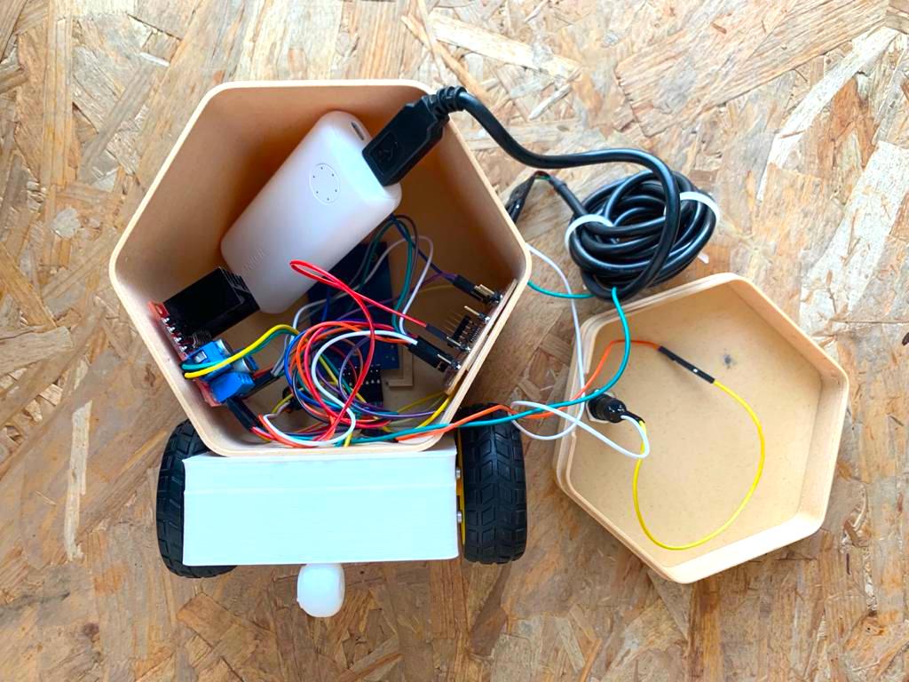
Assembling
Faby robot Assembling
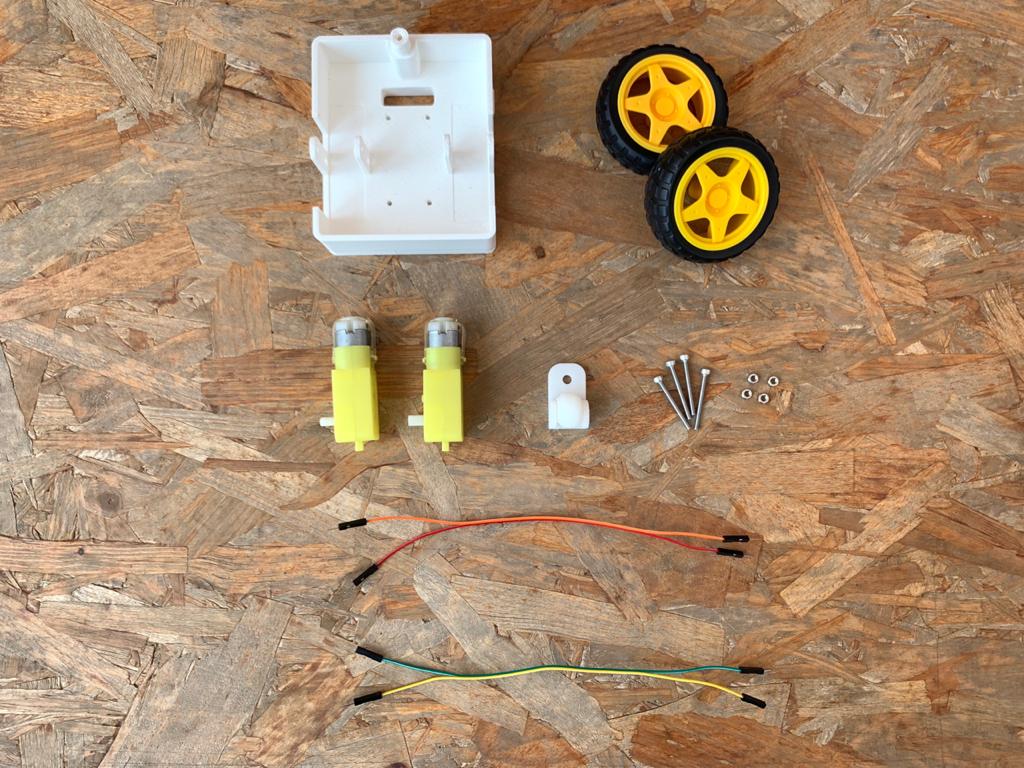
I started by assembling the robot chassis. First, I gathered all the components:
Robot chassis x 1
DC gear motor x 2
L298N motor driver x 1
Wheel x 2
Mini caster wheel x 1
Male jumper wires x 4
Screws and nuts
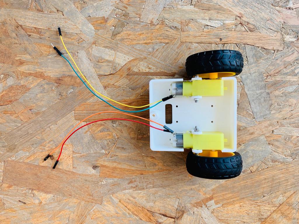
Then, I installed the two motors on the chassis in the mount brackets. After that, I installed the wheel on the chassis with screws and nuts. Also, I tinned the wire with solder and soldered them to the motor terminals. Next, attached the tire wheels to the outside part of the motors and the mini caster wheel in the back area of the chassis.
The next step, I connected the robot body to the chassis. I wired up the PCB, RFID, L298N module , buzzer, switch button and the power bank.
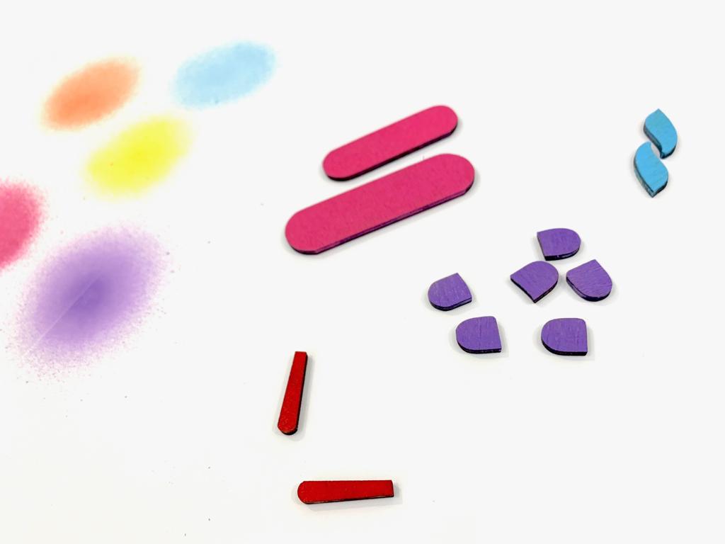
The Blocks Assembling
I colored some parts with spray paint.
Testing Faby
I spent the most time of the project on the programming and testing phases. The testing process helped me to fix all the problems that I faced and showed me the flaws to modify the design.
For instance, controlling the motor speed according to the range and capability of the RFID reader to read the tags.
Last but not least, I uploaded the code to my Fabyduino board to test it.
The Final result : Faby !
