Electronics design

Group assignment
For this week’s group work, we had to use the equipment available in our lab to test the operation of a micro controller. At our lab we have available digital multi-meters and a small digital oscilloscope:
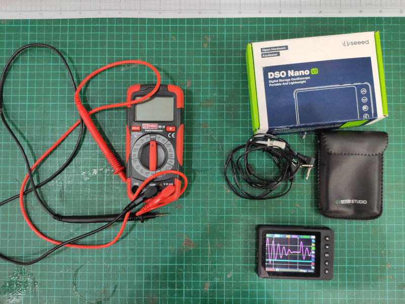 Oscilloscope
We have been using the multimeter already, to test our boards and components, continuity, to double check that we are using the right resistor and the polarity of leds and diodes.
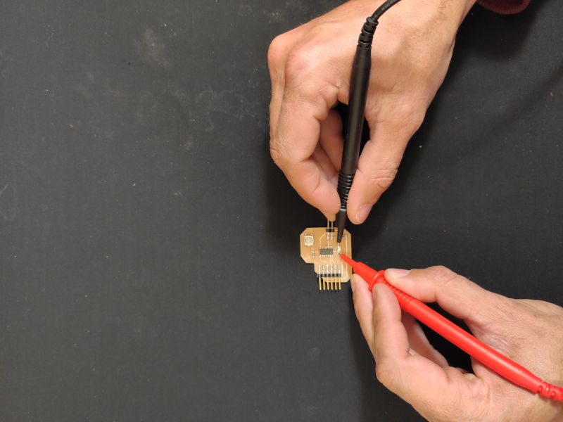
Testing this week's assignment board (I assure you there is a led there and it's on)
I have never used an oscilloscope before, so I had to start what understanding what it is and what it does, this tutorial gave me a quick overview of its functionalities.
Individual assignment
For this week assignment, I have design a board for an Attiny1614 board, including the following components:
- Attiny 1614 micro controller
- 6mm switch.
- Ceramic capacitor 1uF
- Single color green led.
- 499 Ohm resistor.
- 1k Ohm resistor.
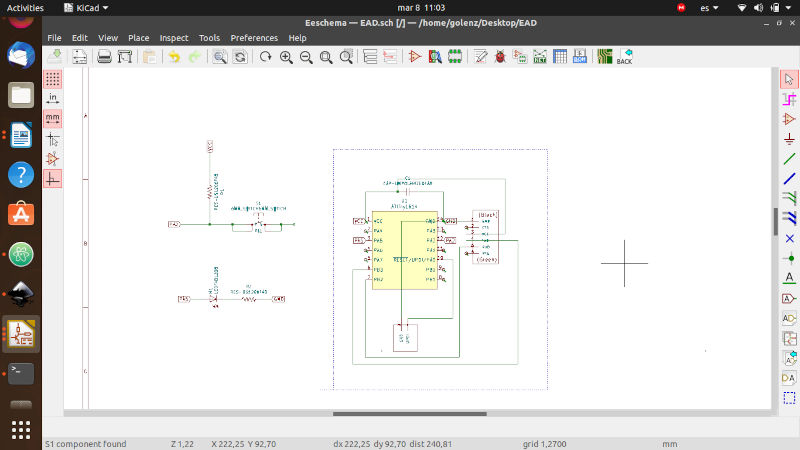
I have used Kicad to design the board schematics, the pcb vector files and to define the design rules.
On the schematics design, we basically create a blueprint of our bouard and all its components. We used the fabacademy library to ensure that all the required components are available
Once we allocate all our components and connections, we create the pcb file, which will lay down all our components in a first draft of how the board will look like:
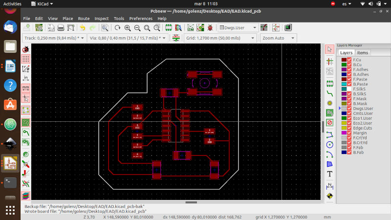
In the picture above, all the traces have been laid down, we have to do this process manually, with the “route tracks” function, to make sure that all traces follow a a correct path and we don’t cause any short in the circuit. Finally we design the shape of our board with the “add graphic lines” function.
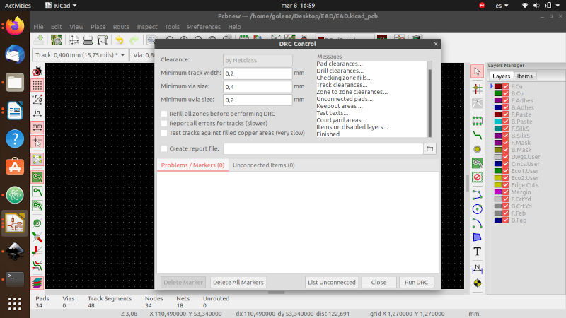
Finally, before exporting our files as svg, we perform a design rules check, to ensure that we don’t have any errors in our design:
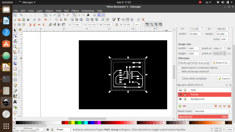
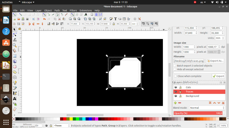
Then we need to create our png files to be able to mill the board, for this we use inkscape. First we need to invert the colors and create separate images for the traces and the board cut so Mods can read them correctly.
We separate the traces and the board into two different layers and invert the colors with the fill in function in inkscape
I used the Roland SRM-20 once again, the trace with was increased, which resulted in a bigger board, but the finish was correct at the first try.
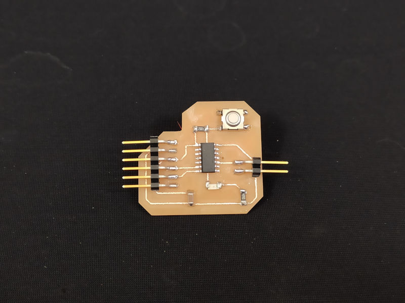
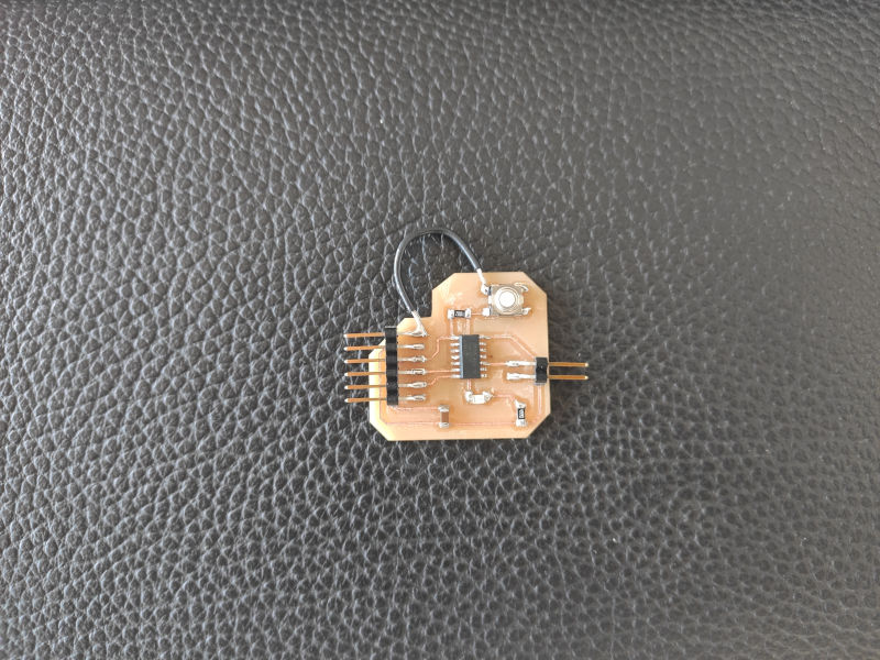
The final result
After some basic tests with the multi-meter, I realized there was something that was not working properly. When having a better look at the traces, I could see that the switch was not connected to the ground, so I had to do the dirty job to fix it:
At first I thought that I removed the trace when cleaning the board with the cutter knife, but checking the Kicad file I can see that the trace what not laid in the first place, which I found curious, because when I checked the design rules, there was no errors or unconnected parts detected.