Link to Embedded Programming Group Page
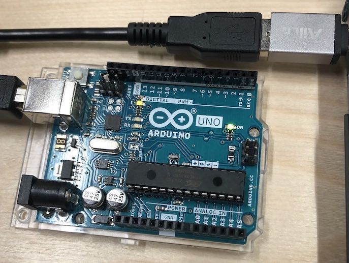
During Week Six: Electronics Design I actually managed to make my board work then to light up an LED and program it in Arduino to flash in different speeds. I had SO MUCH FUN doing this that I would try and take it a step further by learning Arduino more, look into using the parts I will be needing in my project adn seeing if I could get a servo motor to move by pressing a button.
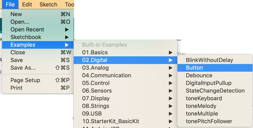
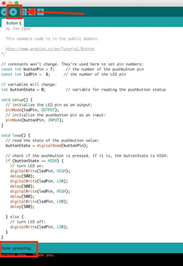
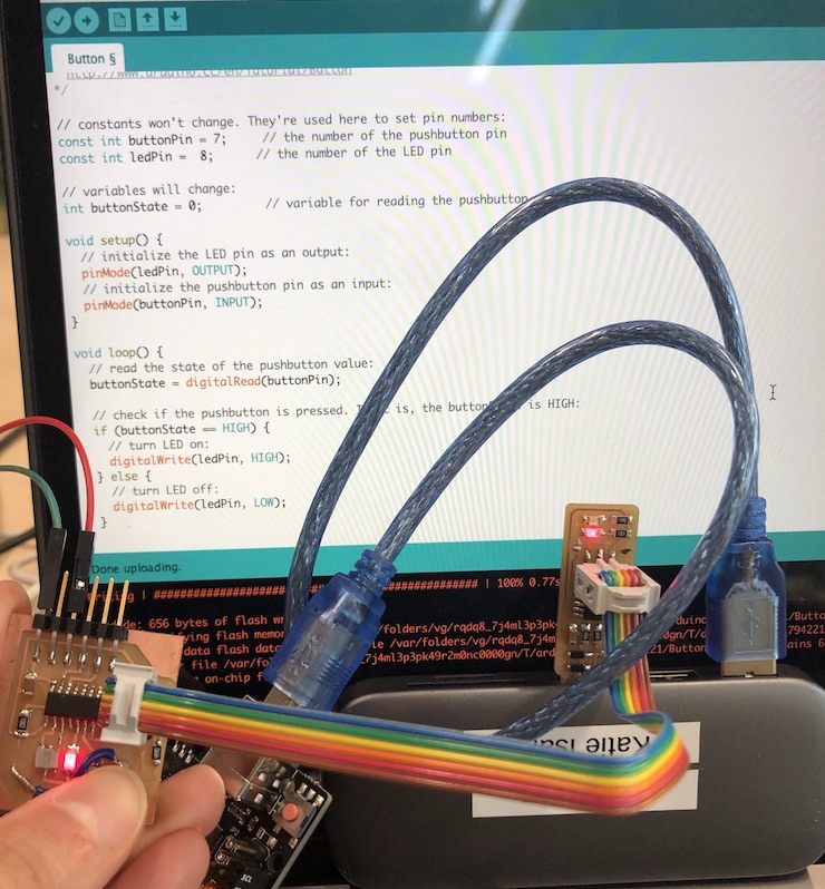
Opening up an example button so that this is easier for me so I don't have to write the code which is great!
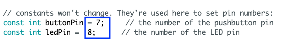
Put the pin that is connected to LED and the Button on the chip in these spaces BUT you need to place the Arduino number not the chip number.
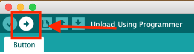
Then upload that to your board...
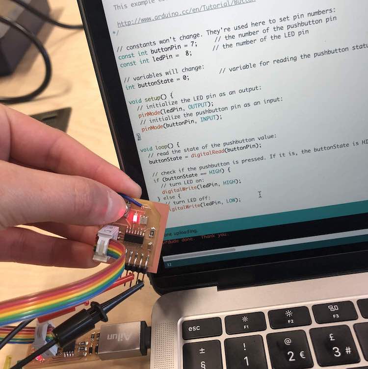
And now you should press your button and it should FLASH! And mine did WOOHOO
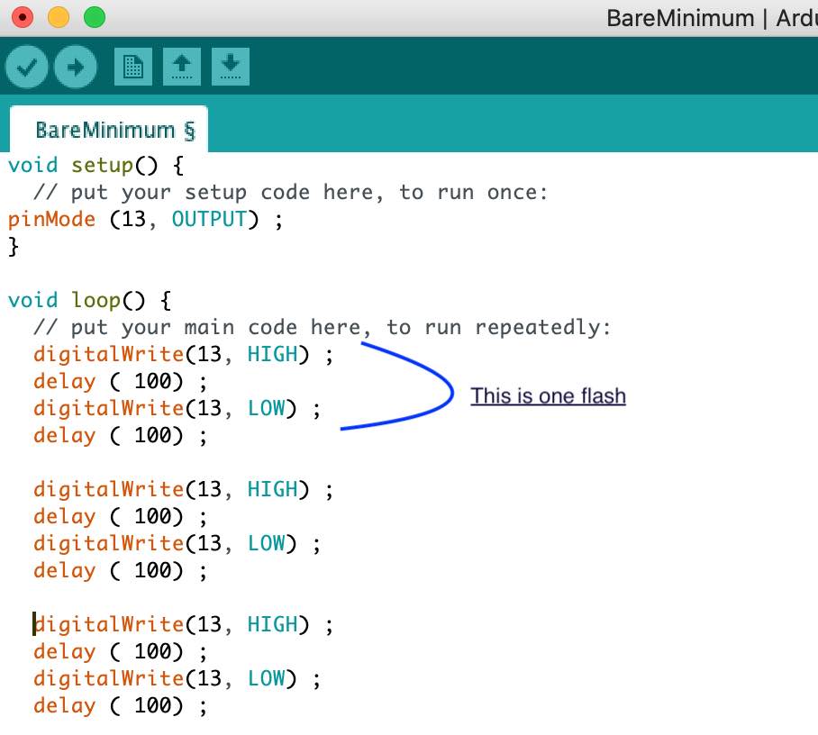
I then had a go and making it flash rather than me having to flash it which was really fun!
Link to Language Reference in Arduino
Arduino Tutorial 1: Setting Up and Programming the Arduino for Absolute Beginners Link to youtube video
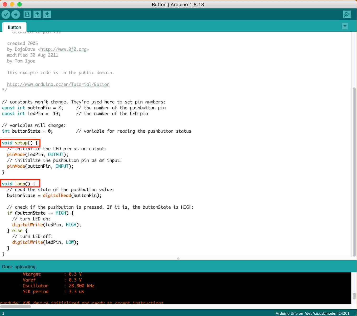
Need to make sure we are talking to the arduino:
Now ready to write first program!
pin 13 = already linked to the LED
What pins are you going to be working with on your Arduino board?
INPUT = retrieving a signal
OUTPUT = gives a signal out
Both of these could be - light, sound, movement etc
Next is to tell the board we are wanting to turn the LED on (HIGH = 5 volts)
You can then press the arrow at the top that comes up as 'upload'
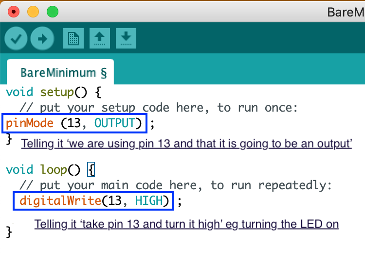
Now to turn it off you need to change 'HIG' to 'LOW'
Arduino Tutorial 4: Understanding Arduino Variables link to youtube video
He got us to make the LED flash like in morse code
SOS
Which is when the light flashes fast 3 times and then slow 3 times and then fast 3 times.
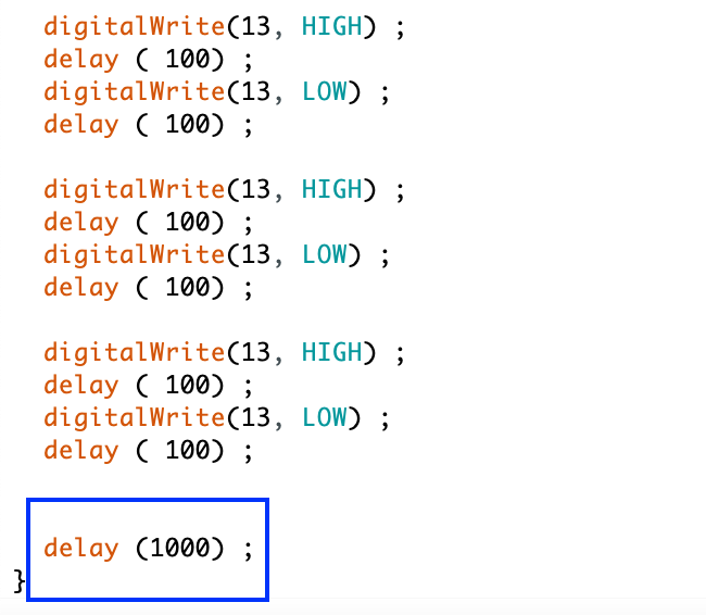
It was going very fast so we added a delay between each SOS
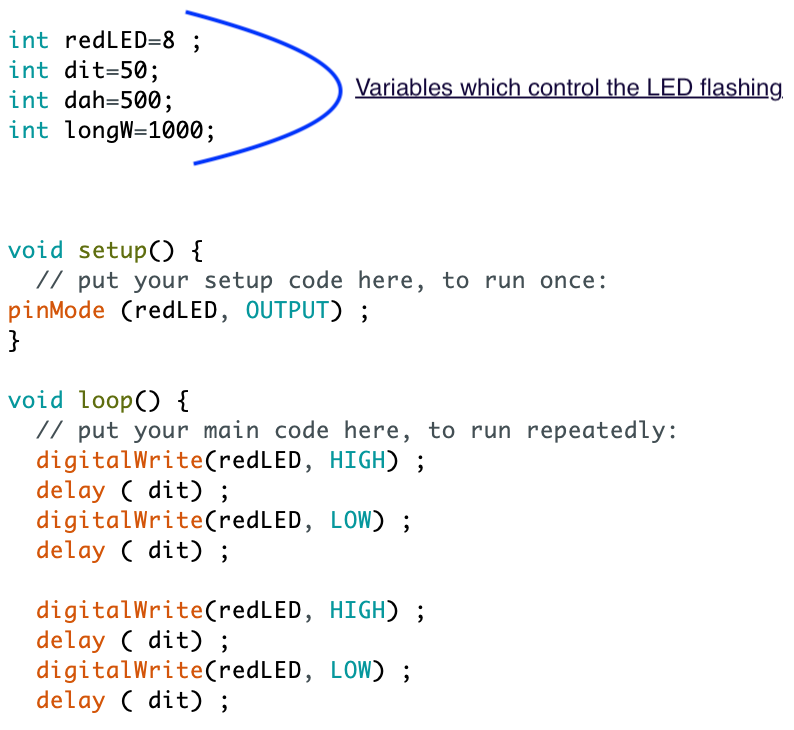
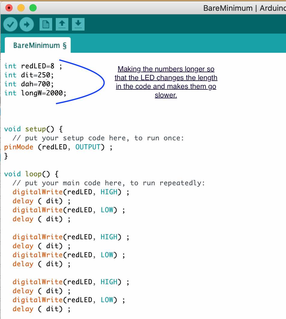
How to change the pin 13 to another pin and also how to change the delay to be quicker - this isn't the best way to do it (hard wiring in the numbers)
We want to set variables - to do this to add them above the 'void set up'
This is where you use int and then name the part you are wanting to use - eg int (this goes blue) reeled
String myName = "Katie Isard" (they need to be in "" quotes
Arduino Tutorial 7: Understanding the Arduino Analog Write Command link to youtube video
Digital = 1 to 13
Analogue = pins with a ~ by the number
Rather than putting HIGH or LOW it is number between 0 and 255
0 = volts
255 = 5 volts
So with analogue anything in between will vary the amount of voltage.
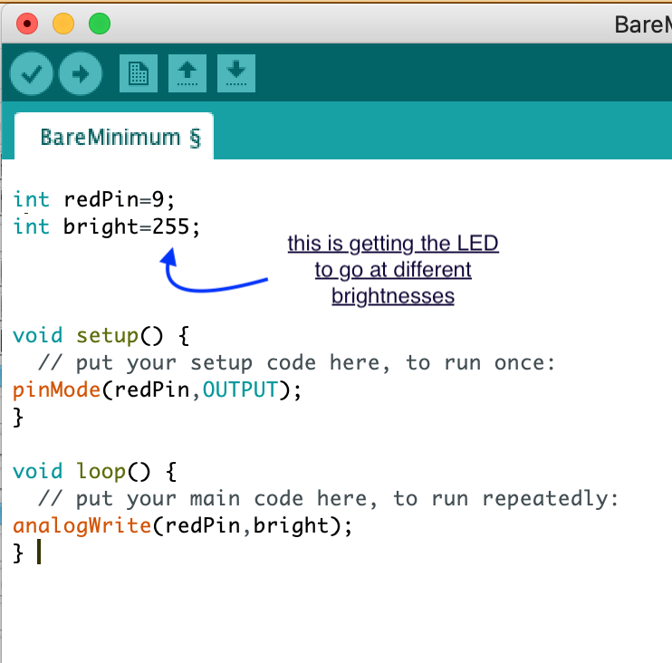
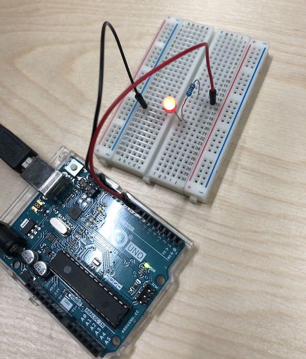
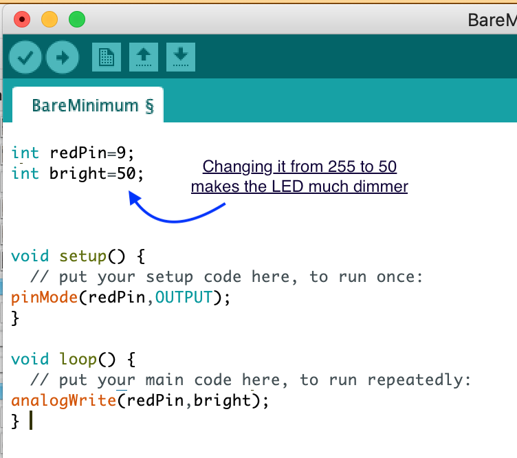
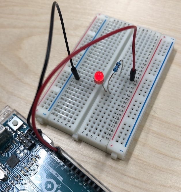
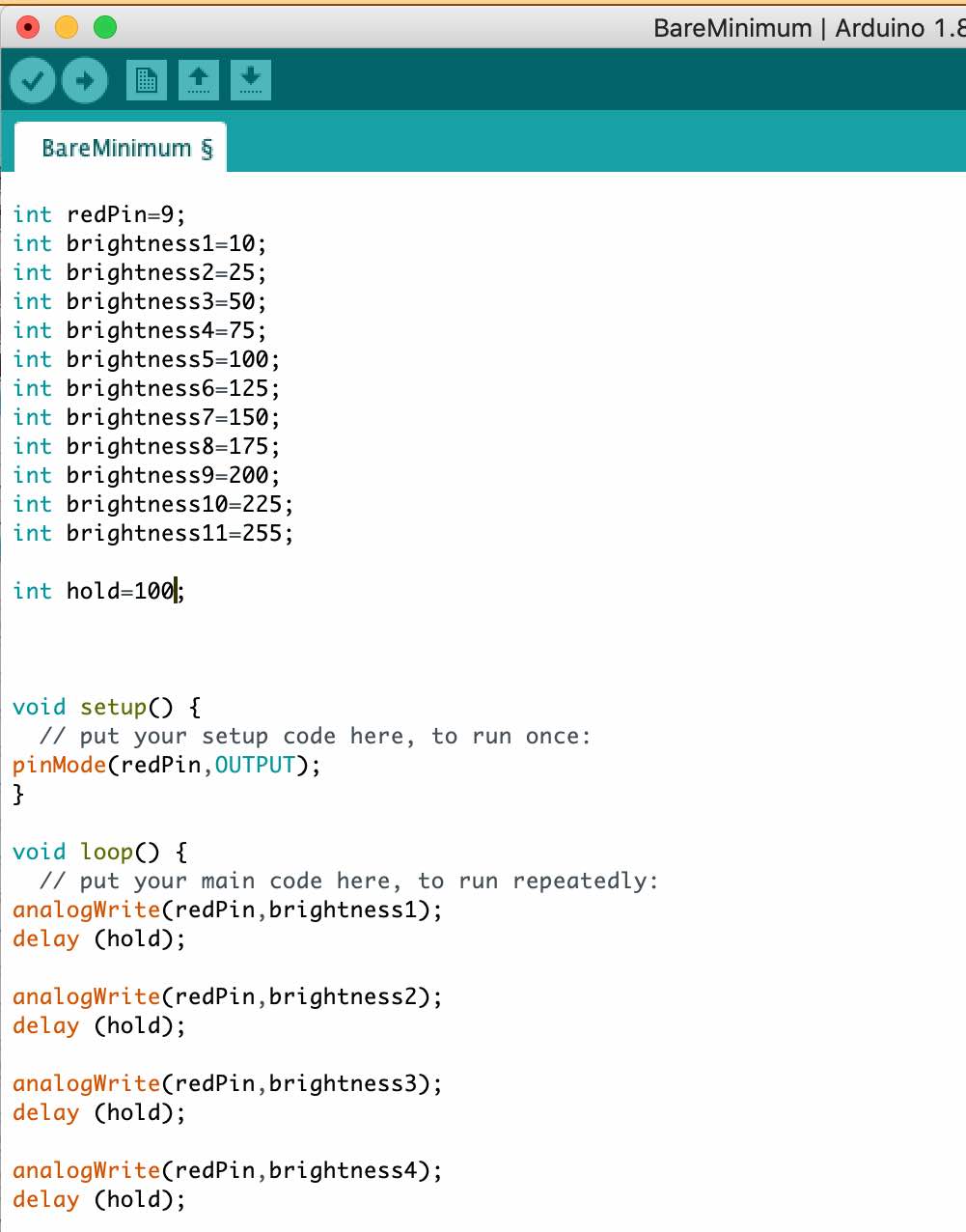
So I then did what was told on the video which was to play around with the LED brightness, so I made it go up and down to go from being bright (255) to almost off (10). This was very fun and worked very well. It almost looked fake when looking at it made me very happy!
Arduino Tutorial 8: Understanding Pulse Width Modulation (PWM) and the Arduino Analog Write Commandlink to youtube video
In this video he is showing what happens when you change the voltage using 225 and 0 with an oscilloscope.
He then showed 127 which is about 2.5 volts and this made the oscilloscope do something interesting where it is trying to fine the average between 5 and 0 volts so makes steps on the screen rather than a line. So it is on 5 volts and then going off for the other part, he also did 10 volts which was tiny and you could barely see the gap between the line at the 0 and then small dots at 5 volts.
This is the same thing for motors - you may want to use a capacitor to help smooth out the signal!
This tutorial really helped me understand voltage and how it all comes together, also about resistors and capacitors.
Followed this tutorial to understand to to get a button to work
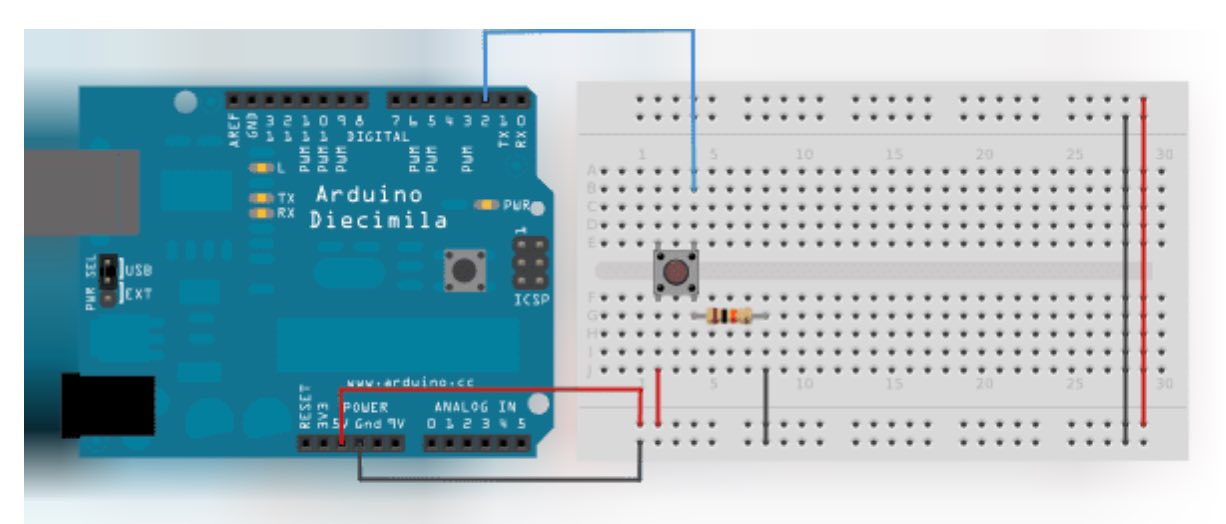
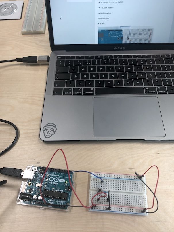
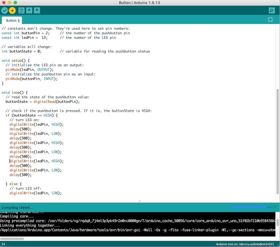
When I then pressed the button the LED lights up and because I then added the 'delay(500);' this then made it flash in a loop as I placed it in the loop section.
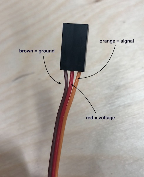
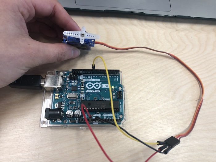
Followed this tutorial to understand to to get a servo to work
A value between 0 and 180 as this is telling it the amount it needs to move
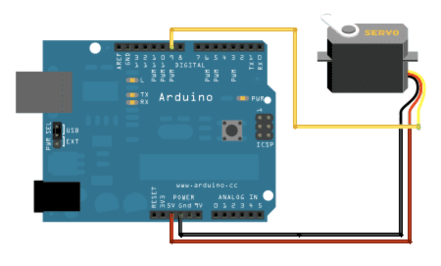
Reading the arduino so that they link up
I then pressed 'Upload' which made the servo move
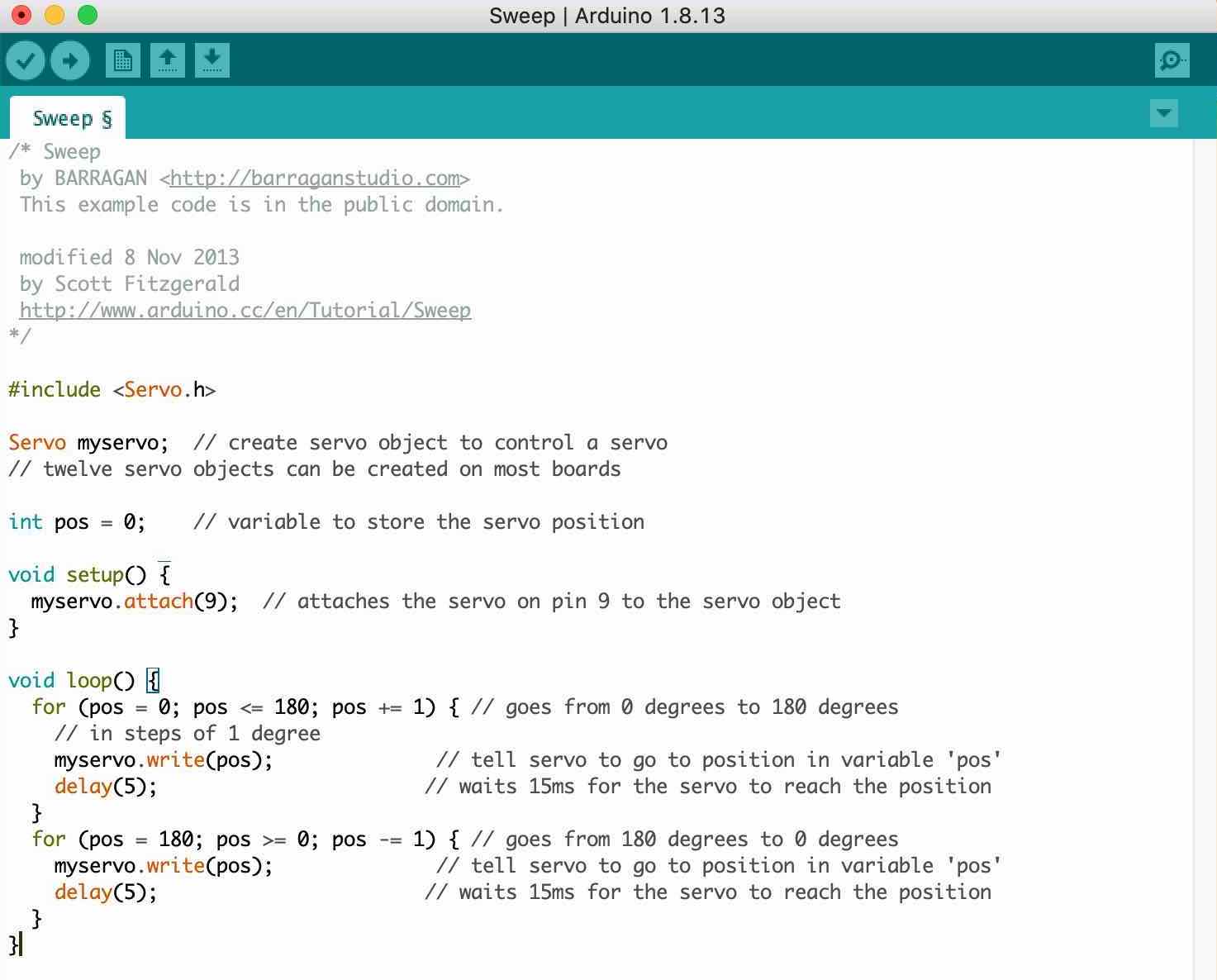
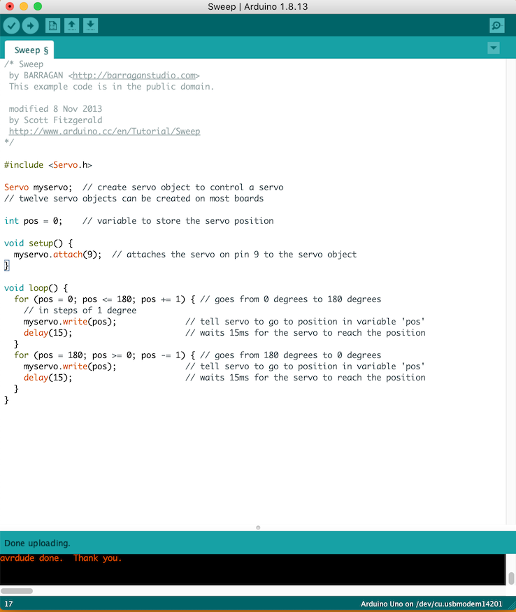
I then changed the delay of the servo so that it was going 5ms rather than 15 ms which meant that the servo moved quicker. Because it is in a 'loop' this means that the servo will keep going until if it was connected to a battery and the battery died or I disconnect the circuit.
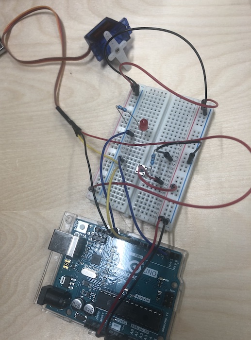
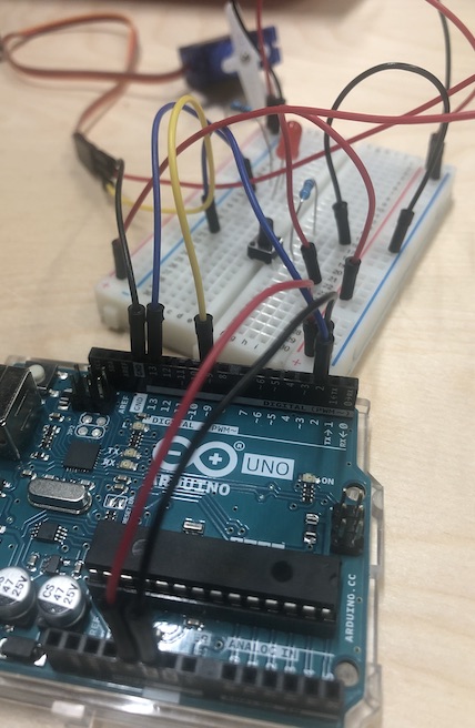
Therefore I'm now going to make a circuit board with a servo motor, a button and a LED so that I can see how it works in a whole. This means that to program this I will need to get both the button and servo motor to come together and work together. So when I press the button the LED will turn on as well as the servo then moving when it turn it on and off.
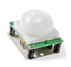
Followed this tutorial to understand to to get a motor sensor to work
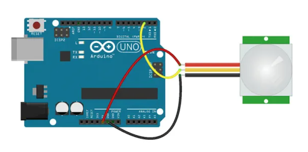
This motion sensor wasn't the one I ended up using as it sensors infared light which doesn't work for what my project is because it is a bottle cap. I have now been using an ultrasonic sensor as this detects motion rather than infared.
So when I then got to the point of being able to get these items to work but individually I then decided to get the button and servo to come together.
For my final project I am making a childrens mobile and what it to spin when it senses movement from the baby. I am going to try out a servo motor so that when the sensor detects movement the servo motor will move and course the mobile to jiggle.
Andrew helped me to get to this point as I have never done anythign like this before, from following the tutorials I have learnt many things but not how to hack two programs together.
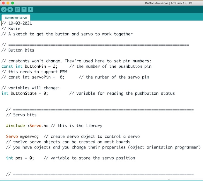
So the way me and Adnrew did it was to get the button and servo arduino example up and started by going through the button example and getting rid of parts we did need. So I wasn't using an LED so all the LED parts to the button I got rid of. Making sure to add // in the front of all the comments I was making to let me know what I was doing in this section of the program.
Below is me splitting the 'button bits' and the 'servo bits' so I can see what each parts - again adding comments to keep track of what I am doing.
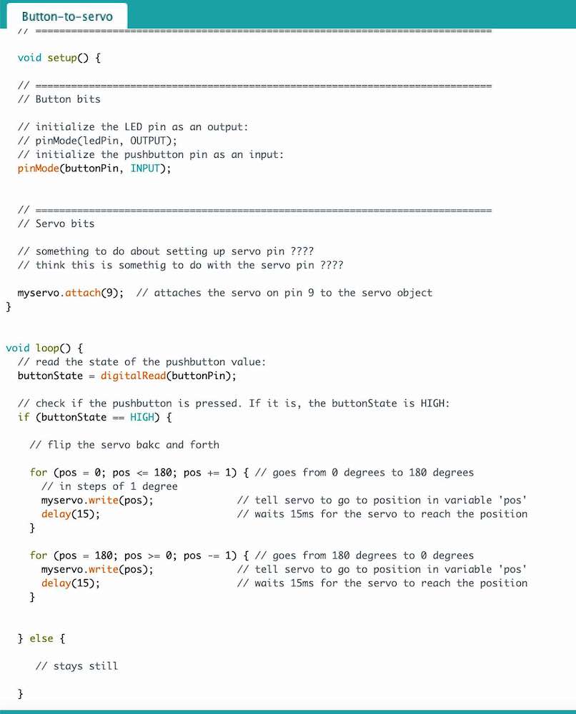
Now with the void setup I also split up the 'button bits' and 'servo bits' so that I could see what each one was doing. We noticed that the servo has it almost going backand forth but I do need to alter the degrees a little bit to work better for what I am tryin gto achieve.
At ths point Andrew my tutor had to leave on paternity leave... so having never done anything like this I thought starting with the 1614 would be the best start, wish me luck!
I start by reading the AtTiny1614 data sheet but then when I realised that we didn't have a programmer to work with it I thought it was best to change the chip. The reason that this chip wasn't going to work me for was because it had a two header so this doesn't work for the programmer we have (ATmel-ICE), this is why I changed what I was doing.
But I did give this one a little read to understand where I should be connecting my components to get the correct outputs for each pin.
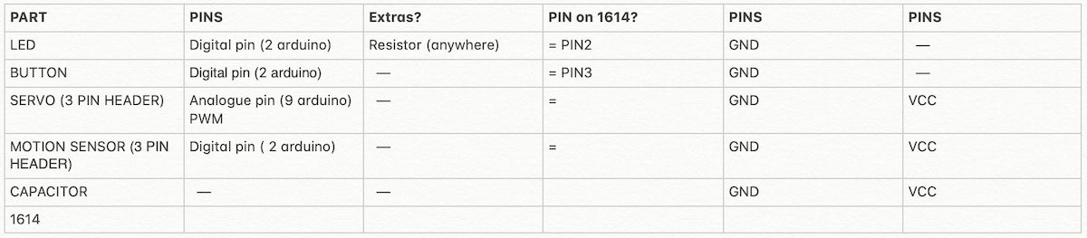
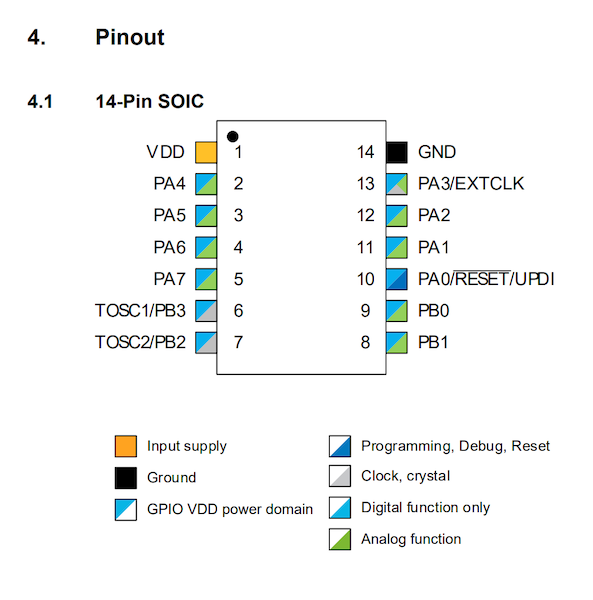
I got very confused by this pinout image, Jonny ended up helping me to understand it as he said the 'GPIO VDD power domain' is open to all but also pin 2, 3, 4, 5, 12, 13, 9 and 8 are all digital and analogue which is great! These are the pins I am going to use to attach to my board.
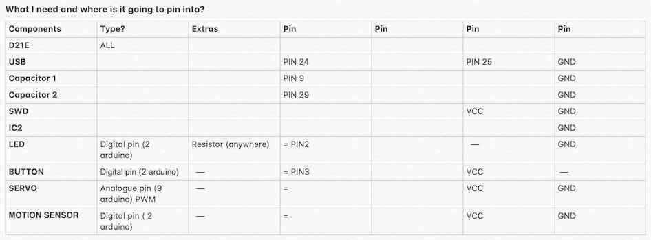
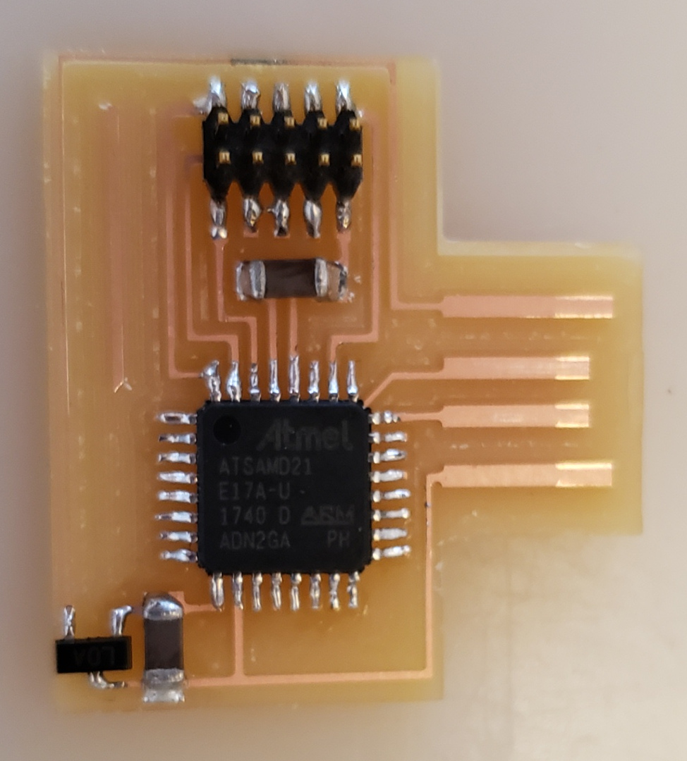
I ended up changing my chip to the AT SAMD21E17 so I started reading the AT SAMD21E17 data sheet
What I quickly realised that actually reading the data sheet is much easier to do when you have started the schematic.
I then looked up Neils board for the AT SAMD21E17 -wk8 Fab Academy list the chips are near the bottom with an image of the schematic, image of the parts on the board and videos extra parts you will need to get the board to the programming stages.

I first realised that when reading the data sheet was that this one was for a few different chips. I started by finding the correct chip which was teh 32 pin one with 8 on each side, this matched up with the one we have in our lab.
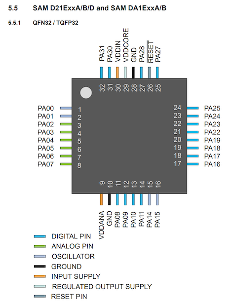
To be honest I find data sheets rather confusing as I'm not sure always what I am looking for, what I found useful was to go to the finder of the page (cmd+f) and search the information I was looking for. I espcially did this when I was looking for which pin the components should be connected too.
Over the next few months I will start to understand them more and I understand how useful they are, I see them as the instructions to the part and to get the most out of that part is to look at what you are needing and check the data sheet to see if they are the correct chip for you.
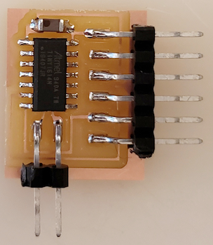
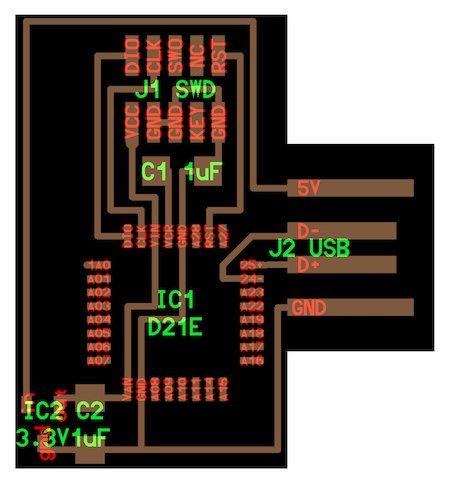
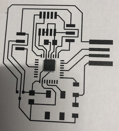
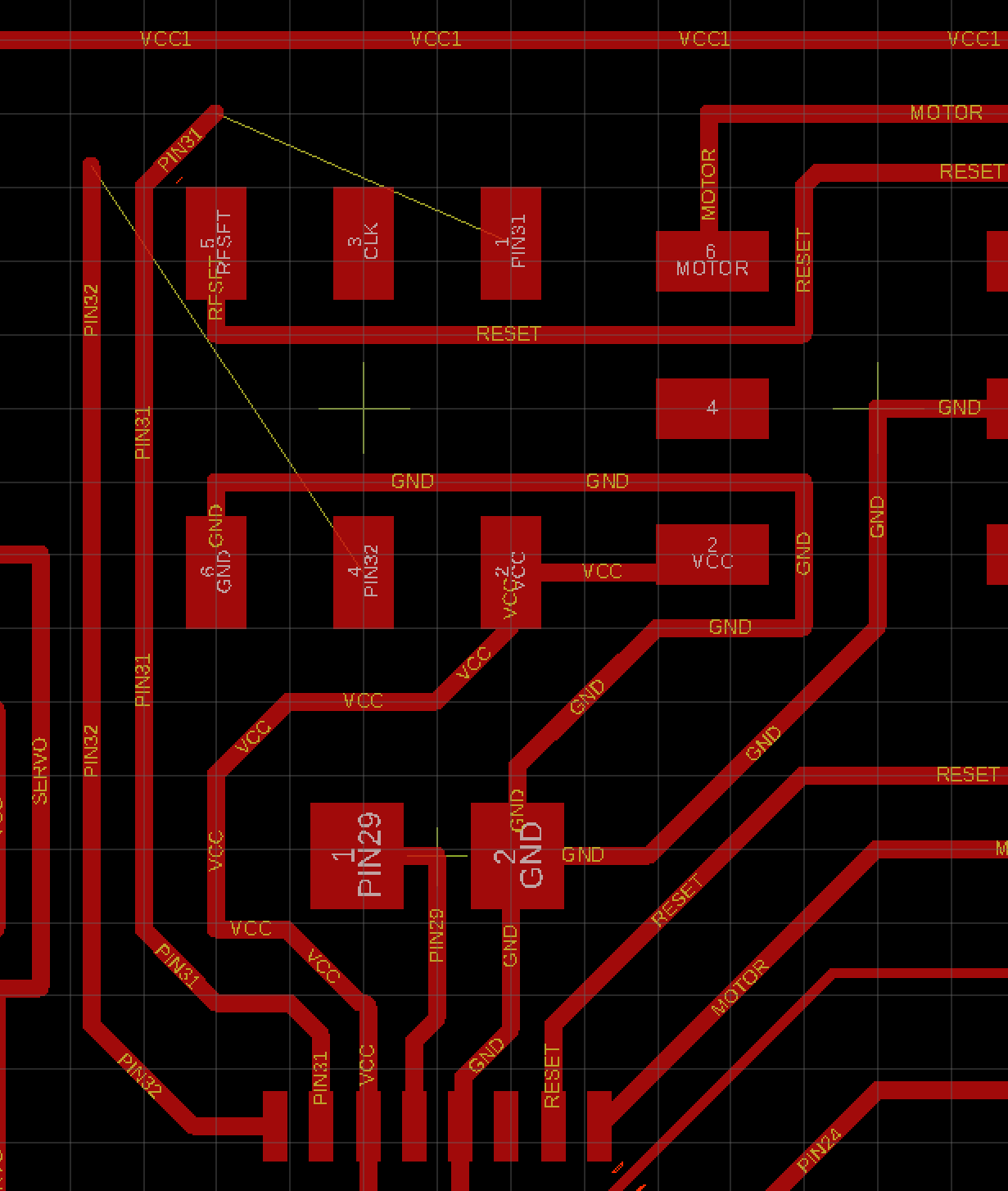
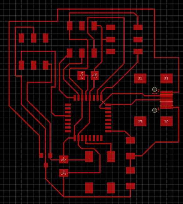
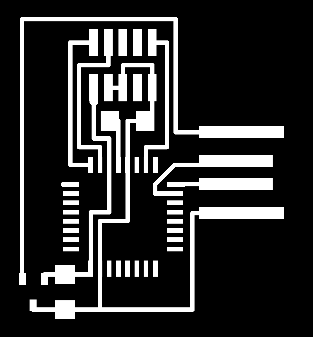
Annoyingly I did take enough screenshots of me making my board in eagle, but I can explain what I did and you can see the changes via the board png that I would cut.
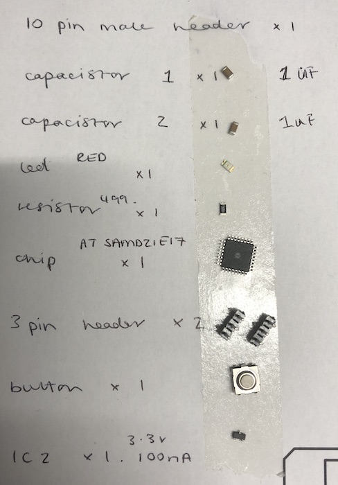
I thought I'd add an LED, button and two three pin headers so that I could use this board to try out my servo motor.
I realised that my three pin headers where the wrong way around in my board and needed to use ones that had spaces between them. I decided to just use a 6 pin header and ignore the pads I didn't need as this was the easiest way to get a 3 pin header footpath.
Changed the traces and the pins for the usb connector as when talking to Jonny he thought it was best not to change where these were connected to as we couldn't figure out if these had significant output or inputs for the UBS port. I just changed the size of the trace and also told the trace to ignore obstacles so it could get through the gap.
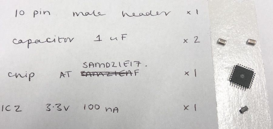
We also discovered we do not own any 10 pin make headers so had to change it to a 6 pin header. This took a very long time and getting to understand where the new pins should go
I did look at the Atmel user guide: link here but unfortunatly I didn't quite understand what I was reading at the time. At the end of this page you can see more about what I learnt after I had spoken to John and realised what each part of the booklet meant, each week I am understanding more what to look out for in each booklet.
Changing the 10 pin header in eagle and reconnecting the traces - I was struggling to get this all connect but I did get there in the end just had to rotate the header a few times to get it right.
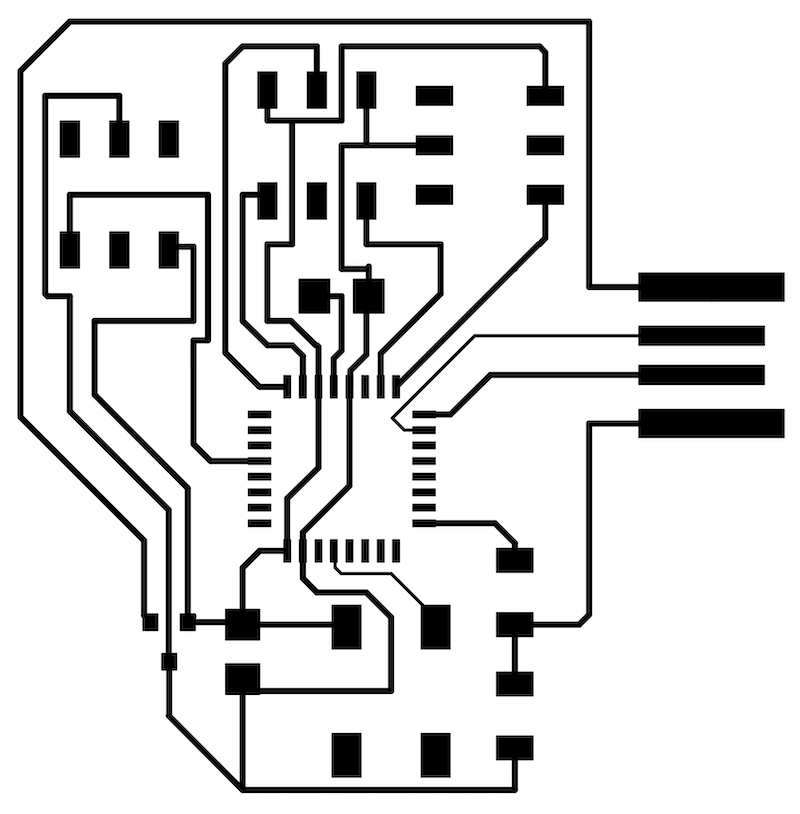
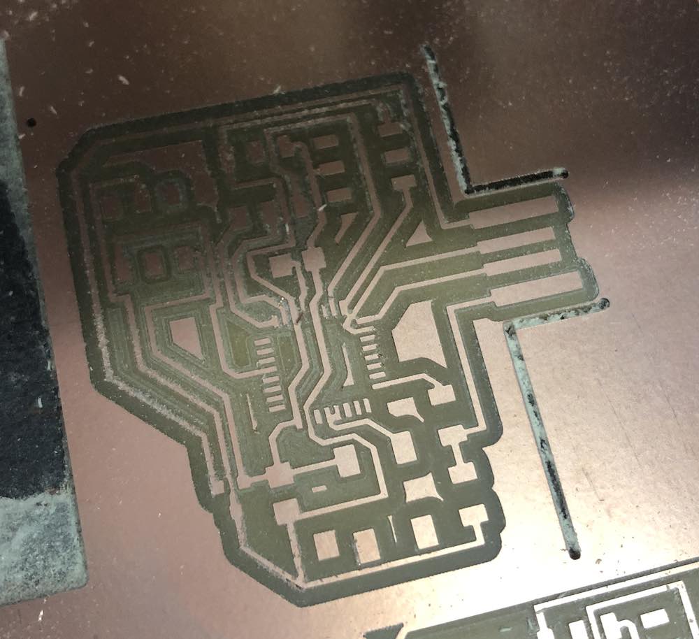
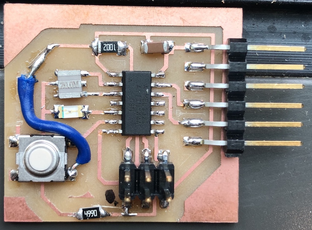
So if you look at the traces below you can see that the copper is very close to the edge so therefore the traces where not cut porperly for this board.
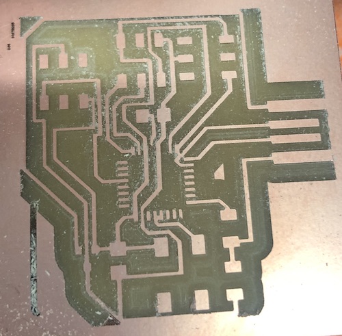

I started to cut this one out and got to the very end started to do my outline and then... realised the outline I had cut out was too close to the edge so the whole thing would have ended up short circuiting because I have made the file too close to the edge.
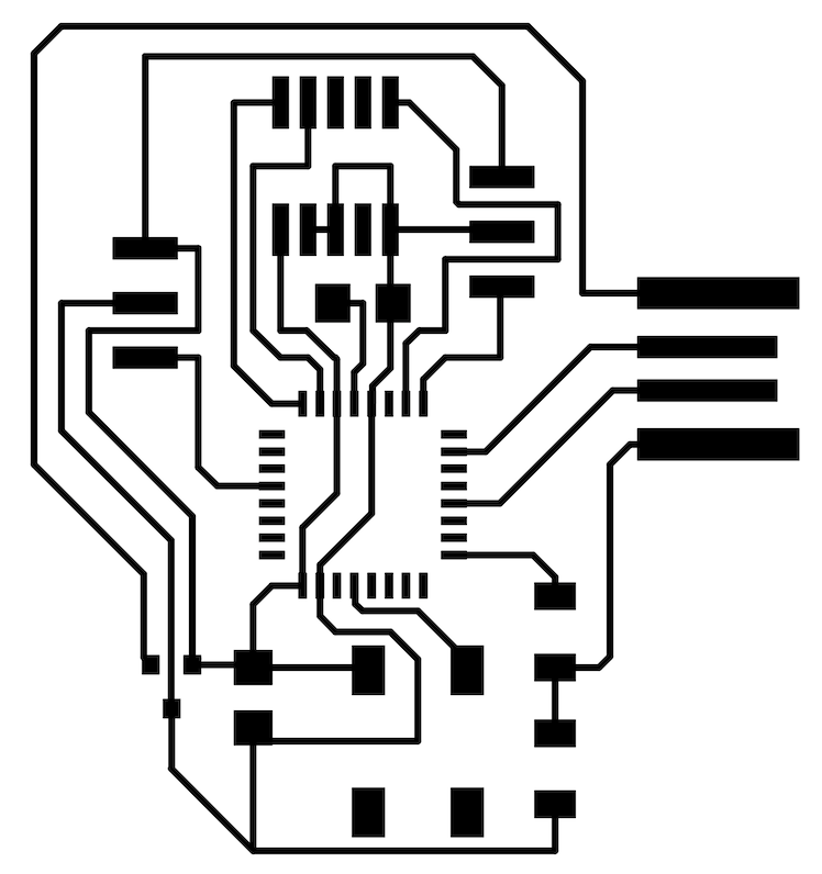
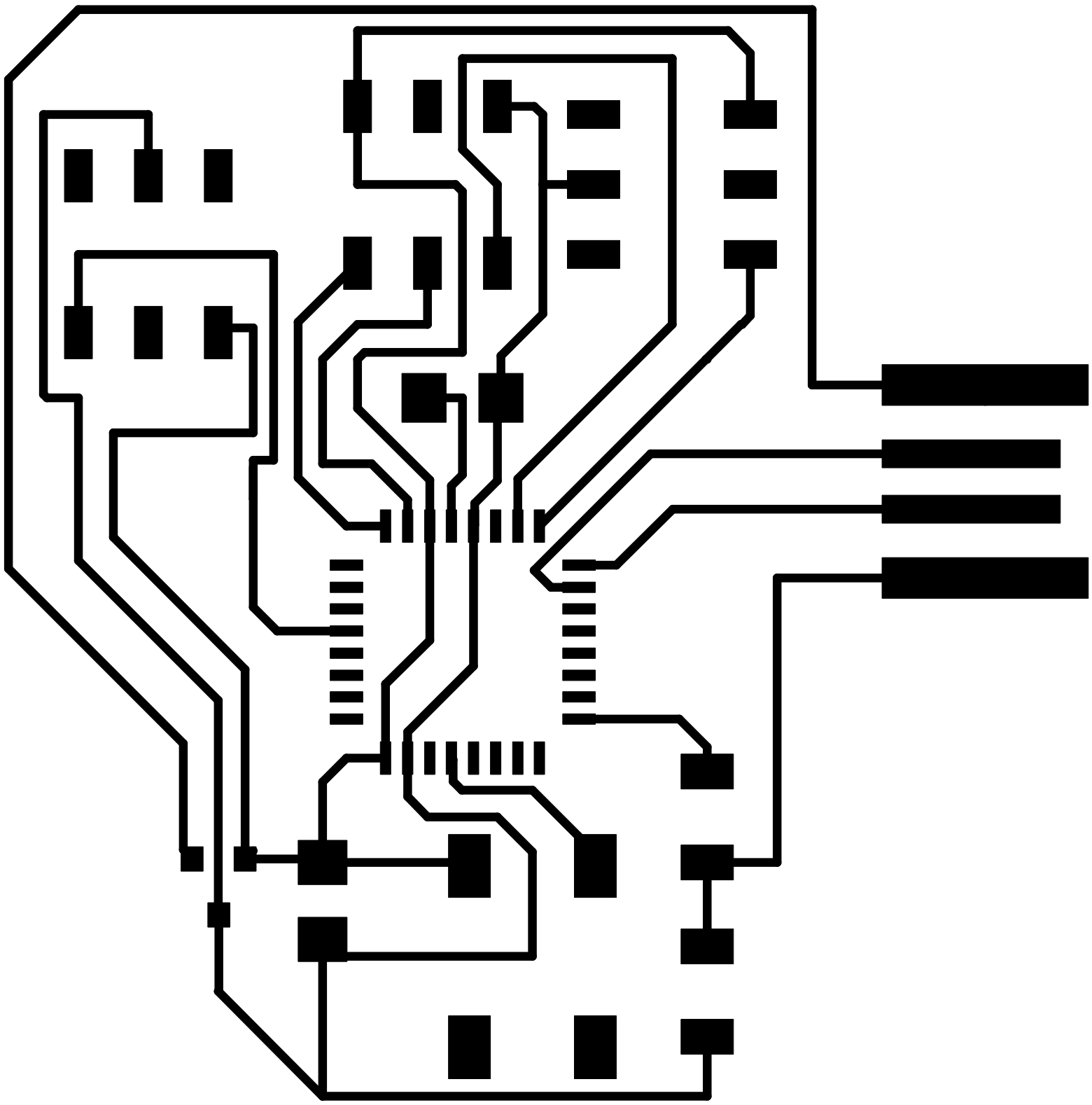
4 and 5 are the same just had to remake it as I had made the size wrong on the png when printing as you explained above ^^
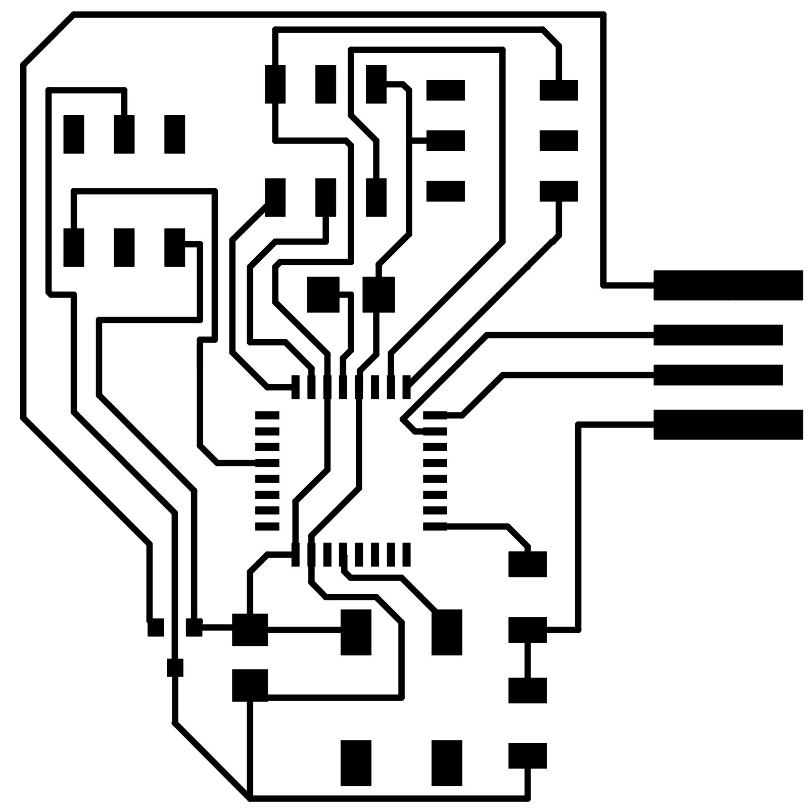


Changed the thickness of the traces so that it would cut out correctly around the chip.
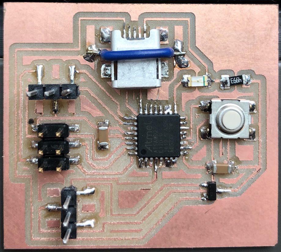
I then just couldn't get the USB port to line up correctly with the outline which was really frustrating me. I ended up just making it with a mini USB port as this would hold down better and be more reliable in the future.


Don't know if you have noticed but the I have placed the footprint of the USB the wrong wya around... yes this is something that I didn't notice till I was soldering it on but I will show you my (I think) clever hack to not have to remake the whole board again.
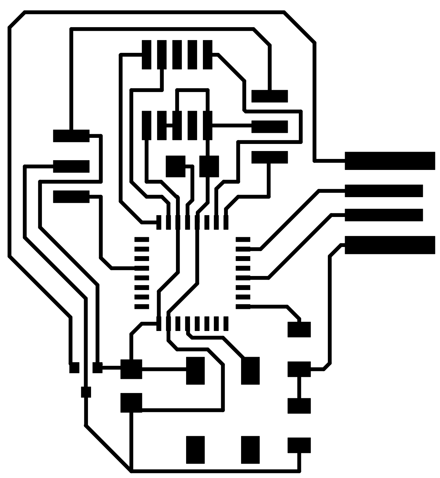
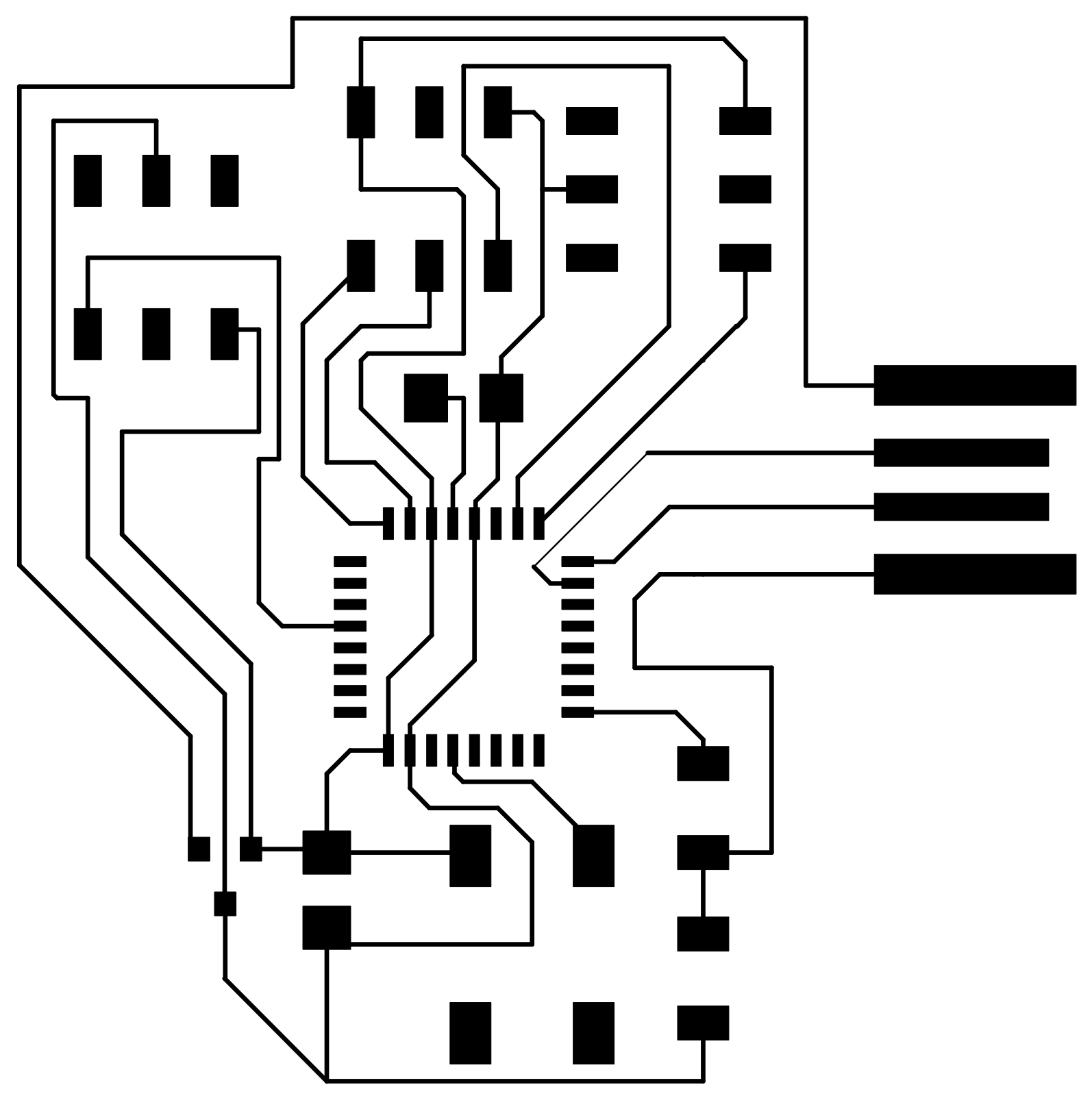
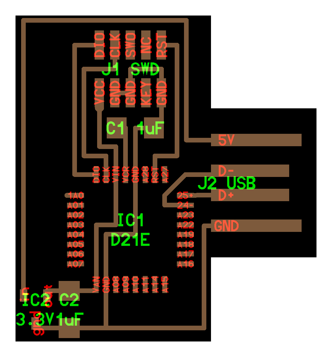
Here is the board in eagle as well as the final schematic of the board.
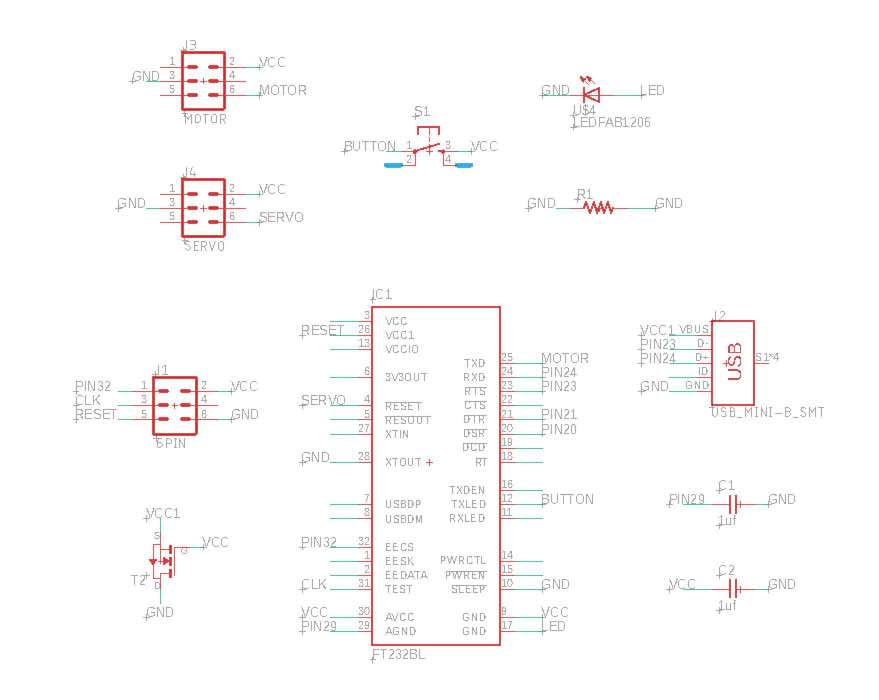
In the end this worked a lot better with the square outline rather than trying to line it up with the USB port.
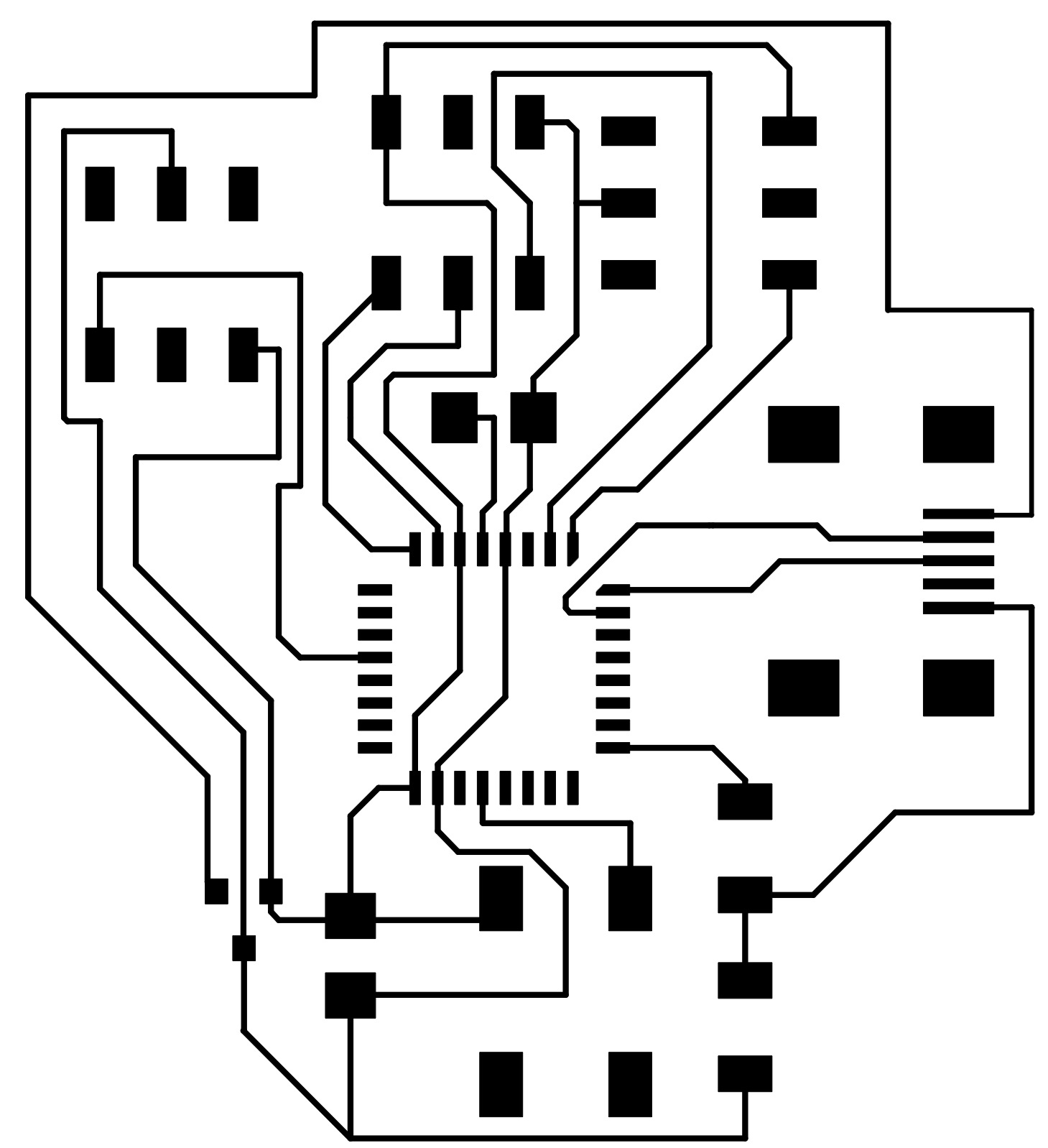

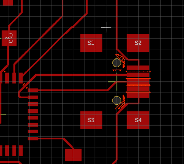
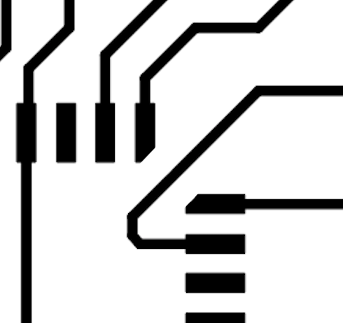
I also ended up editing the footpoint on the chip so that the milling bit would cut through the copper gap between teh traces and pads.
I realised I had placed the UBS port the wrong way round on the board... yes yes I know should always check but at this point I was tired and was about to explode. All the other parts went on smoothly with little issues, the chip none of them where connected and all the other parts were the correct way arouhnd.
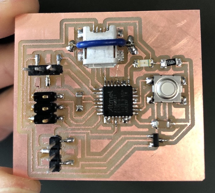
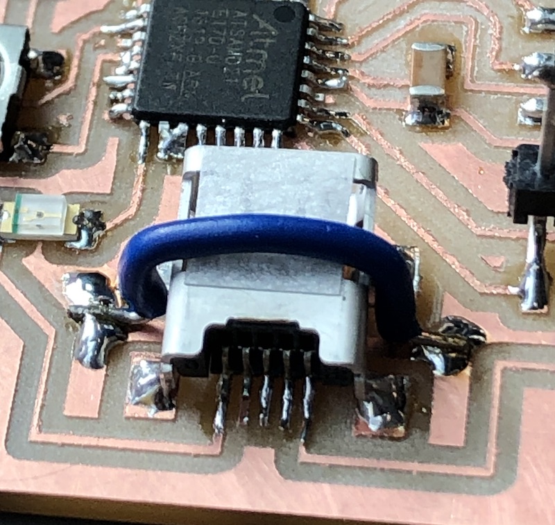
What I did was place it the correct round so that the pads and the pins matched up, I then realised I needed to lift it up a little just so I could get the cable in. But if I did this over and over the traces would end up coming off the board with the movement. So I put a blue wire over the USB port so that it couldn't move heigher than the blue cable which worked veyr well and made the component very secure.

So at this point...
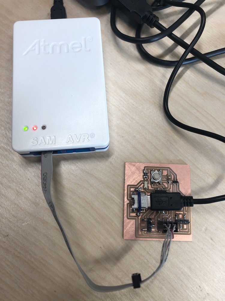
I plugged my board into the Atmel programmer and the light came on which was possitive.
This is my step by step of what I did when I was following this students processes of programming their board with the Atmel-ICE progammer. They were programming a different board so I took in to concideration of each step and what I would need to change.
I followed this old student: here's the link
DOWNLOAD edbg: here's the link
Unzip it
Moved to home directory
= worked
Type
    $ make all
    make: *** No rule to make target 'all'.  Stop.
= did not work
Install hidapi: here's the link
Run this in terminal app
$ sudo ruby -e "$(curl -fsSL https://raw.githubusercontent.com/Homebrew/install/master/install)"" < /dev/null 2> /dev/null
I got:
      ==> Checking for 'sudo' access (which may request your password).
      Don't run this as root!
Then type
$ brew install hidapi
I got:
    "Updating Homebrew...
      ==> Auto-updated Homebrew!
      Updated 1 tap (homebrew/core).
      ==> Updated Formulae
      Updated 1 formula.
      Warning: hidapi 0.10.1 is already installed and up-to-date.
      To reinstall 0.10.1, run:
      brew reinstall hidapi"
= this is done! - you can now use 'hidapi'
Now type
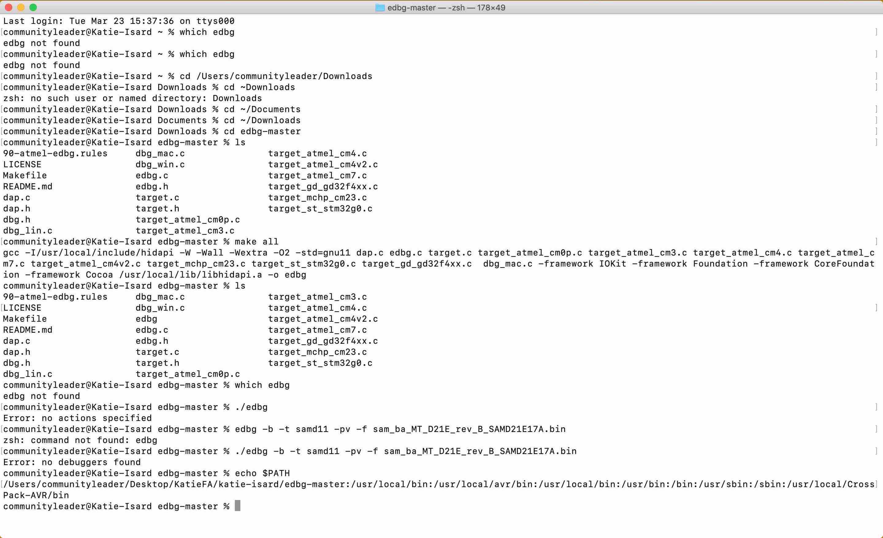
    $ cd edbg-master
     Which means you are now in the pwd 'edbg-master'
= this worked
Now type
$ make all
I got:
    gcc -I/usr/local/include/hidapi -W -Wall -Wextra -O2 -std=gnu11 dap.c edbg.c target.c target_atmel_cm0p.c
    target_atmel_cm3.c target_atmel_cm4.c target_atmel_cm7.c target_atmel_cm4v2.c target_mchp_cm23.c
    target_st_stm32g0.c target_gd_gd32f4xx.c  dbg_mac.c -framework IOKit -framework Foundation -framework
    CoreFoundation -framework Cocoa /usr/ local/lib/libhidapi.a -o edbg
I have made another page which has all the issues that I came across when I was trying to programme this board. It is very long and thought by having on this page would make it easier to understand where I went wrong.
John who is a vertual student I messaged him to ask him what I am doing wrong.
Turns out:
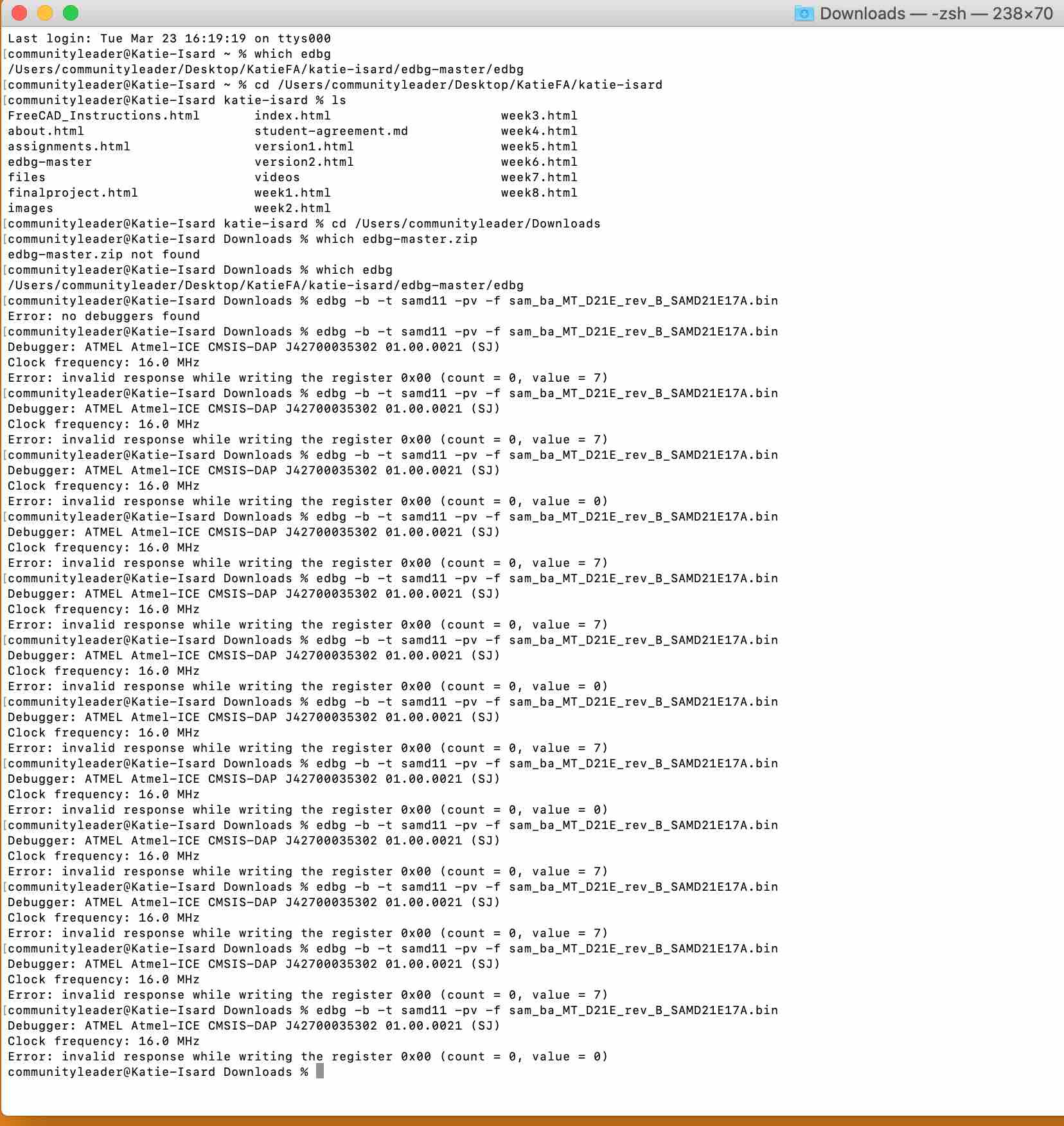
BUT he did end up helping us get past the difficulty we were having and by the end of him tell me what to do I managed to get my board to come up but then an error has come up. Probabyl because we changed the 10 pin header to a 6 pin header but then could be many other reasons!! I look forward to trying to get to the bottom of this in weeks to come but for now I am done!! haha
We also placed Jonny's board into my terminal to see what his would do and strangly
I got:
Error: invalide responce while writing the register 0x00 (count = 0, value = 7)
Jonny got:
Error: invalide responce while writing the register 0x00 (count = 0, value = 0)
It would change and let us know that for Jonny's - one way would come out as value = 0 and when you rotated the 6 pin header it would turn the light off and come up as value = 7.
I now need to check everything on my board but to be honest I think I will start again and buy some 10 pin headers and see if I can do it this way rather than hacking and coursing more trouble.
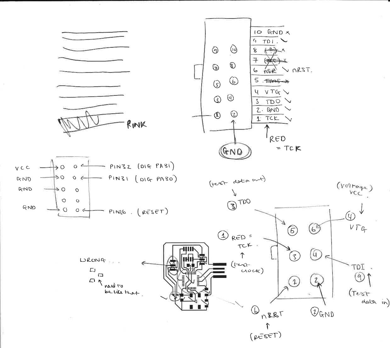
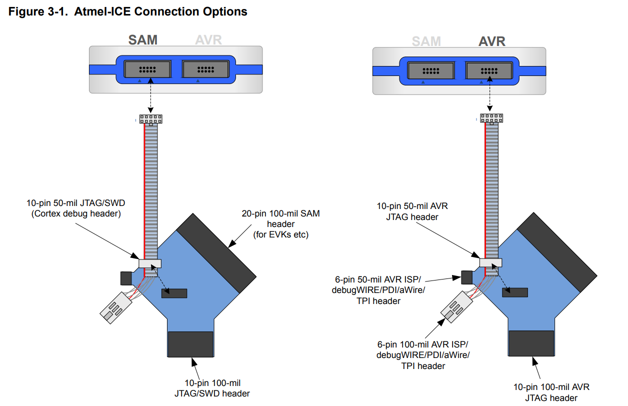
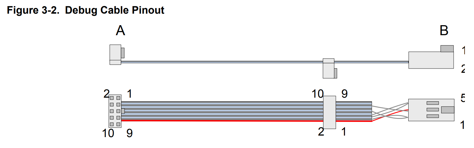
So we tried to understand what pin goes where and how the 6 pin header connects to the 10 pin header.
Looking at both of these images I knew I had to use the SAM port as this is what it said in the programming stage of this wekk. The issues was I just didn't understand what I was reading.
Now I had done the assignment and tried to
Source for Button Arduino sketch:
  // constants won't change. They're used here to set pin numbers:
    const int buttonPin = 7;     // the number of the pushbutton pin
    const int ledPin =  8;      // the number of the LED pin

  // variables will change:
    int buttonState = 0;         // variable for reading the pushbutton status

  void setup() {
      // initialize the LED pin as an output:
    pinMode(ledPin, OUTPUT);
      // initialize the pushbutton pin as an input:
      pinMode(buttonPin, INPUT);
   }

  void loop() {
      // read the state of the pushbutton value:
      buttonState = digitalRead(buttonPin);

      // check if the pushbutton is pressed. If it is, the buttonState is HIGH:
      if (buttonState == HIGH) {
        // turn LED on:
      digitalWrite(ledPin, HIGH);
   }  else {
      // turn LED off:
      digitalWrite(ledPin, LOW);
   }
  }
As I showed at the beginning of this page I managed to get my board from week 6 to work, I am not in week 16 and as I haven't managed to get this board working I have reuploaded the button sketch from Arduino onto this board to work again.I have also learnt how to add videos so this is a video of it working now as well. ENJOY
This week has been really really hard for me, having never done anything like this before other than week 6 I have had to learn a lot in a short amount of time. I have really enjoyed it and can't wait to understand all the errors and am able to figure it out more in the future.