3. Computer Aided design|Week 2
This week I worked on CAD software to get the skills to do my next final project idea.
This Week’s Objective
Use different tools and techniques to design in 2D & 3D
Tools/Software Used in This Assignment
Before I start with design Software and types, I’m going to explain important things about images and files and how to handle them within your program.
JPG VS PNG
This was my conclusion of the topic:
| JPG | PNG |
|---|---|
| JPEG uses lossy compression algorithm. | PNG uses lossless compression algorithm |
| May lose some image data | High quality |
| Generally smaller in size | Generally larger |
| Does not supports transparency images | Supports transparency |
| Used in photography creation | Generally used in icon |
For more details: This tutorial helps me to understand the difference between them.
2D Design :
Inckscape introduction tutorial:
Conclusion:
In this tutorial I was talking about the introduction of Inckscape-2D software and how to draw a circle, rectangle. How to change the scale of them. Changing the colors of the shapes and the outlines, etc..
How to make a Gear Box in Inckscape:
Conclusion:
I made a tutorial about how to design a Gear Box in Inckscape these are the highlited points:
1- Draw a “star” From the list on the left, then you can change number of the “corner” of the star from the upper shortcut.
2- draw a circle, then “duplicate” it from “Edit”.
3- To remove the sharp edges hold down “Shift” on both star and circle then click on “Intersection” from “Path”.
4- to make any two shapes and above together click on “Union” from “Path”
5- To make a hole in a shape click on “Difference” from “Path”
Section No.1: Raster vs vector
In this section we will talk about the Differences between Vector and Raster graphics
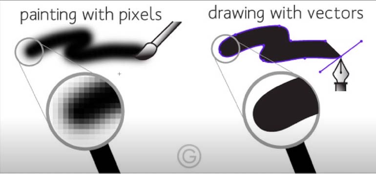
Reference and this is my conclusion:
The image in a Raster format(Pixels) has been reduced in quality when they change in size or when they are zoom in/up. But the Vector image It remained with lose any pixels.
## Vector vs Trases tutorial :
Conclusion of the above tutorial:
| Raster | Vector |
|---|---|
| Composed of pixels | Composed of paths |
| Refresh process is independent of the complexity of the image | Vector displays flicker when the number of primitives in the image become too large |
| Raster graphics can draw mathematical curves. polygons and boundaries of curved primitives only by pixel approximation. | Vector graphics draw continuous and smooth lines. |
| They occupy more space which depends on image quality. | They occupy less space |
The table above shown the difference between Raster and Vector.
So after learning the difference between them, let’s see examples of the file extension:
| Raster | Vector |
|---|---|
| Png | Svg |
| Cdr | Jpg |
| DXF | Gif |
| Psd |
The table above shown examples of file extension.
This week was dedicated to exploring and learning many CAD tools.
3D Software’s:
Rhino | Parametric
I have collected the most important things that the program can do
Why I chose Rhino to learn ?
• It is a professional tool for surface modeling.
• gives a huge Capabilities for product designers that related to my interest.
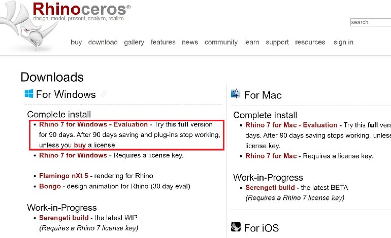
• It’s a affordable for student and teachers, so you can use the free license for 90 days.
• Fully compatible with 3D printing, CNC machine, and other software like SolidWorks and Inventor.
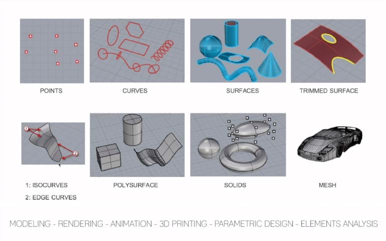
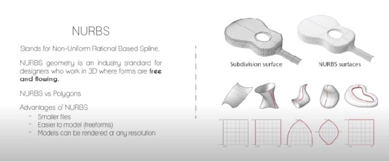 This is the reference and my conclusion is :
The image above shown that Rhino is used NURBES surfaces that easier to model a curvy model with less meshes and size.
Let’s start by downloading the software through the free student license for 90 days from the official website.
Where Rhino is used?
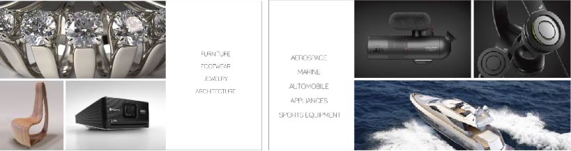
The image above shown the top application of Rhino
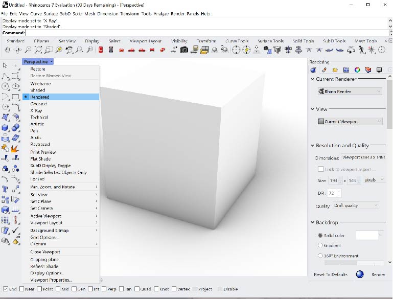
first impression of Rhino, was that it is a simple software that provides many tools that facilitate the design of difficult matters with quick support tools for beginners, and I liked it
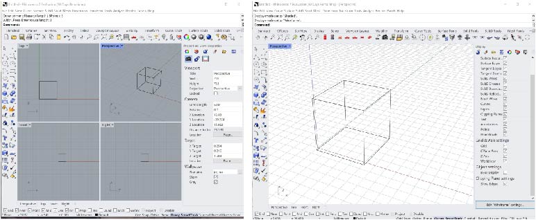
I designed this cube with the “polyline” by typing the coordinates (X,Y,Z) in the Upper commands. It allows you to make what you want by typing there.
Rendering
Rhino provide fast-easily rending to show your work in better way.
Here I will show you my project in Rhino in just after two hours of learning the software.
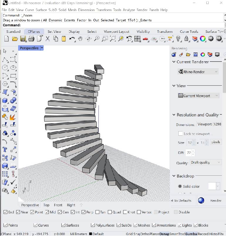
I designed a spiral staircase through “Arraypolar” command.
Because of Rhino is a master of jewelry making, I made my first “Ring” that I will show you in this video:
Conclusion: This was the first time that I designed a “Ring” on Rhino, and I discovered that is amazing software to do it right there. In this tutorial I used “ArrayPolar” by typing in the command list to make many duplicate for cylinder to make a cut pat in the original one.
CAD File: Click here to download it
Blender(Geometric/Parametric):
Blender is a free open source 3D software. It can be used for almost anything; modeling, sculpting, texture painting, animation, etc..
I Chose Blender especially to learn the “Sculpting” because of the massive tools that it provides.
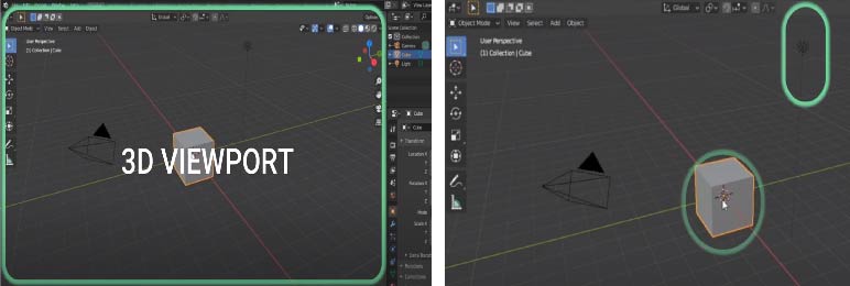 Here we can see the Home Page that it includes the model, camera,the light , and the modifiers of the software.
What is the difference between Perspective/Orthographic?
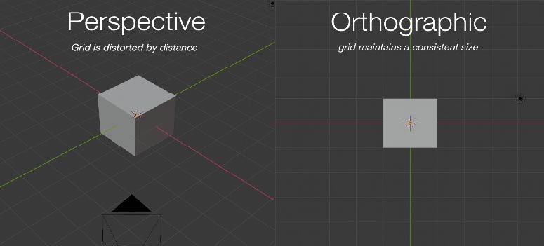 * Perspective: (objects further away appear smaller).
- Orthographic: Objects are the same size no matter how far away they are. This is used in most 2D and “fixed viewpoint”.
 Perspective and Orthographic representation in Blender|
Reference of the GIF from here
Perspective and Orthographic representation in Blender|
Reference of the GIF from here
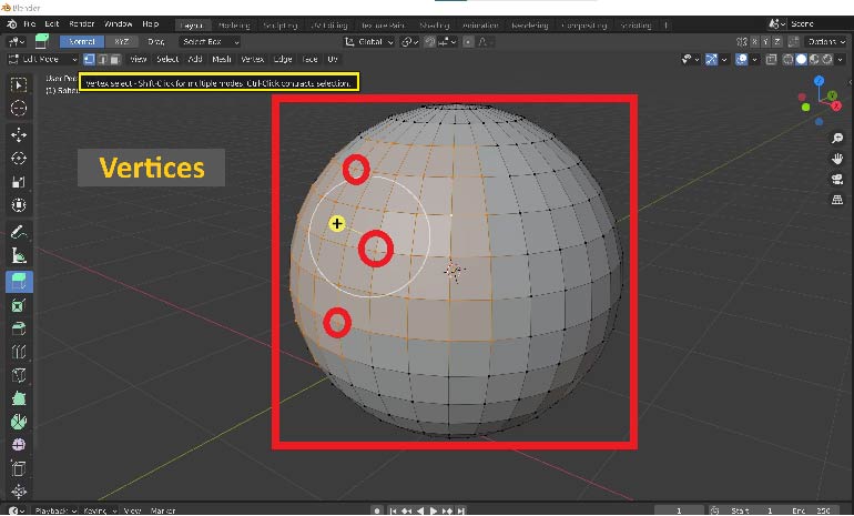
Another advantages of Blender (Vertices):
I learnt how to edit and Selecting all Vertices, Edges, and Faces. This feature is difficult to find in other software.
I have learnt the basic of Blender in 20 MINUTES by this tutorial:
Sculpting tool:
By Blender I can now make a simple sculpting for characters and the complex models using “ Sculpt mode” By selecting “Grab and Snake Hook Brush” This the first shoot of me while sculpting to make a “Dragon”
CAD file : Click here to download
3D Model:
Conclusion: This was the first time that I designed a “character(Dragon)” on Blender, by using the sculpt mode you are able to design incredible thing there with many tools to do your idea whatever it looks. you have to use the mouse to Digging and pulling.
SolidWorks [Parametric]:
I have used “SolidWorks for two years ago with good experience and it’s an amazing mechanical and modeling software that have a lot of tools can do almost everything especially in solid bodies, Sheet metal, and power surfacing. This week I recorded some of tutorial about “Simulation/Animation” and “Rendering” that help you if you want to go farther:
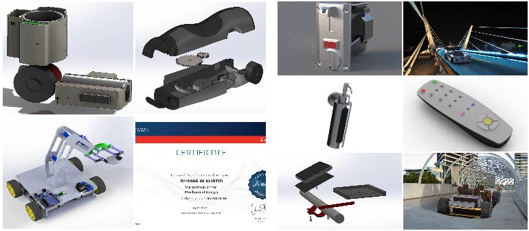
the image above took from my gallery In several domains, most importantly in Product design, mechatronics, Reverse Engineering , and surfacing.
Firstly, Sketching and extruding :
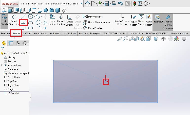
In the shortcut bar tool there is two important stuff you should know about them. First one is “Sketch” that allow you to draw in 2D . Here I made a rectangle from the origin.
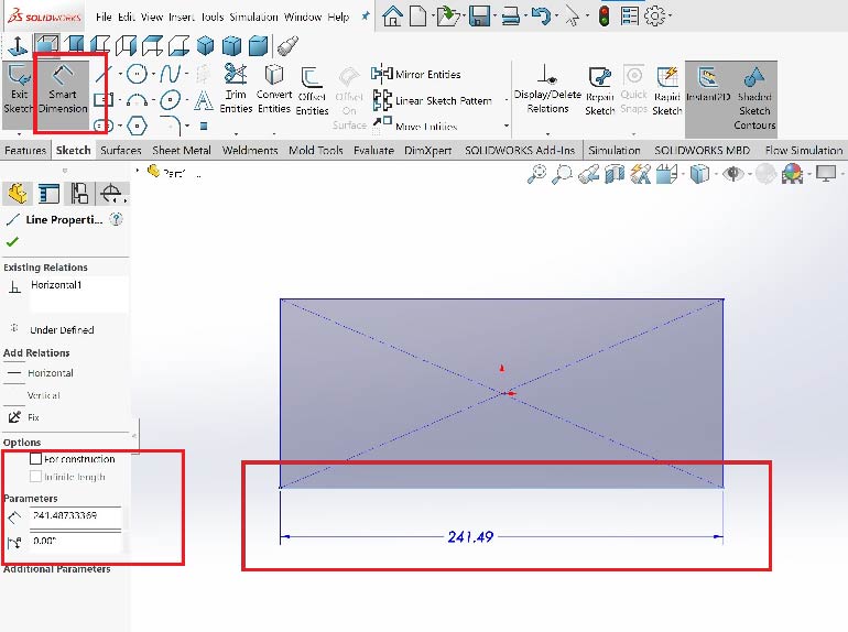
SolidWorks allows toy change the dimension after finishing up your model using “Smart Dimension”.
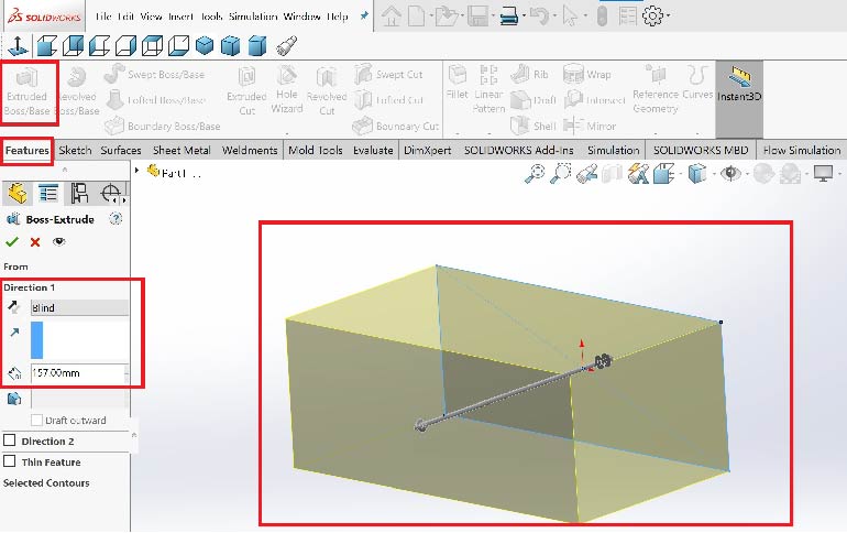
The image above shown a 3D model of a box. By clicking on “Feature” then on “Extrude Boss” you will convert 2D model for a 3D .
Revolve Boss :
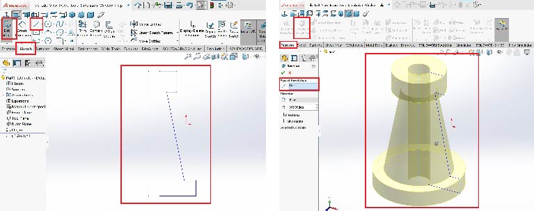
There also a wonderful tool in SolidWorks called “ Revolve boss” it usually used for the cylindrical shapes that allow you to make it in a short time, try it!.
Assembly, Simulation, and Animation tutorial:
Conclusion:
In this tutorial I was talking about Assembly mode, how to use the toolbox library (that is offer a lot of useful parts). how to make a simulation for a gearbox with a virtual rotary motor. and in the end of the video how to animate your design automatically “Motion Study”.
Changing materials, the appearance, Rendering Tutorial:
Conclusion:
In this tutorial I was talking about how to change the materials and the colors. How to edit the enviroment, the camera, the light, material in Rendering mode “SolidWorks Visualize”
Final project:
[Posture Corrector with Smart Sensor Vibration and Aalrm] :
Box_Upper& Lower 3D printed |Rendering :
Concept of the design:
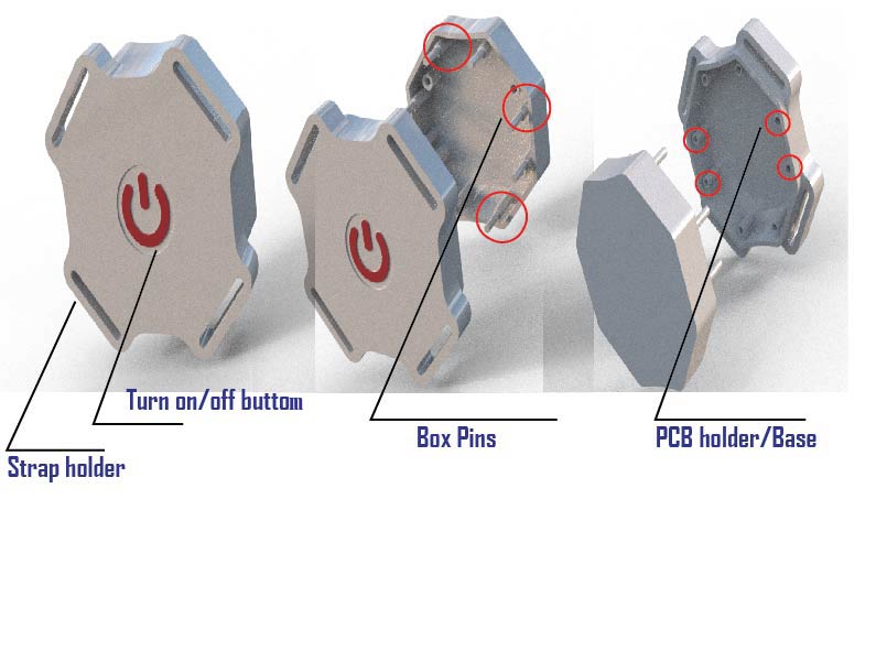
The image above shown the box consist a Turn on/off button, PCB pins”Base”, strap holder, and box pins(without screws).
CAD files:
Materials will used in this project :
High strength nylon for the strap + ABS/PETG for the box
3D Viewer:
Useful links/References: