Week 08
Embedded Programming
Group assignment Compare the performance and development workflows for different microcontroller families
Individual assignment Read the datasheet for the microcontroller you are programming Program the board you have made to do something, with as many different programming languages and programming environments as possible.
Group assignment
 - Compare the performance and development workflows for different microcontroller families
 - document the differences and understand better
 - watch tutorials and check Aalto plus Adrian’s site
 - understanding
Basic info
Architectures
- Harvard architectures
- RISC
- Micro controller
Peripherals
| name | explained |
|---|---|
| PA | digital pins (high or low no in between) |
| PB | analog pins - reading out off analog ports is between 0 en 1023 - sending between 0 and 255 |
| PCINT | interrupt |
| ADC | analog digital conversion (both analog and digital) - doesn’t exist for the other version, so analog stays analog) |
| A/D | converts analog signals (usually voltage) obtained from environmental (physical) phenomena into digital format |
| Comparator | compares two voltages or currents and outputs a digital signal indicating which is larger |
| D/A | D/A converters convert digital signals into analog format. |
| Xtal resonator/oscillator | clock |
| PWM | pulse fit modulation also analog, they can read values between -120V en 120V)1 |
| USART | Universal asynchronous receiver-transmitter |
| USB | Universal Serial Bus |
1Potential meter is a controllable resistance, button that controls the resistance via PWM
Families
- LOGIC
- AVR for 8-bit (ATtiny) everything talks in one cycle
- ARM - high end - faster clocks more powerful, standard in circuit debugging.
- Xtensa - integrated bluetooth and wifi
- RiscV - open architecture
Packages
- SOT-SOIC-TTSOP-TQFP-LQFP-MLF, WLCSP, BGA
Cores
- ATtiny, TinyAVR, DxCore, SAMD, ESP8266, ESP32
In System Development
Programming the chip in the board.
-
UPDI (AVR) they read the instructions and send it into the processor
-
JTAG (ARM) EDBG is the best software to use but no longer for MAC
-
boatloader is a programme that loads programs
Programming
We will be programming in C (or CC+) language
Tool chain: takes the programming instructions and converts them into processor code.
IDE An integrated development environment is a software application that provides comprehensive facilities to computer programmers for software development. An IDE normally consists of at least a source code editor, build automation tools and a debugger.
PlatformIO an extension for Visual Code.
I’ve installed PlatformIO within VSCode but didn’t use it yet - should watch the Quick Start
Hostcommunication
- USB - Universal Serial Bus 5V
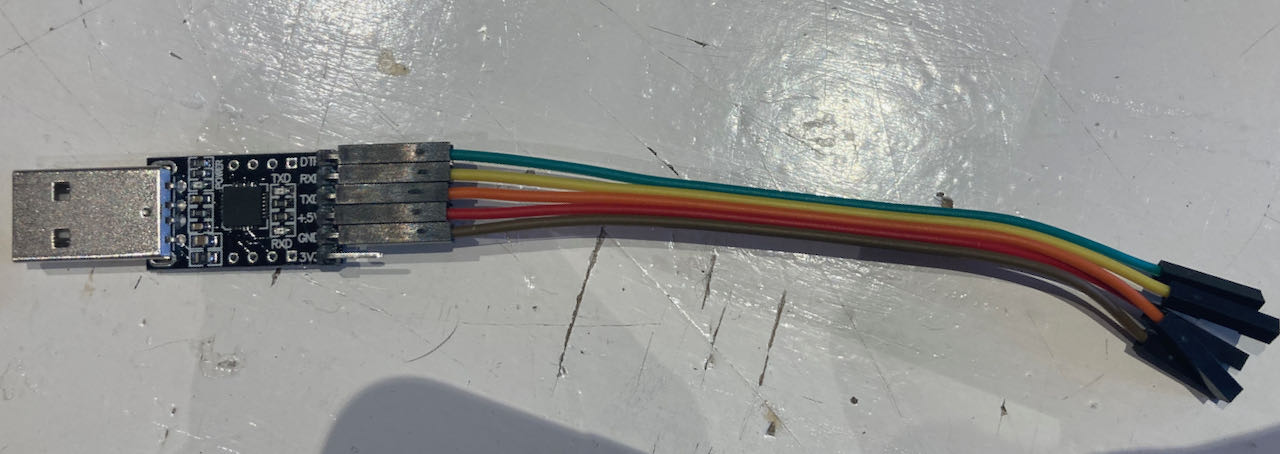
- FTDI - between USB and Serial
Explanation of serial communication is here When using the logic analyser if you cant read the serial communication then maybe the Serial.begin (definition of communication speed)
Analog and digital
Analog
- values in voltage control the on/off
- Natural Phenomena
- Continuous range of values
- Temporally continuous, quantitatively continuous
Digital
- with 1 and 0 tell the pin what to do/be.
- Evenly spaced discontinuous values
- Temporally discrete, quantitatively discrete
Good explanation about A/D and D/A convertors you can find here
Analog Signal to Digital Signal Conversion Methods
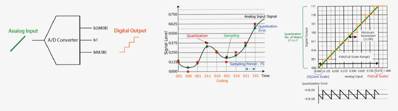
- Sampling is the process of taking amplitude values of the continuous analog signal at discrete time intervals (sampling period Ts). [Sampling Period Ts = 1/Fs (Sampling Frequency)] Sampling is performed using a Sample and Hold (S&H) circuit.
- Quantization: Quantization involves assigning a numerical value to each sampled amplitude value from a range of possible values covering the entire amplitude range (based on the number of bits). [Quantization error: Sampled Value - Quantized Value]
- Coding: Once the amplitude values have been quantized they are encoded into binary using an Encoder.
Difference between computer versus micro controller
Computer has an operating system, IC doesn’t - Program is directly on the IC, not depending on more elements like a computer
I have already made a
- Hello.USB-UPDI.FT230X (UPDI)
- Hello.CMSIS-DAP.10.D11C (JTAG)
- Hello Board with LED, ATtiny412, phototransistor and switch in week 6
- and at the end of this week also an FTDI - Hello.USB-Serial.FT230X
Testing different boards
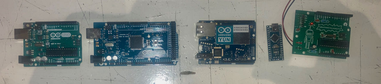
All boards at the Waag that Henk displayed out for us to play with:
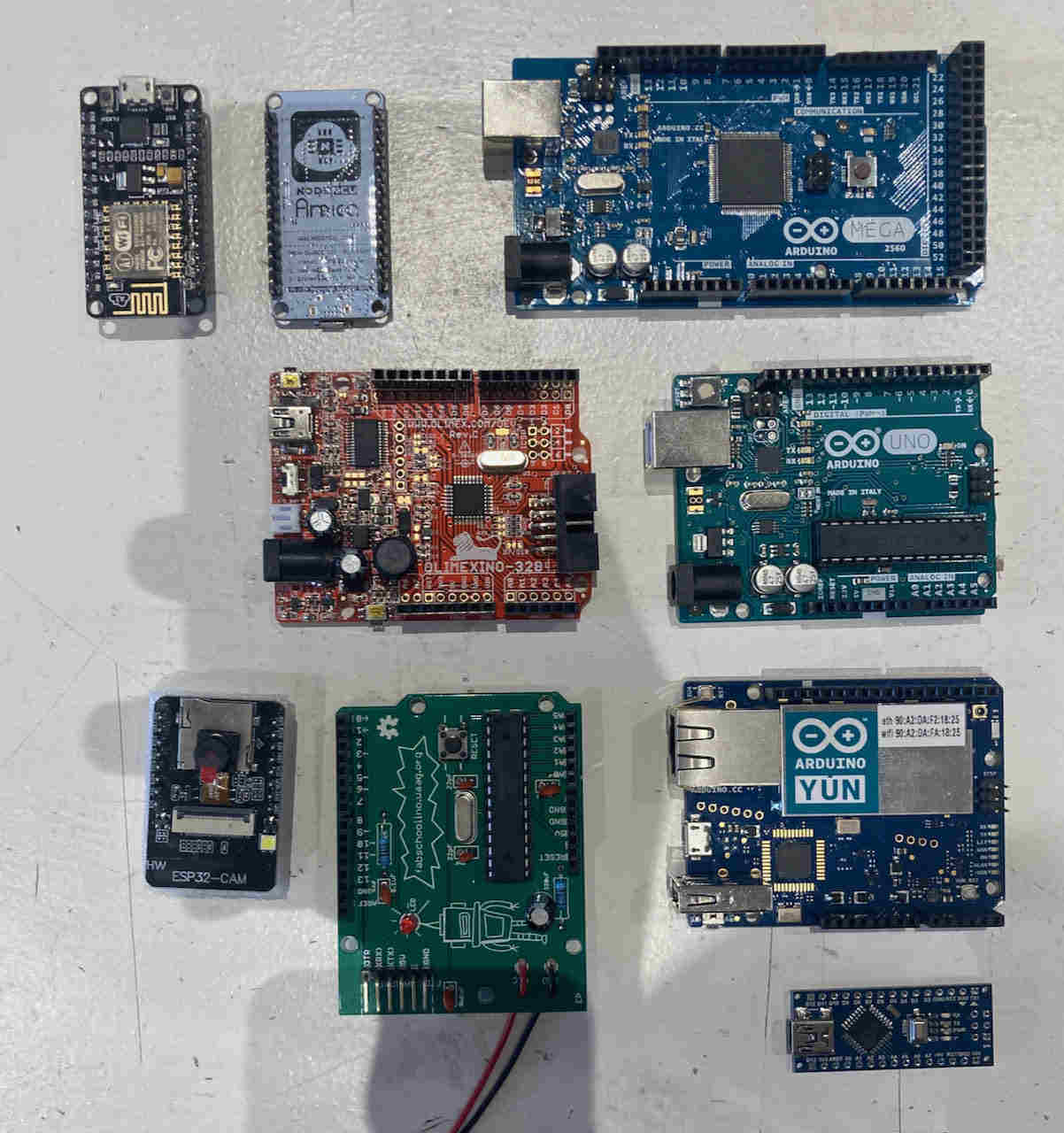
All the Arduino boards that Henk found at the Waag, the one on the right is the one that the Fabcrew made a few years ago:
Basic Arduino info
Arduino consist of:
- set of boards
- installation of toolchains
- set of libraries (very inefficient)
- IDE
- bootloader
- header
The programming is in C, CC+ but with libraries. Arduino uses a fixed library to create the code so it stays big with information you don’t necessary need for what you are programming. CC+ is also big, same problem as Arduino, but C doesn’t have a fixed library so is more lean but harder to know who to program.
Arduino files have a standard setup list:
Arduino use their own number for the pins, which you will have to find out in my case by using google.
- A0 > A5 are the analog ones
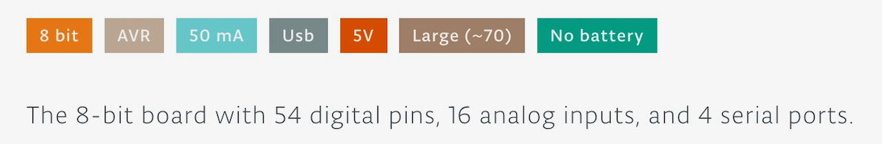
Arduino Mega
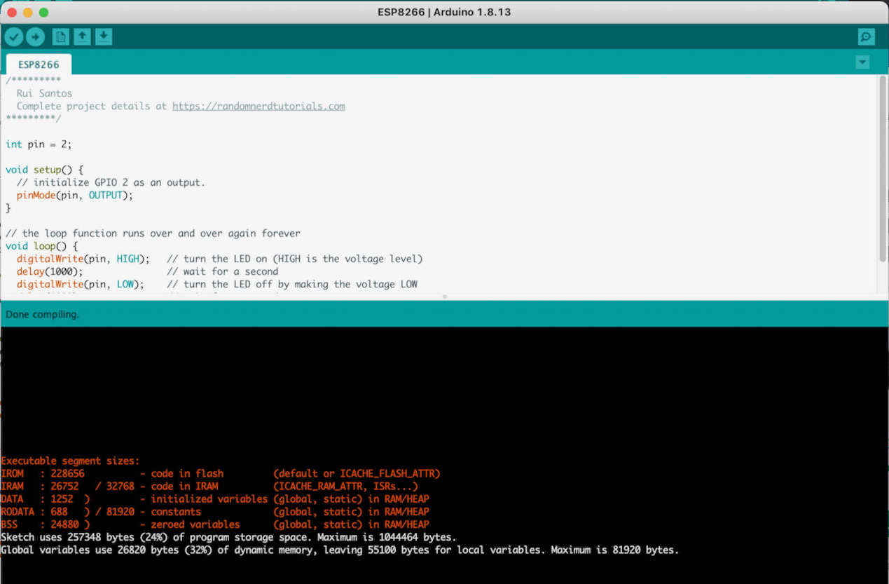
 We started with the biggest one with a simple USB serial connection. First of all we had to install Arduino IDE which was very easy and straight forward on this site. The good thing is that the board managers for the Arduino boards are already in their so basicly when installed we were ready to play. We used 2 examples that are on the tutorial site from Arduino, Blink and Fading which helped us to find our way through the programming.
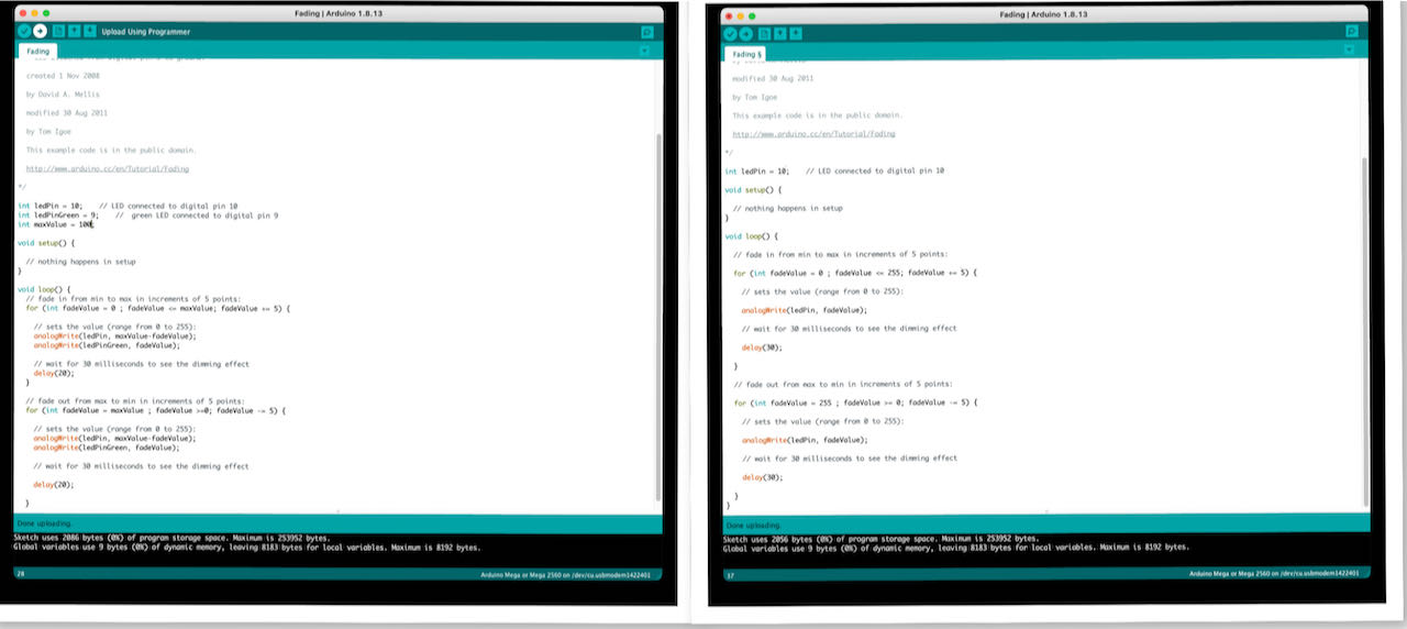
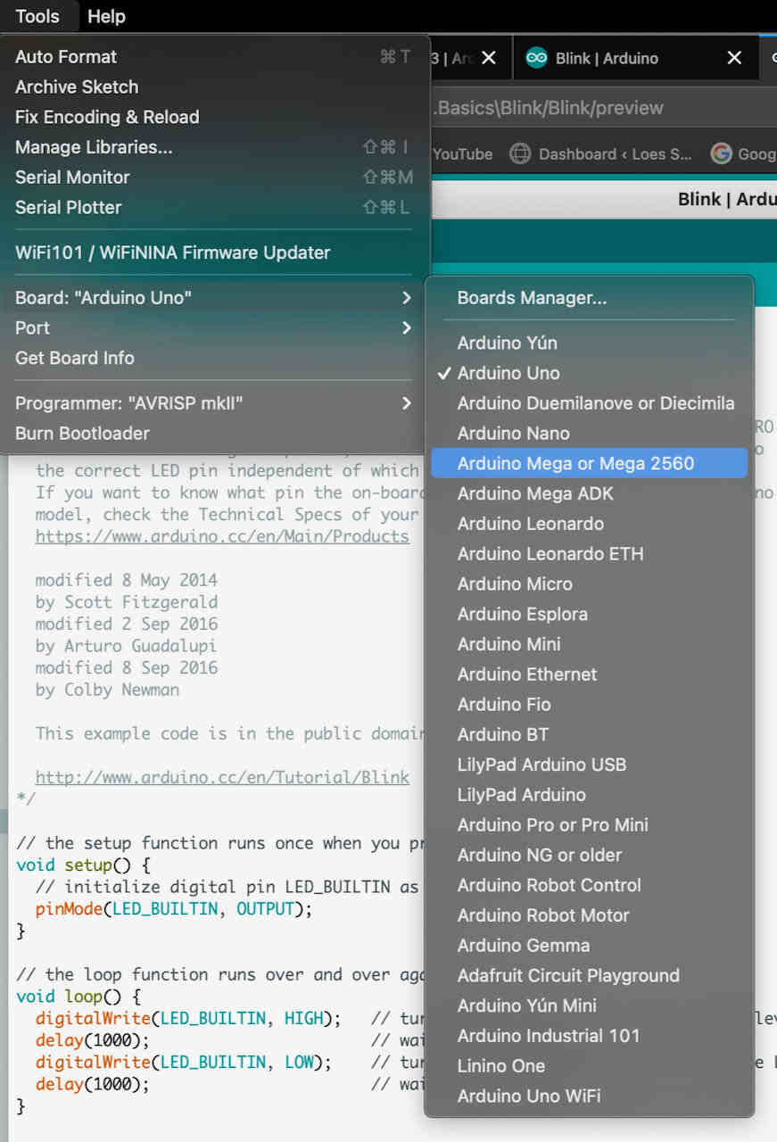
Then we had to select the right board and port under tools and we were ready to play.
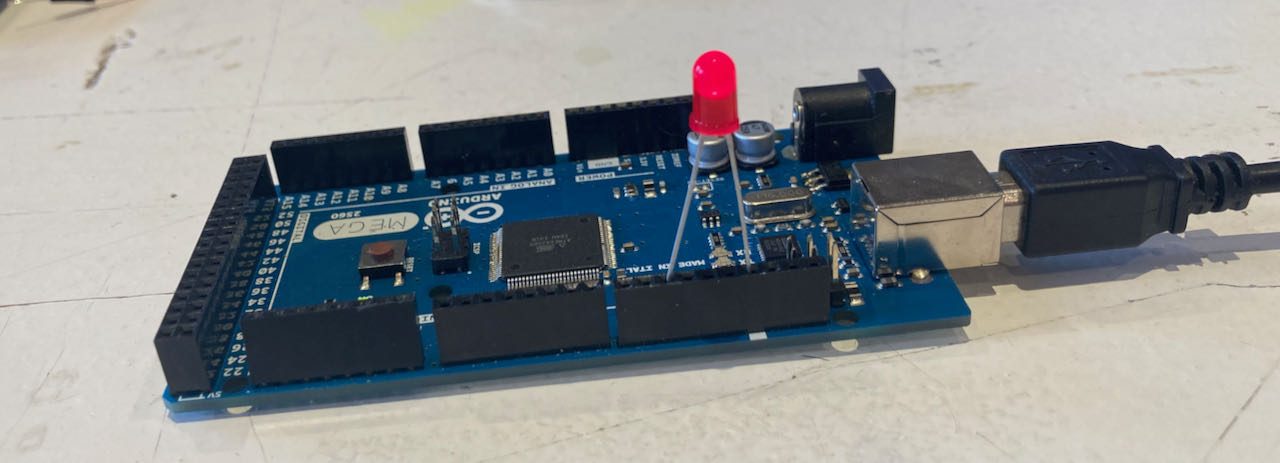
We started with one led on the Arduino board, was just a matter of finding the right pin that was specified in the program and connect the led to that one with the longest pin and the ground connected to the shortest.
After playing a bit around we tried to be a bit more adventures and start to connect through a breadboard which in the end is of course the same thing.
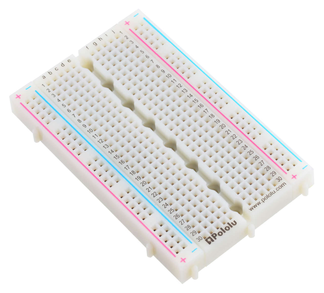
We understood how the holes were connected by googling the a fresh one that still has the print on it.
It splits in the middle + & - and separate + & - on both sides.
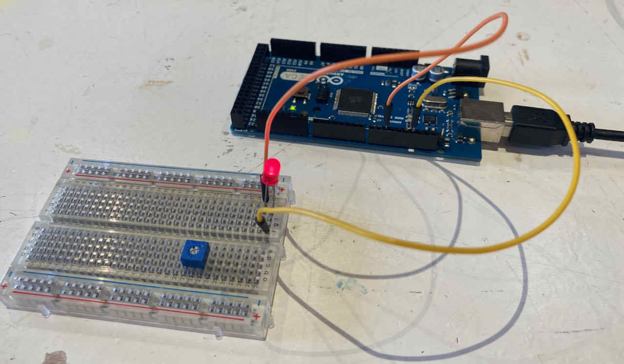
With some copy and pasting of the code we got to another led blinking.
Arduino Nano
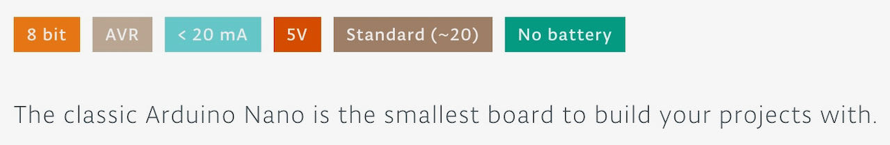
It took a bit of googling of images to realize this was the Nano and not the micro, also to realize that the connection is called a mini USB serial connection.
Use the old processor
WaagArduino
ESP8266
The ESP8266 is a low-cost Wi-Fi microchip, with a full TCP/IP stack and microcontroller capability with Micro USB serial connection.
This site helped us to figure out what we had to do to install ESP8266 in Arduino IDE.
When choosing the board we had to choose the NODEMCU board CP2102 1.0 driver not the 0.9 how we started.
We copied the code we used for the Arduino into a new file and changed the pin to 2.
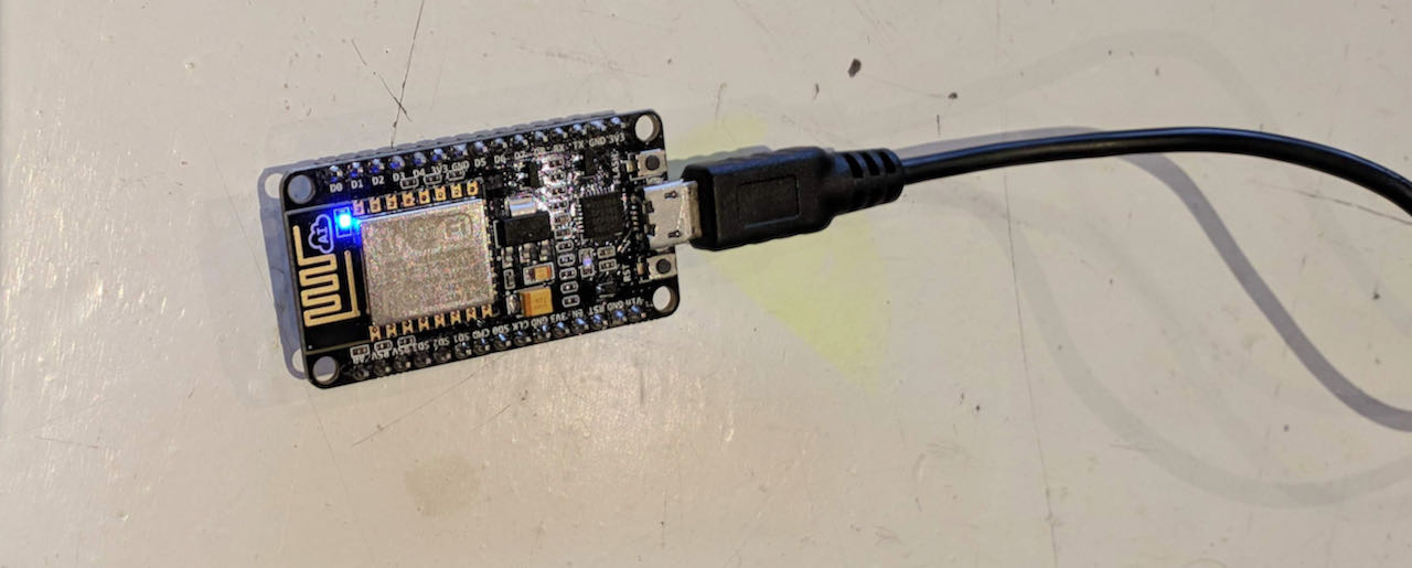
Connecting it to the breadboard was a challenge in itself keeping the pins connected. but it did give some freedom for which pins to use.
ESP32
ESP32 is a series of low-cost, low-power system on a chip micro controllers with integrated Wi-Fi and dual-mode Bluetooth. didn’t have time left to play with this one

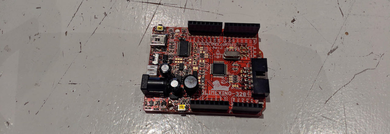
Olimex
Didn’t get a chance to play with this yet. But i have the board manager already for it in the ESPPackage i noticed while selecting the board for the ESP8266.
individual assignment
- Read the datasheet for the microcontroller you are programming. Program the board you have made to do something, with as many different programming languages and programming environments as possible.
- Program the board we made for week6 with Arduino IDE. Read or minimum go trough and understand the datasheet of the ATtiny412
- watch tutorials
- get an overview of programming
All the programming info for the ATtiny we found here on Spencer his Github site, very helpful.
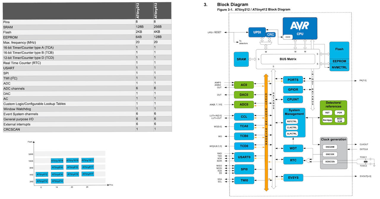
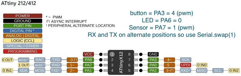
The 2 biggest differences in the ATtiny family is their memories and pins, found this little overview explaining it very well in the data sheet which thankfully is not that long, about 500 pages, so thankfull for the search function. On the right side its the internal mapping of the ATtiny, interesting to see and have an easy view of the possibilities.
Some compressed info:
- 8 pins
- 4 KB Flash Memory.
- 128 B EEPROM (electrically erasable programmable read-only memory)
- 256 B SRAM (static random-acces memory)
- Max frequency 20 MHz.
- Maximum voltage: 6V; minimum voltage -0.5 V.
Pins of the micro controller:
- VDD: Supply voltage.
- GND: Ground.
- Digital pins: PA0, PA1, PA2, PA3, PA4, PA5, PA6.
- Analog pins: PA1, PA2, PA3, PA4, PA5, PA6.
- UPDI Programming pin: PA0 (physical pin number 6).
- External Clock Pin: PA3.
Within the communications section there are different types and their pins are different. Different communication protocols cannot all be used at the same time, because they have pins in common.
- USART - Universal Synchronous and Asynchronous Receiver and Transmitter: It has the RX (PA1) and the TX (PA2).
- SPI - Serial Peripheral Interface: It has only MOSI (PA1), MISO (PA2) and SCK (PA3).
- TWI - Two Wire Interface (I2C): It has SDA (PA1) and SCL (PA2).
Another important thing that the data sheet is telling us is that you have to keep in mind which kind of input component you are using, digital or analog: for instance, if you are using a temperature sensor (analog component) you have to connect it to an ACD (analog to digital converter) port otherwise the micro controller isn’t able to transform the information that is receiving from the sensor to a digital data.
The information above is collected from the datasheet and several sites online in particular Adrian Torres his Fabsite has been very helpful for me to understand what i am doing.
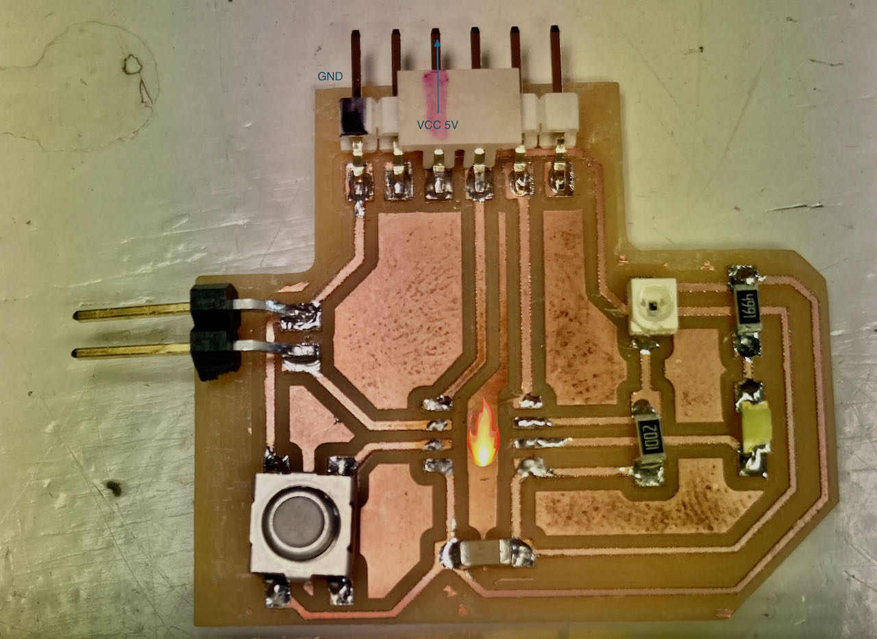
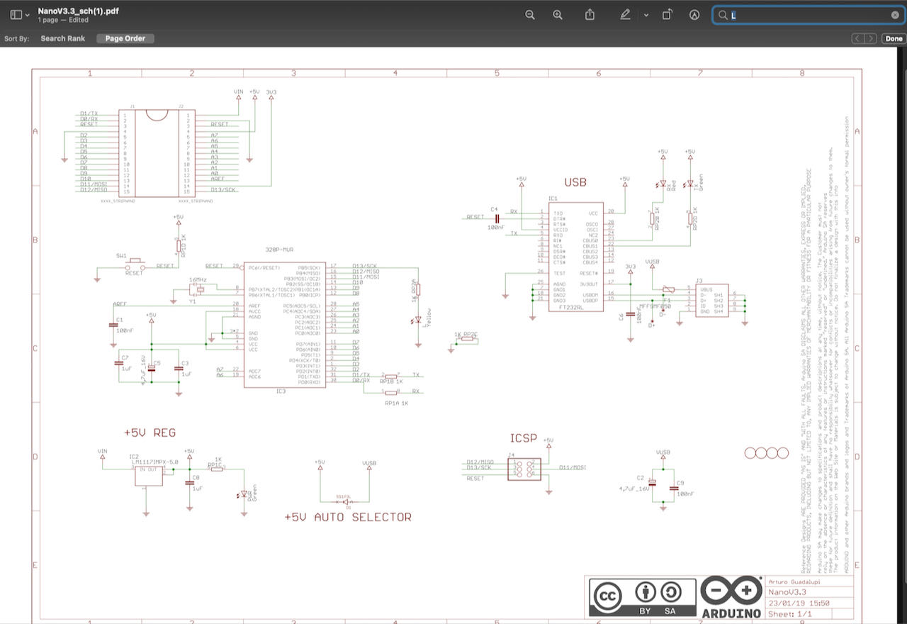
Below is the routing of our ATtiny412 as soldered on to the boards, with the RX on PA6 (pin4) and the TX on PA7 (pin5). But as you can read above the “normal” pins for RX is PA1 (pin11) and for the TX PA2 (pin12). More about this later.
Programming the board
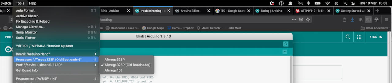
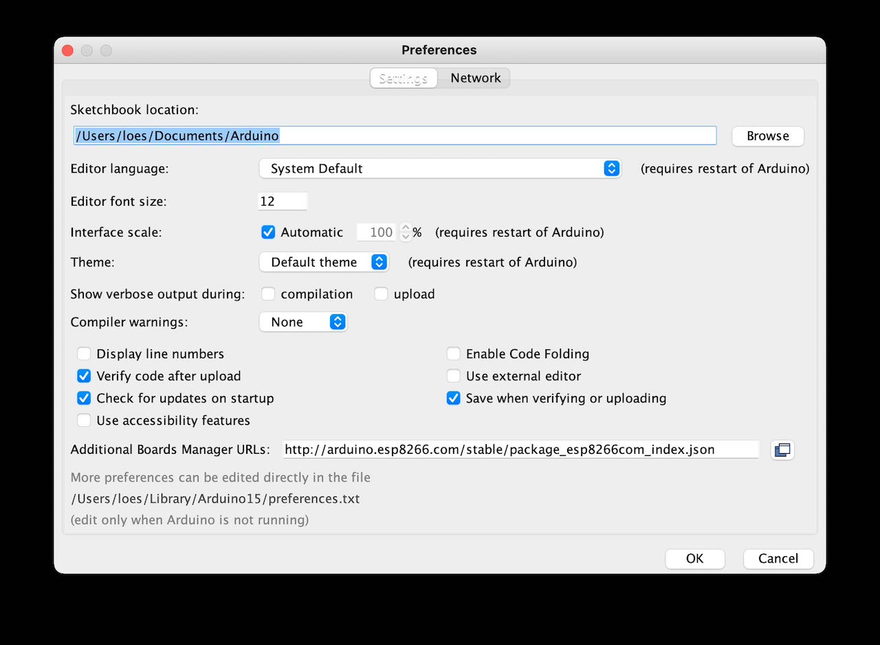
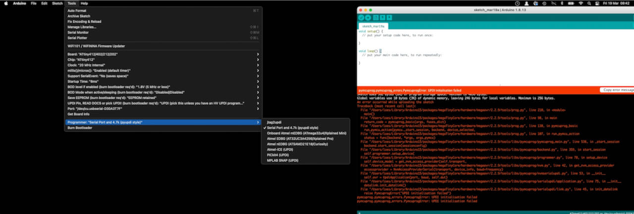
Back to Arduino IDE and how to program the board. Like with the ESP8266 we have to put a link of a board manager in the preferences, we uses megaTinyCore from Spencer Konde.
in tools:
- Board: ATtiny 412/402/212/202
- Clock: 20 mHz internal
- Port: /dev/tty.usbserial-D30A3T7F
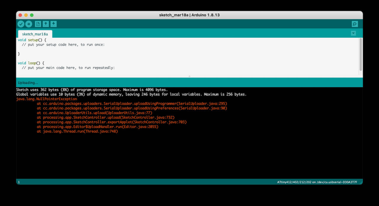
Now that everything seems to be working, i would connect my UPDI, FPDI and board but no luck.. so to avoid getting stuck into trying for to long we checked my boards (not a hundred procent sure if we also used my UPDI) on Nadieh her setup and it worked perfectly, able to program it in one go and here it is blinking it heart out.
Same board different MAC
Time to make it work on my computer..
Started with the obvious, deleted Arduino IDE of the computer also the hidden libraries remember to use cmd shift . to see the hidden files/folders, installed the nightly version of Arduino and also tried the beta version.
Whatever i tried this error kept on popping up, after 2 hours that gets a bit boring
Decided try the PYUPDI road first with the help of Nadieh and later with the video from Aalto lab, really helped.
On Github there is this repository from mraardvark with the Python UPDI driver for the new tiny AVR.
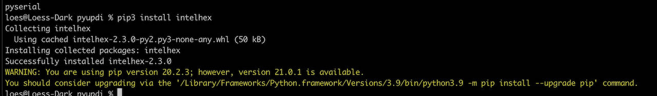
As mentioned i run in terminal pip install https://github.com/mraardvark/pyupdi/archive/master.zip
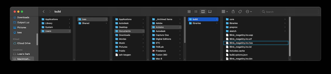
- via preferences in Arduino you can go to the preference.txt file, click on it
- close Arduino IDE
- add this short link of the buildpath.
in my case
build.path=Users/loes/Documents/Arduino/buildThe build folder i created manually in the already created Arduino folder.
- Open the Arduino IDE again
- Compose a program - not run it
- in the build folder you can now find a bunch of folder and also next to it your hex file
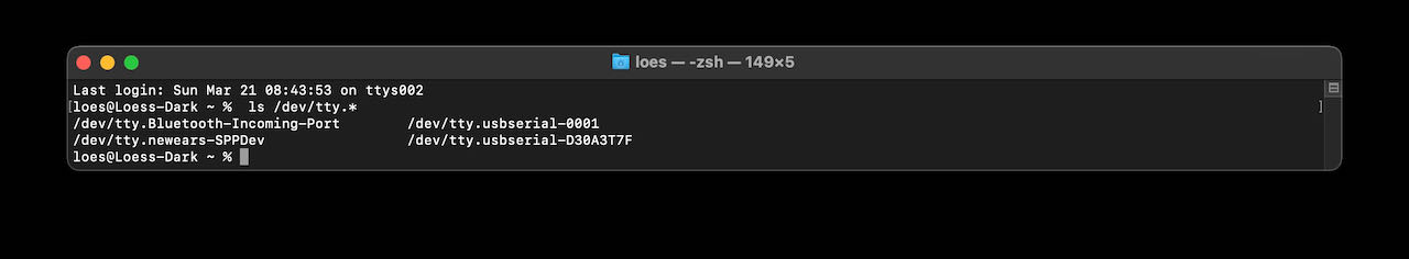
From Neil’s echo video we found that we need to fill this line:
python3 pyupdi.py -d your_processor -c your_port -b your_baud_rate -f your_hex_file -v
with my information:
python3 updi/pyupdi.py -d tiny412 -b 115200 -c /dev/tty.usbserial-D30A3T7F -f ~/Documents/Arduino/build/Blink_megatiny.ino.hex -v

Where to find this information:
The hex file you can find in the build folder you’ve created a few steps back.
The port you can find under tools/port in Arduino and also via terminal by running ls /dev/tty.* When in doubt which one just take it out run it again and see which one has disappeared.

Then Quentin replied as i was just packed to go home, he was able to help within 5 seconds by asking me what programming language we used… uhm.. oeps never did that so followed his tip after frying my microcontroller and or resistor by reversing GND and VCC in my rush to get it to work and go home, luckily it seems like the ATtiny survived.
@home
Then it was time to continue the search at home.
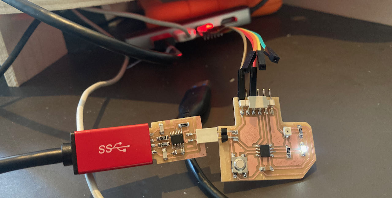
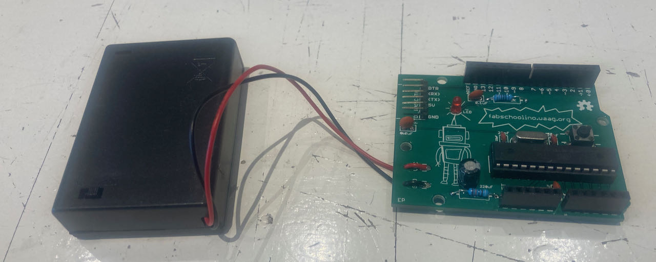
It started out hopeful, when the board was connected to the power via de FPDI which i borrowed from the Waag the LED started to burn on a low intensity, only when the button is pressed and hold for 1 sec the blinking starts.
 Luckily i was able to borrow the FPDI from the Waag to continue the search.
Following Aalto Fablab their class i realized i have an “old” pip version so that was easily fixed with the command suggest by terminal.
When following the steps i came to the point where the FYUPDI.py should have been created by pip3 install -r requirements.txt
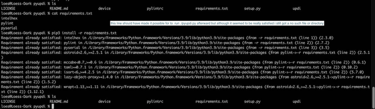
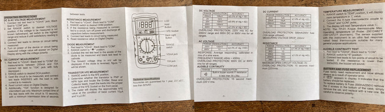
That’s when i got stuck on that road. Decided to give the good old multimeter a try to see if maybe my UPDI is simply not working. Luckily enough i just got a new one with the electronics kit so could give it it’s first test run.
If my fingers are stable enough i think that the RX and the GND are connected, not a 100% sure they are so close together.
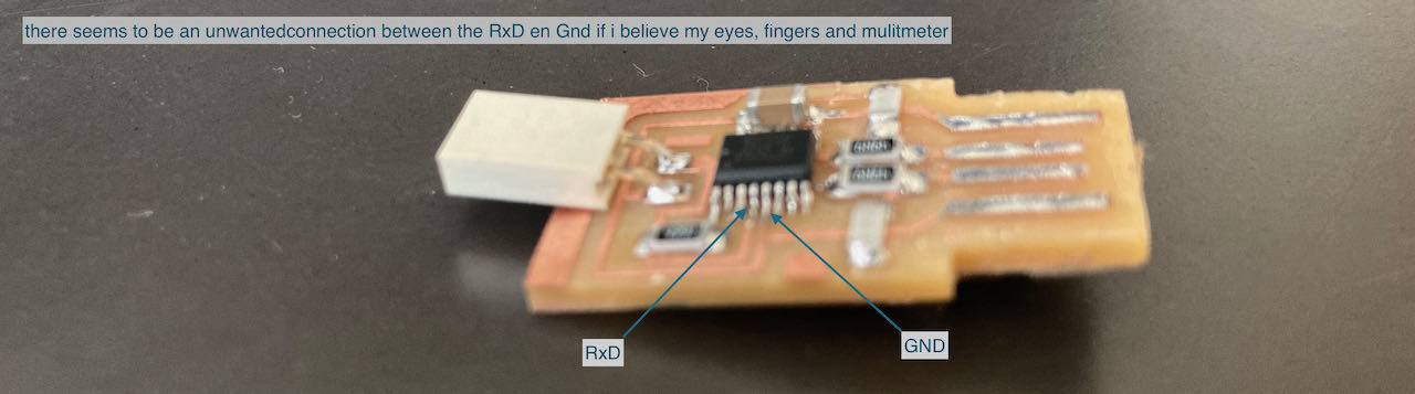
Checked this back at the Waag and realized that my UPDI is fine by putting in into a working setup.
Nadieh found out and shared with us that Henk used the alternative positions for the RX and TX, which is documented in the datasheet. Make sure you look at the right datasheet, there are 2 of them out there. This is the correct datasheet
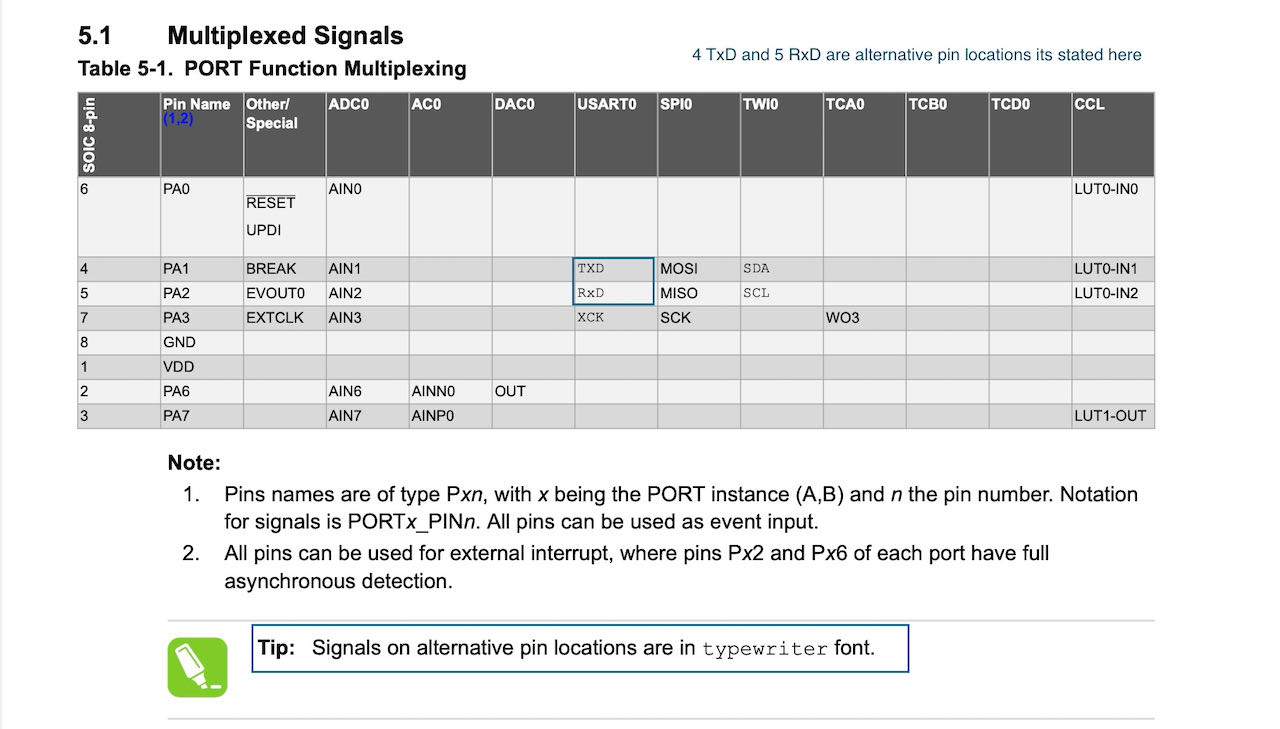
To switch to the alternative RX en TX use this code in your program
Serial.Swap(1);
when programming the button i should use
pinMode(button_pin, INPUT_PULLUP)
- instead of
pinMode(button_pin, INPUT)
This is all for future use when i actually can make my board work.
Back at the Waag i found out that my set gives the same error messages on different computers/setups, from Henks Linux laptop to the Mac with the FPDI in a separate USB power as Adrian suggested on the global time.
So back to the soldering board
- first put a new ATtiny on there since i deepfried the old one, no succces i thought, exactly the same error
- replacing the Capacitor 1uf for a new one, also no luck
With a magnifiar Henk noticed that one of the pins from the ATtiny was not connected properly and after soldering he checked it for me with a multimeter.
I connected it back to my computer and no luck.. Henk checked it on his linux and for whatever reason it worked…
Looking back now that i am in Week 16 i realise i used the wrong pins because i based it on the pinout of the 1614, that shows how little i understood back then.
Here is the right pinout:
I ended up trying to make the LED fade with this code:
// Using "software PWM" to fade my LED
// Loosely based on: https://forum.arduino.cc/index.php?topic=104572.0

const int led_pin = 0;
float steps = 25; // The max time of each step
float fade_step = 0.2;
// It takes (steps / fade_step) steps to go from OFF to ON
// the "delay()" function should take "unsigned long"
// but I really need 0.5 milliseconds or less
// and using the delayMicroSeconds() doesn't work,
// because it can't handle numbers above a few thousand microseconds
// which is only a few milliseconds

void setup() {
  Serial.swap(1); //Because I have swapped TX/RX pins
  pinMode(led_pin, OUTPUT);
}//void setup

void loop(){
  // Fade to bright | Runs from 0% -> 100%
  for(float i = 0; i <= steps; i += fade_step) {
    digitalWrite(led_pin, HIGH);
    delay(i);         // ON for this long
    digitalWrite(led_pin, LOW);
    delay(steps - i); // OFF for this long, the remaining "pulse width"
  }//for

  // Stay on for a while
  digitalWrite(led_pin, HIGH);
  delay(100);

  // Fade to dim | Runs from 100% -> 0%
  for(float i = steps; i >= 0; i -= fade_step){
    digitalWrite(led_pin, HIGH);
    delay(i);
    digitalWrite(led_pin, LOW);
    delay(steps - i);
  }//for

  // Stay off for a while
  digitalWrite(led_pin, LOW);
  delay(100);
}//void loop
Which looked like this:
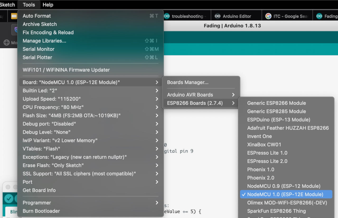
Plan B - trying to programme an ESP32 AZ Delivery
Google helped me to find this random nerd tutorial
- in preferences in the additional board mangager URL paste this
https://dl.espressif.com/dl/package_esp32_index.json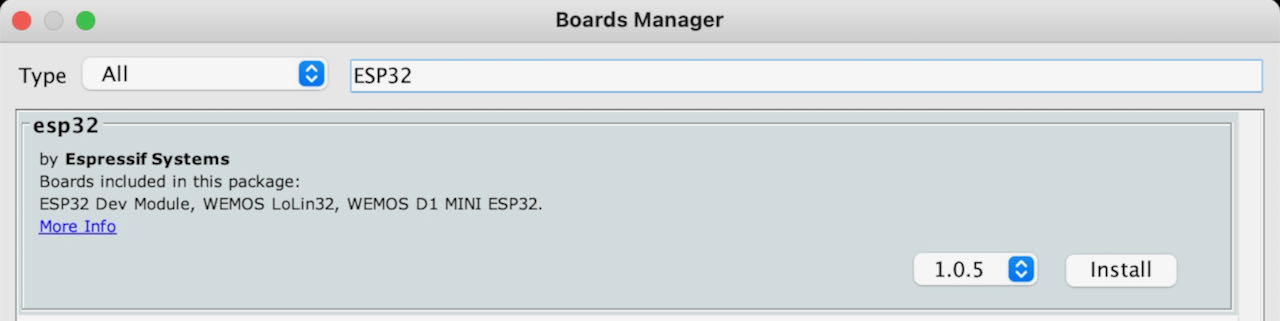
- select the DOIT ESPuino32
- Port
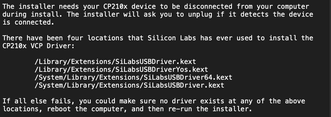
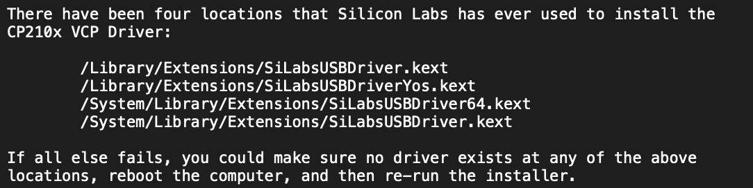
comdidn’t show up so i had to install missing drivers from here (CP210x USB to UART Bridge VCP Drivers)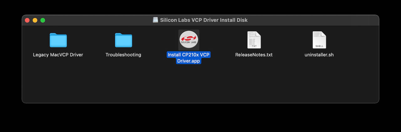 At first it didn’t show up so read the Troubleshooting folder and followed their suggested steps.
Checked with terminal to see if it was showing up there at least but nope.

Rebooted the computer and reinstalled the driver, so far no luck, think i call it a (sun)day
Handy trouble shootingsite for the ESP32 you can find here Hoping that its my micro USB.. could be only a changer cable, don’t remember where i got it from.
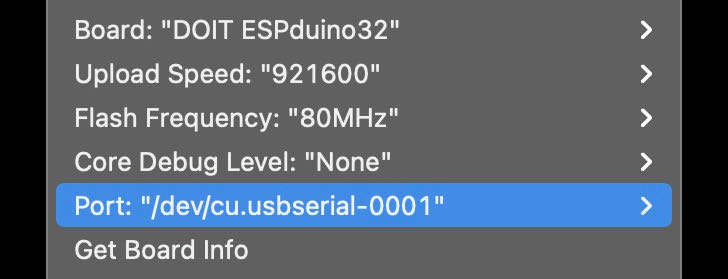
YES! port exists! the cable swap was the first step, now time to get rid of the same old javabug again.
Decided to just select another board since it seems very specific although it was the one that the random nerd site suggested. Thought i would not hurt so selected the general ESP32DEV module.. eh voila working.
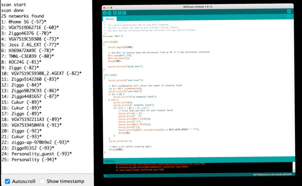
From the examples i opened the wifiscan, uploaded it and opened the serial monitor shift cmd M to look at the proces.
Now that i am on it i also wanted the led to blink, in this case the led is on pin1, used the file from the ESP6288 and just changed the pin number and magicly it worked in one go.
OK got it working with the Arduino IDE.. what else can i do..?
Created/copied a nice LED base to work with some extra leds ones i have a set up for this, maybe i can borrow or buy a breadboard?
MicroPyton
On to MicroPython with help from this tutorial
MicroPython is designed to work under constrained conditions, so it doesn’t have the full library only a small subset of the Pyton standard library. It’s easy to learn and seems to be a good starting point.
uPyCraft
The software to use is called uPyCraft, so lets install some software again with a bit of help this time from this site
Installing uPyCraft IDE
- check the P{ython version, which i know, Pyton 3.9
- download the IDE here
- in my case it asked for some fonts to download
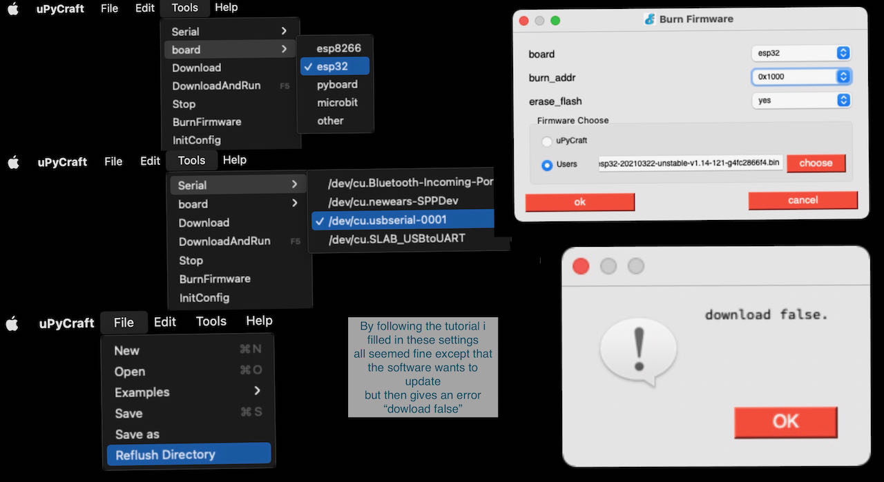
downloading the firmware
on this randomnerdsite you find the steps to follow.
- download the firmware on this MicroPytonSite
- go to the MicroPython Downloads page and scroll all the way down to the ESP32 section.
- the latest link to download the ESP32 .bin file – in my case: esp32-20210322-unstable-v1.14-121-g4fc2866f4.bin
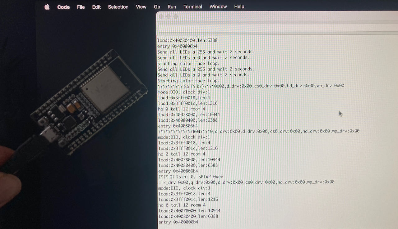
After following all the steps the software was trying to update and was not able to or at least it mentioned that the download was false.
It seemed to still work so i tried to continue with some programming:
Binking an LED is as simple as follows:
from machine import Pin
from time import sleep

led = Pin(2, Pin.OUT)

while True:
  led.value(not led.value())
  sleep(0.5)
but when i tried to copy this in my editor i got this:
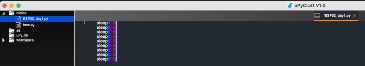
After a bit of googling i found out that i could be missing a SourceCodeFont which i found here Downloaded it and installed it. Still the same missing text..
PYmakr
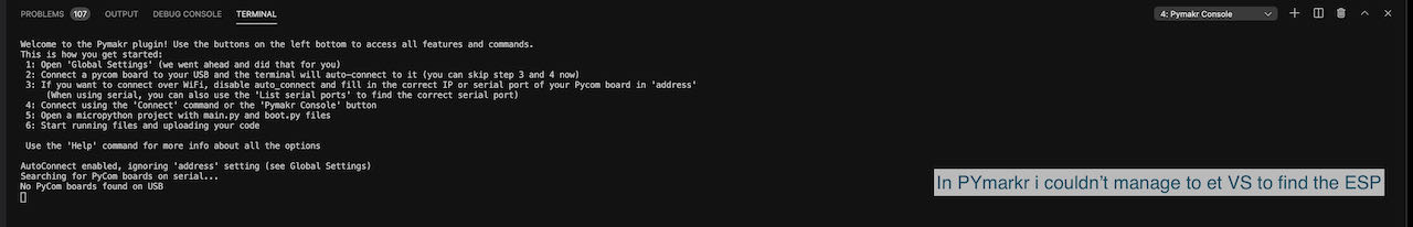
Decided to see if i can make MicroPython work in Visual Code, this would at least safe me another program to install.
Found Pymakr extension via this link Still had to install a JavaScript runtime NodeJS
Did this all but very soon got back into weird errors and not being able to google the right things to make it work.
Later on i realized thanks to the googling of Nadieh that our ATtiny have only 4KB of Flash and 256B of SRAM which is not sufficient to use MicroPython since it says on their website they need 56k of code space and 16k of RAM to be able to run.
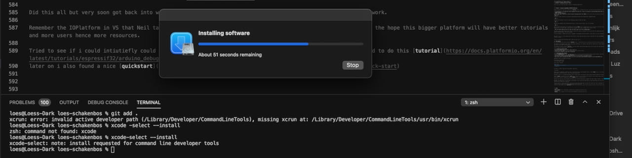
Remember the IOPlatform in VS that Neil talked about in his lecture and went back to the drawing board but with the hope this bigger platform will have better tutorials and more users hence more resources.
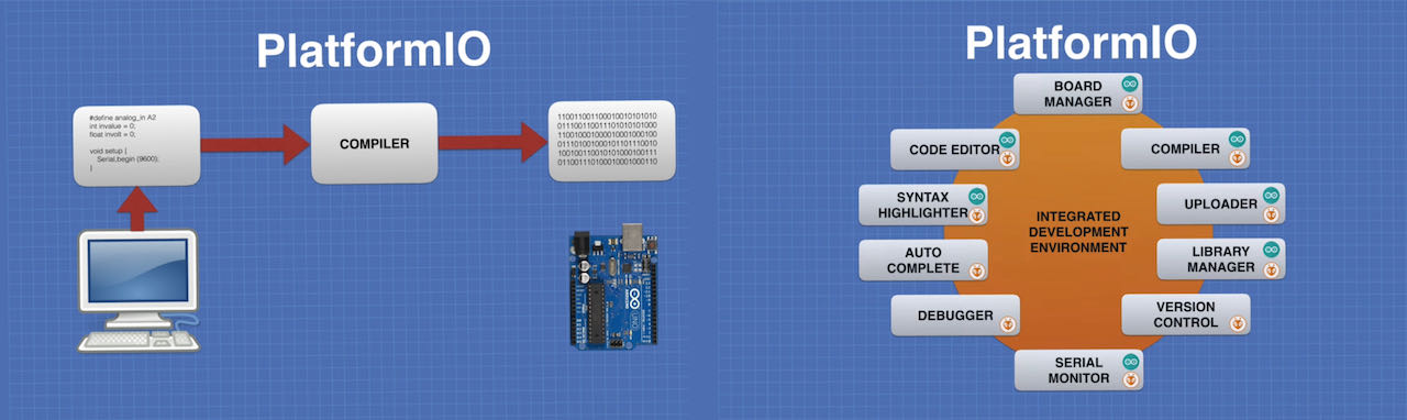
Platform IO
- Platform IO is pure Python and doesn’t depend on any aditional libraries or tools and you can use it on any platform which makes it very broadly used.
- Integrated Debugger (comprehensive debugging with extensive support for debugging probes and terget systems)
- Unit Testing (a common testing enviroment for multiple projects with different platforms)
- Static Code Analysis (detect the precise location of potentiaal defects)
- Remote Development (program devices using Cloud IDE)
to find the Platform IO home jsut go to the blue part below and press home

All the little icons down there are very handy, for instance the little plug opens the connections where you can easlily type in a number and see whats connected.
Tried to see if i could intiutiefly could find my way around (bad idea) but got into a mess very fast so decided to do this tutorial later on i also found a nice quickstart
Working with the Platform IO seems very similar to Arduino, looks a bit different but the basics are the same. one important difference is that the programming is more like normal programming, like the order is important, functions at the beginning, which is problaly good for me to be working with so i learn how to program in an organized way.
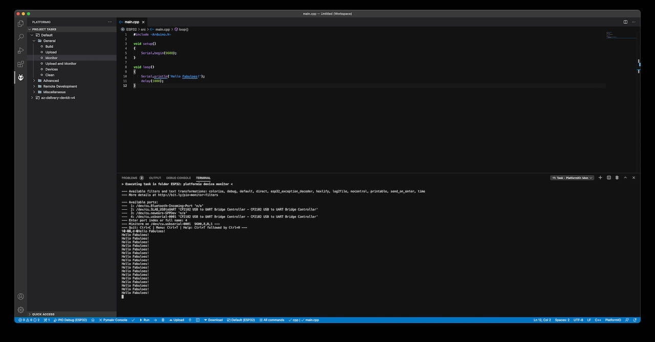
Made a simple Hello program and a blinking led to get an idea of the program.
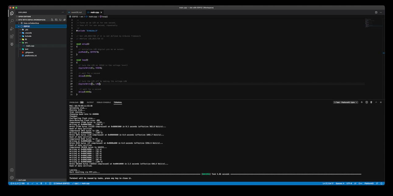
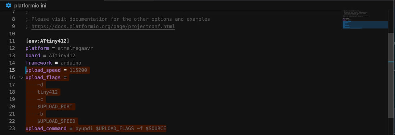
For a strange reason when i wanted to program my “own” ATtiny412 i had to add some lines into the platform.ini file if i understand correctly because we use pyupdi to program.. need to dig into this a bit more.
Not sure which road to follow but with the ATtiny it seems much easier to program via the Arduino IDE Found a nice Tachometer Tutorial set up which would be cool to try once.
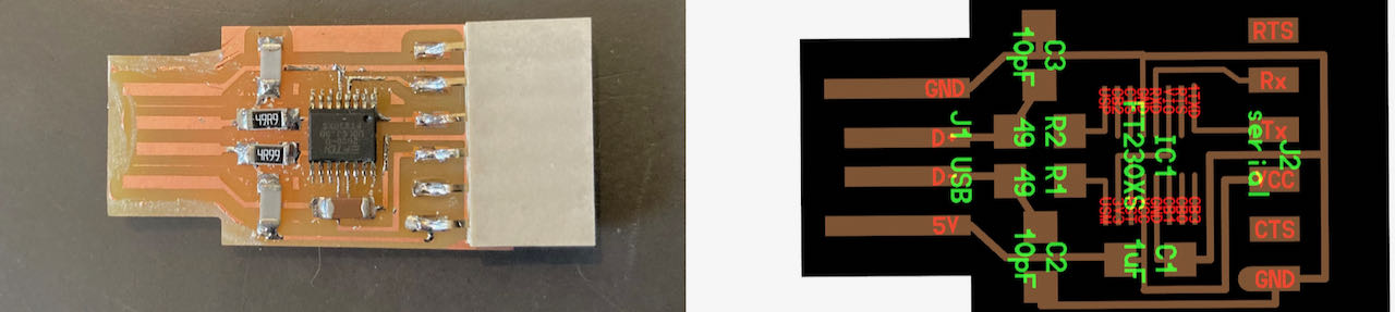
Decided to make a FPDI for myself so i am not able to swap the GND and VCC again, luckily no given directions in this board :)
| Components | amount |
|---|---|
| Capacitator 1uF | 1x |
| Capacitator 10pF | 2x |
| Resistor 4.99 | 2x |
| Serial connector | 1x |
| IC1 FT230XS | 1x |
Git
Same as with the last update from OS i had to download a new version of Xcode, getting used to it.
- got very frustrated with getting stuck on places like not knowing that i should choose a language in Arduino IDE instead of learning which language to choose or how to program.
 - work more spirally, first check the board and make sure you have all the pins information before doing anything else. Next time i should watch a tutorial before the class at the waag so i can actually learn something instead of just hearing words without knowing what they mean.
- look more into programming, maybe for next week i should try to be the one to program, gives me another week to learn.