My project Assigment
For this week assigment, me and Mathieu decided to make a smart zen garde, to do so, Mathieu design a case that would fit the MTM kit that we bought, we followed the instruction to assemble the MTM here and
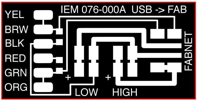
The first part of my assigment was to produce the necessary PCB for our machine to work. In our case, this only meant I had to do the FabNet. The FabNet is a really simple electronic design that serve as a multi-drop network. It's also providing power to the motors and the gestalts nodes.
Like I said the board is a simple design and only need a handfull of component and material to produce, these are all extremely comon and can be find in the fabacademy inventory. Here is the BOM:
- FTDI Cable
12-24V Power Supply (amp depends on the motors you use, I recommend at least 4A)
-2x 590 Ohms Resistors
-4 pin male headers
- 6 pin male headers
That's it!
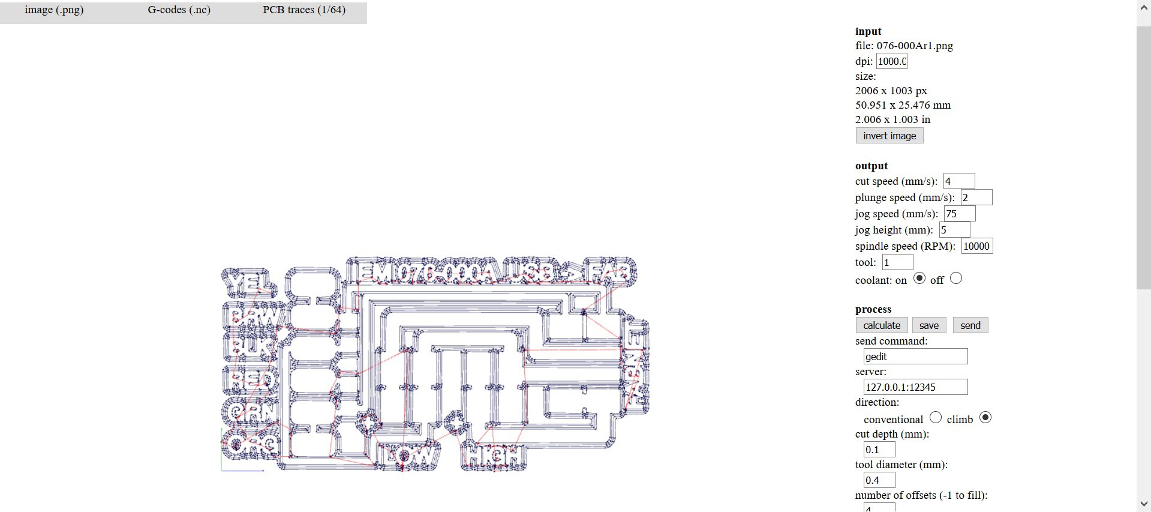
Once I had everything, I milled the board using my newly acquired CNC at my house! I went and take the png file I found on the FabNet official website and did the same routine as always, using the fabmodules I create two Gcode, one for my PCB trace using a 1/64" mill and an other one for my outline using a 1/32" mill.
Soldering the board was a small and easy job since all I had to solder was a couple of wire, two resistance and some headers. here are the final results:
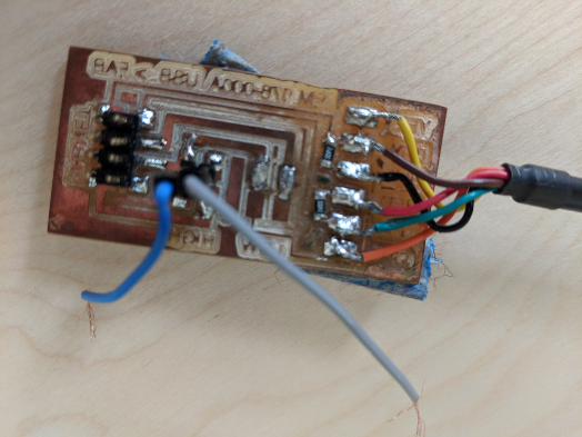
One thing I found is that the FabNet usually use two voltage supply, one at a high voltage (12-24v) that serves to power the motors and an other low voltage that is supposed to serve as a power source for the logic circuits of the nodes. I found that I didn't really need the low voltage power supply and could ignore it and power up my motors and my nodes on the same high power supply. Thats what I did.
First thing I did before trying to program my gestalt node was to read about them. I wanted to fully comprehend what they were, what was their purpose and what was inside them. I never worked with motor driver before and I was far from comfortable with my assigment.
I found that the gestalt nodes were a kind of driver motor that use high level programming languages such as python to controlled tool instead of the decades-old G-code standard. It was developped to automated machines via commonly aviable interface such as USB virtual ports. The Gestalt use a virtual machine to control a real machine. The virtual machine is computer-based that runs on the user's computer. Information such as machine configuration and state is stored into the virtual machine. We the work with two kind of nodes, the first one being the "virtual node" and the other one being the "physical node". The physical node talk in the language of gestalt and it's firmware do all the time-sensitive calculations,like when to take a step. The virtual node in the other end, can be programmed in programming languages such as python and is used to write complex firmware that will be read directly on the computer istead of inside a microcontroller like a typical motor driver.
This is a brief explanation of what I understand (please be aware that it is only MY comprehension of the concept)of what a gestalt nodes do, it basicly consist in a hardware/software interface that give you the possibility to write software and run it from inside your computer while the machine controller (physical node) talks to the actual hardware such as stepper and automated your machine.
For a more in Deph explanation of what are the Gestalt node please refer to the documentation I found here
Ok! all of this still seem a bit overwhelming, so let's look at a actual gestalt, what it looked like, what's it's pinout.
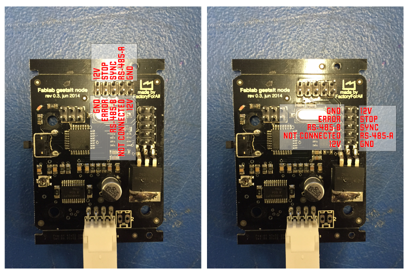
We can see here that the Gestalt pocess a connector for the motor, a 6 header pinout that strangly look like a ISP, and two 10 header pinout that have the purpose of allimenting the necessary voltage to the board and the motors and to transfer data to the motors. but why two? Well this is what we call a daisy chain, a daisy chain is a wiring scheme in wich multiple device are wired together in sequence. Daisy chain are used for power, analog signals and/or digital data communication. more info about daisy chaining here .
So you guessed it, we will use one gestalt per motor we will be using, there will be a master gestalt and then every next gestalt will be daisy chain to the one before. we can see it in this schematic:
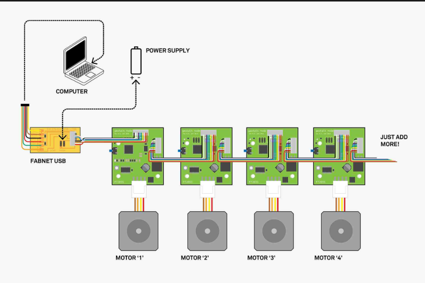
On the 10 pin header, we will only use the 12V pins, the ground pins, and the RS-485-A and -B pins. The other ones seems useless for me.
So we now know how to connect our Fabnet to our Gestalt and ou motors to our Gestalts. Let's make it happen!
*One thing to remember is that you MUST never connect the power supply before anything else, the power is the last thing you want to turn on!
Now that we have a Gestalt wired, let's try to send some code to it. For that, there is a few steps we need to do. first we need to download the pygestalt librairie that you can find on the nadya peek github. Once this is acquired, you need to install the FTDI Drivers so you can communicate with your serial FTDI cable. This shoud already have been done in the embedded programming week, but who knows..
You'l also need a IDE to work with the code, since it"s python, I suggest Pycharm wich is a great IDE, but I will use VIM wich is a smart text editor that operate directly trought the linux terminal. I will use VIM since I really want to familiarize myself with its interface.
First thing I done is open and look at Nadya Peek example code: single_node.py
If we look at the code, we will see that the library required to run the code, then we can see the virtual machine I was talking about earlier.
I won't go trouph every single line of the code, but some are pretty interesting, first of all let's look at this one:
def initInterfaces(self):
																	else: self.fabnet = interfaces.gestaltInterface('FABNET', interfaces.serialInterface(baudRate = 115200, interfaceType = 'ftdi', portName = '/dev/ttyUSB0'))
We can read here that it is the place where we define which kind of serial read interface we will be using to communicate data (ftdi) and at wich baudrate we will sent those data (115200). Also, the last information can change depending on your computer, the portName is subject to variation depending on the hardware.
The lines that have a # before them are comment-out, this mean that we may want to use them for some purposes, but they are not part of the base code. Next we have all kind of information like the definition of our axis (only one for this example) and the measure system we are using in our array of coordinate (mm).
def initControllers(self):
																	self.xAxisNode = nodes.networkedGestaltNode('X Axis', self.fabnet, filename = '086-005a.py', persistence = self.persistence)
																	self.xNode = nodes.compoundNode(self.xAxisNode)
def initCoordinates(self)
																	self.position = state.coordinate(['mm'])
It is always interesting to see what we can find in a code that you didn't wrote yourself, I am still really new to the programming world, and I learn a lot just by peeking other people code. Once thing I see from Nadya code is that the Gestalt seem really modular and we can do pretty much what we want with them, it really seems like a nice and simple interface.
We can also see in the code this line:
supercoords = [[10],[20],[10],[0]]
This is an array, and it's our coordinate, for now we only have one number per movment since we only move our X axis, but I will use this syntax of array to draw my svg so now I know how I want to parse my files.
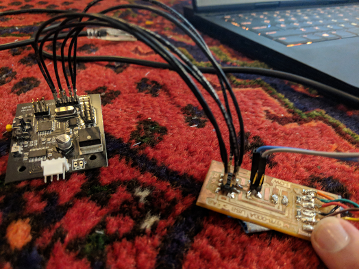
Ok enouph talk, let's test things! All I need to do is to wired my gestalt and fabnet, plug it into the computer and run the code, I will first have to connect my node to an axis.
Once my node is sync with my x axis I can start over a look at the results:
v
It works! Now let's try with the xy_plotter.py code. I just need to daisy chain another Gestalt and plug another motor. For test purpose I use a switching power supply, set it to 12volt and jack up the current to be sure I have enouph, Each Gestalt can take up to 2 Amps, I test using a multimeter, my gestalt nodes use 0.25 A each and my motor on full drive use 1.7 A.
Ok this part was frustrading, I tough I was busting my Gestalt due to some kind of current overload when I was switching my power supply on or whatever, the daisy chain also seemed part of the problem since the first Gestalt was always good, but the second one was not responsive. Sometime not at all, sometime acting crazy. I troubleshoot for several hours, tried with different Gestalt, nothing seems to work...Finally, I realised that I was using BROKEN jumper!!! Always check your jumper before using them for testing purposes, that's what I learn!
I have no images of the result while the issues was happening, late at night, no more battery on my cellphone... the important is that you remember, CHECK YOUR JUMPER.
Let's try again with working jumpers!
It works!!
here is the machine in action, the magnet need a bit more force to drive the ball correctly, the ball keep losing it's track, so yes, we still need a bit of tweaking on the machine, but I think it starting to look really great!
Here is a link to my partner Mathieu project page
Also, here is our project page for the group assigment.
You will find the rest of the documentation of the project there.