Week 10: Input devices
This week we followed the Input Devices class (see video here)
- Input test board
- Temperature device
- Magnetic sensor device
- Reading analog values with Arduino
- Accelerometer sensor device
- Heartrate sensor device
- Lessons learned
- Next steps
For this week asssignment I decided to explore different sensors and to build a basic board to which I could connect the sensors. I’m going to build a simple sensor and then explore few more sensor that I’m curious about.
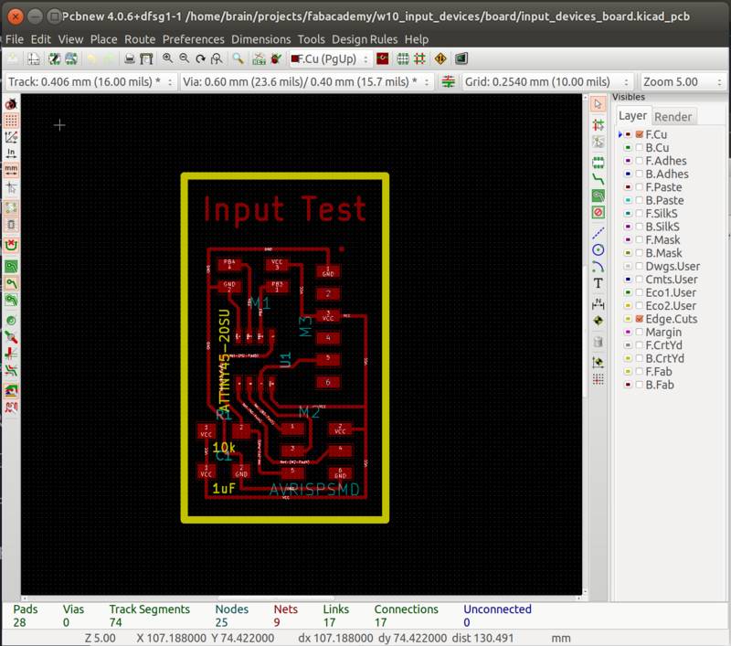
The production process for all the boards described below followed the same processes documented in week 6 (design with KiCAD, .png conversions, using mods) and week 4 (electronics production, milling PCB and soldering)
Input test board
The idea is that I can create the “Input Test” board with a small header using the ATiny45 PB3 and PB4 pins, VCC and GND. This combination of pins allows in the future to combine different sensors on the same test board.
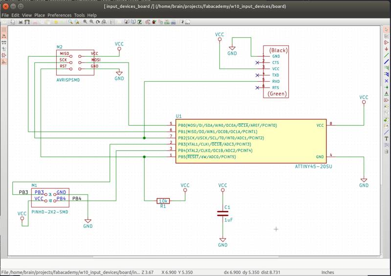
From the FTDI bus header I connected only the VCC, GND and RX pin so that I could debug and send data to my laptop and leave enough pins of the ATTiny45 available.
Looking at the design you can see that the custom header makes PB3 and PB4 available.
These pins are very flexible because allow to do analog reading and A/D conversions, but can also be used in “digital” mode for example as pins of a I2C bus.
Finally the board has a capacitor to stabilize VCC-GND and a pullup resistor for the RESET programming pin on the ISP bus.
With the above characteristics this board can be used in many conditions where an ATTiny45 is sufficient.
Download KiCAD project and GCode (.zip archive: KiCAD project, .png and .rml files)
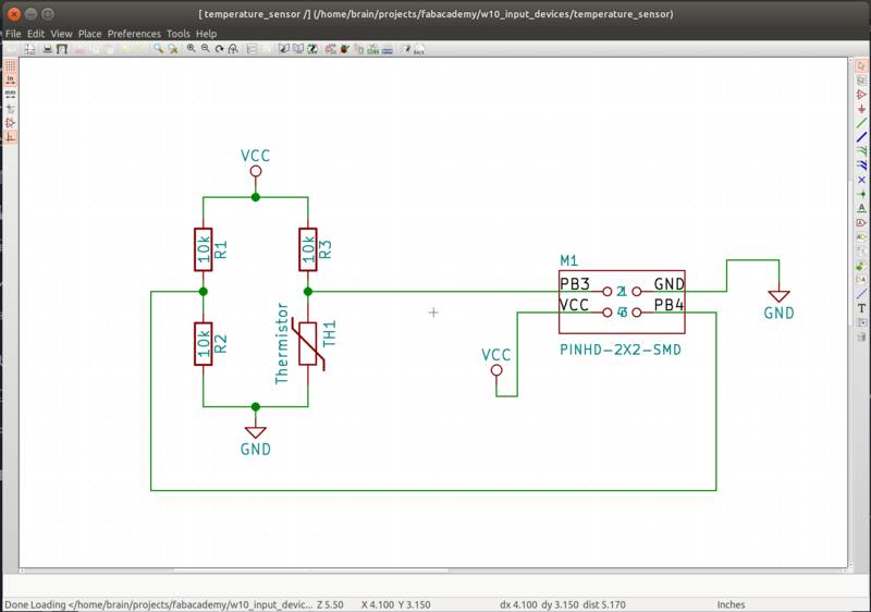
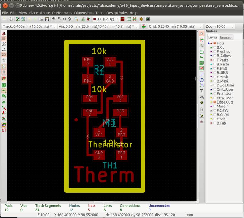
Temperature device
Similar to Neil’s example for the temperature device we are going to put the thermistor component in a bridge configuration. With the two available ATtiny pins we will measure the difference between the two sided of the bridge. You can find a good documentation of the bridge configuration in this page
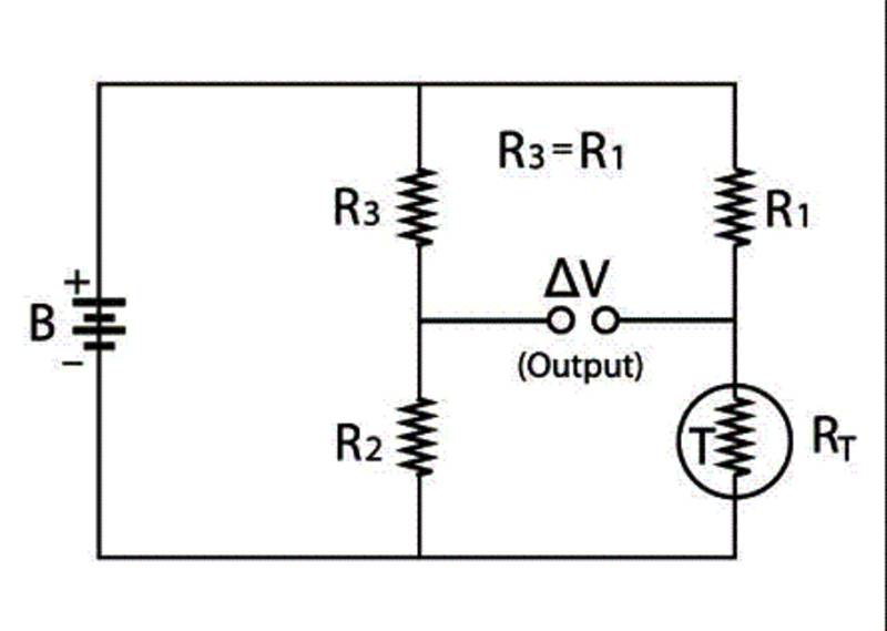 Image from ametherm
The main advantage of a bridge is that at equilibrium condition the meter does not absorb power from the circuit making it more accurate.
The disadvantage is that the relationship between Temperature and Voltage become non-linear, but for small T ranges a linear approximation can be still valid.
Download KiCAD project and GCode (.zip archive: KiCAD project, .png and .rml files)
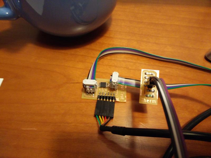
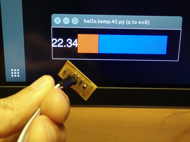
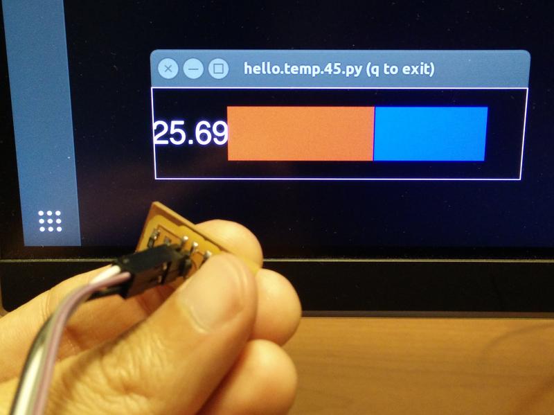
The working temperature sensor
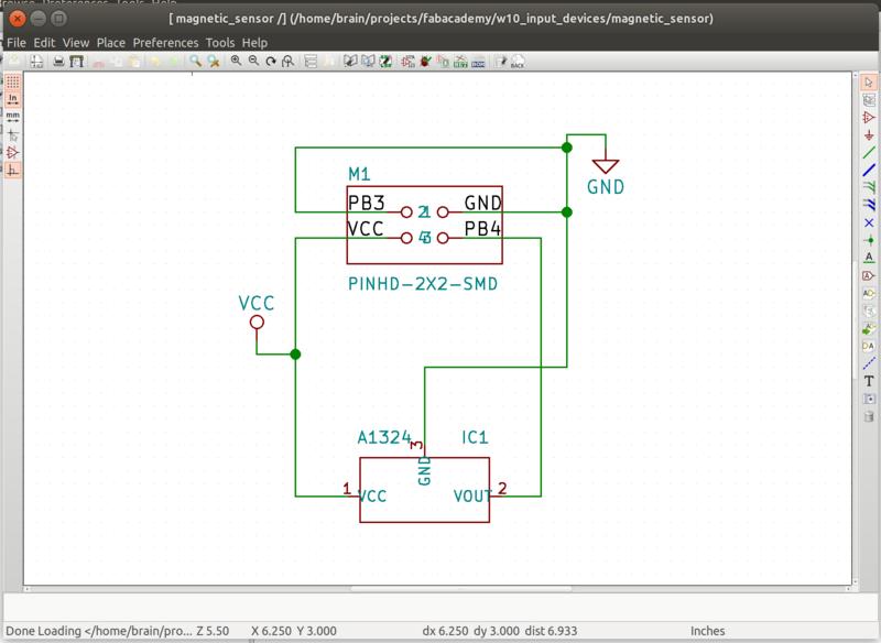
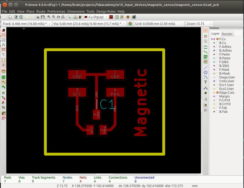
Magnetic sensor device
Another simple sensor that can be directly connected to the analog pin is a hall effect magnetic sensor.
Download KiCAD project and GCode (.zip archive: KiCAD project, .png and .rml files)
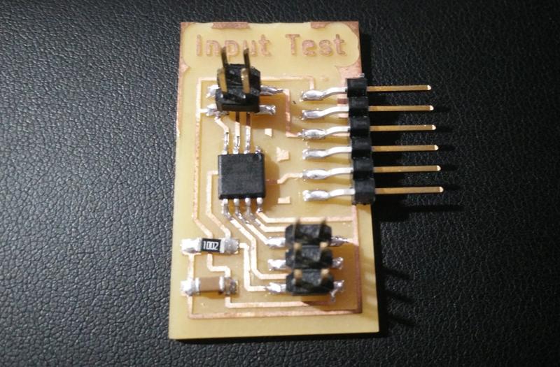
Here are all the 3 stuffed boards:
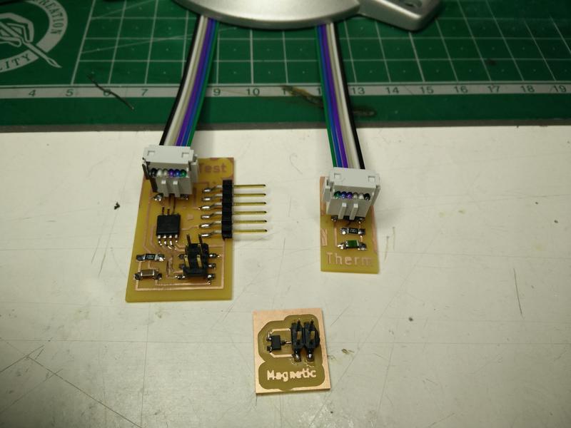
The working magnetic sensor
Reading analog values with Arduino
The video below shows the simplicity of using the Arduino IDE and libraries, an Arduino UNO board with breadboard to read a simple analog value of a photoresistor.
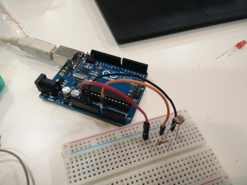
Learning to use Arduino makes accessible a quick and easy to use tool. This is useful in the experimental phases of a product where quicker iterations are needed.
Accelerometer sensor device
Finally I decided to try a more complex sensor that could help me preparing for the final project the ADXL343 acceleromenter.
The sensor that we are going to use, similarly to the heartbeat sensor, has an interface with I2C protocol and a very small footprint and small pin pitch that will require a different soldering tecnique.
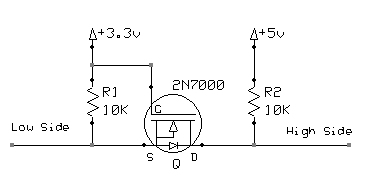
The ADXL343 is also powered at 3.3V this would require a voltage level converter on the shield from the 5V of the input test board.
See link
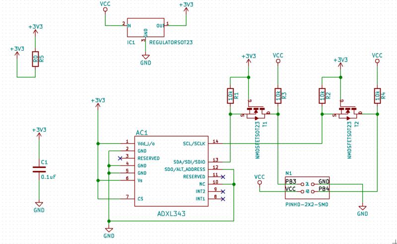
To add the sensor component on the PCB I had to manually create a footprint changing the pads so that they could be milled with a 1/64 tool, that is 0.4mm distance between pads. 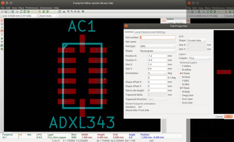
Here the PCB: 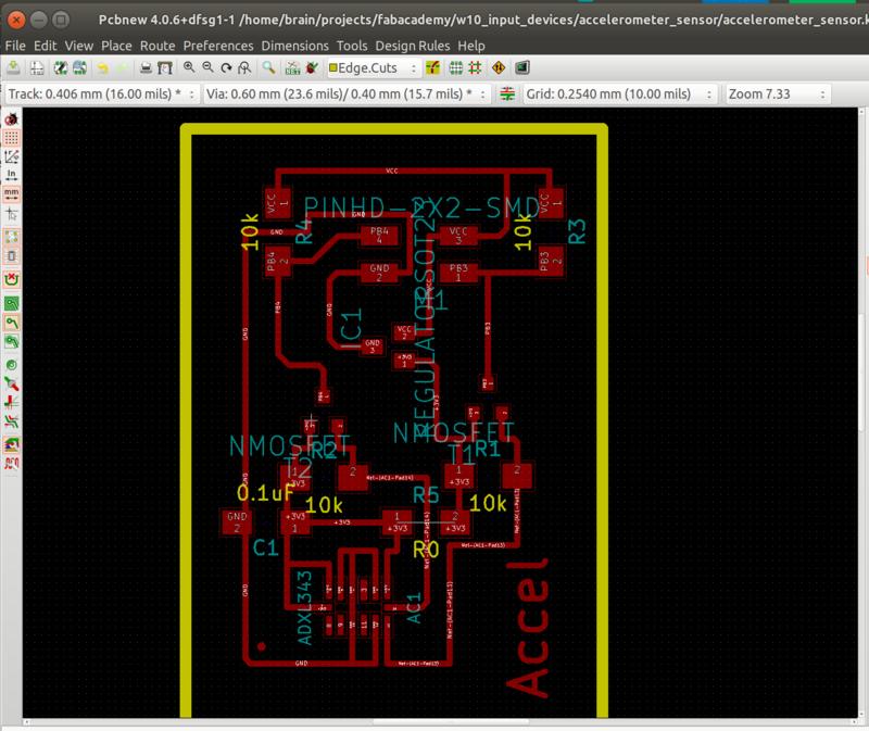
Download KiCAD project and GCode (.zip archive: KiCAD project, .png and .rml files)
At first when I tried the code examples after building the board I was unable to get any response from the ADXL343 so I followed various debugging steps. I was not sure if the problem was in the the fabrication of the board, the soldering of the chip or in errors in the voltage level converter logic.
1) In the code I was able to isolate the problem to this section where the ATtiny44 after sending a message is looking for an ACK from the ADXL343 to pull the data line SDA down: char I2C_master_write_byte(unsigned char byte) { [...] // // check for ACK // SDA_write(1); SCL_write(1); I2C_delay(); if (pin_test(SDA_pins,SDA_pin) != 0) { // // no ACK, return 1 // return 1; }
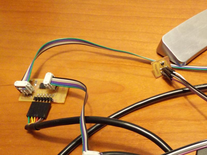
2) I started checking with an oscilloscope the various lines on the accelerometer board.
I connected my sensor through a breadboard to have simple access to the signals.
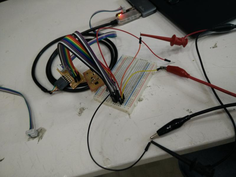
By checking different lines until the ADXL343 I could confirm that the board soldering and the 3.3V logic conversion was correct. 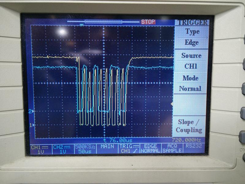
3) I decided to re-solder the ADXL343 and try again.
I had confidence that the chip position and quality of the second soldering was better that the first one.
The board before the un-soldering. 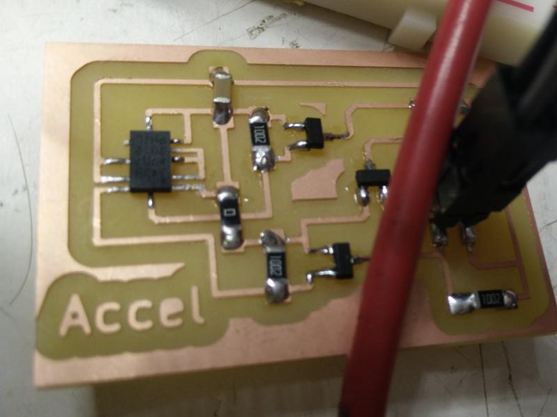
The board after the new soldering. 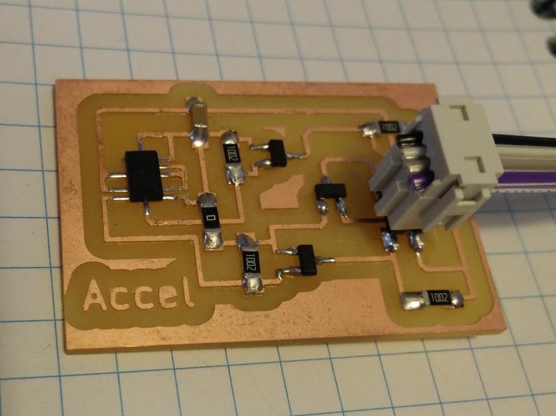
Unfortunately from the code debugging and from the oscilloscope I could see the same same errors. Here things get confused …I looking back I believe that I actually fixed part of the problem but probably there were some other issues with the pin wiring at this stage.
4) I decided to try the sensor on an arduino board and with the Wire library to see if there was any issue with the code.
Here things started working! :) 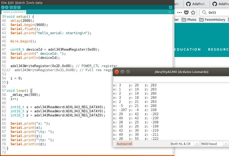
5) Finally I connected the sensor to the original input test board and without making changes to the original code it started working!
Download examples source code Arduino and AVR C (.zip archive: KiCAD project, .png and .rml files)
Heartrate sensor device
See the details of this in the separate page for heartrate sensor for the final project.
Lessons learned
- Be careful with the pin numbering in you board sockets and headers. If you’re creating interchangable components it is better to establish a pin convention, make it explicit and documented.
- Mark the ground header pin on the board headers for easy wiring.
- Oscilloscope is a useful tool for debugging your signals.
Next steps
- Test an heartbeat input sensor
- I’m curious to try step response sensors and pressure sensors.