Week 13: Networking and communication
This week we followed the Networking and Communication class(http://academy.cba.mit.edu/classes/networking_communications/index.html) (see video here)
This page is about the individual assignment.
The production process for all the boards described below followed the same processes documented in week 6 (design with KiCAD, .png conversions, using mods) and week 4 (electronics production, milling PCB and soldering)
Create a I2C bus
Simple master/slave bus
I had a previous week I already created and debugged a I2C connection for the accelerometer sensor with an ATtiny45 and Arduino board.
I plan to use the Wire Arduino library for my ATTiny45. Nick Gammon’s blog has an excellent blog post to document the use of he I2C protocol and the Wire library.
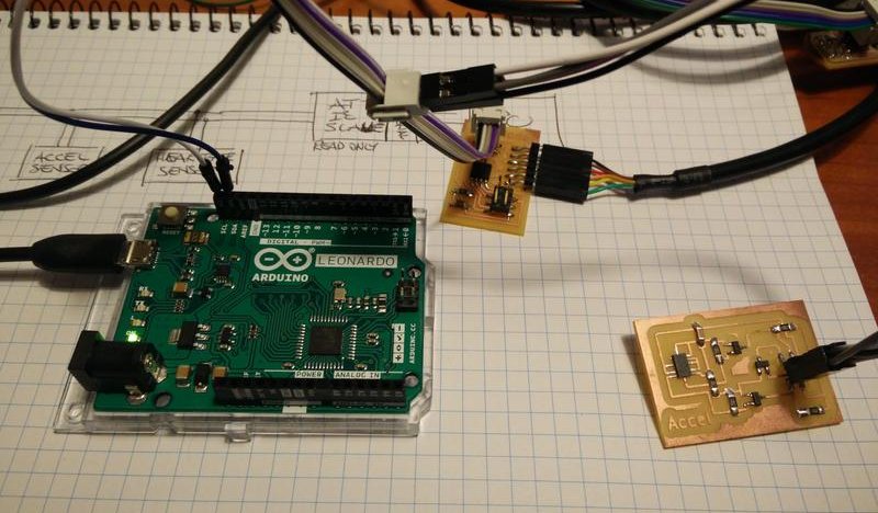
I created for this assignment two ATtiny45 boards with just a I2C interface and a serial interface for debugging.
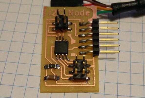
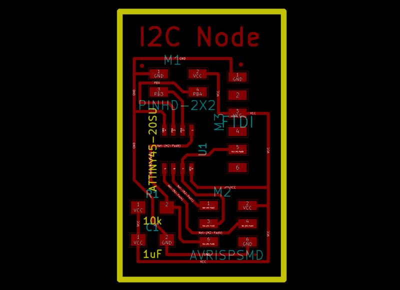
Download KiCAD project and GCode (.zip archive: KiCAD project, .png and .rml files)
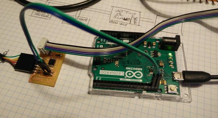
The first example is made of a simple master-slave configuration
ATtiny45            Arduino Leonardo            PC
(I2C master) —————> (I2C slave)      =====>  (serial)
AVR-libc            Arduino lib
In this scenario the Arduino slave just forwards some characters to the serial port.
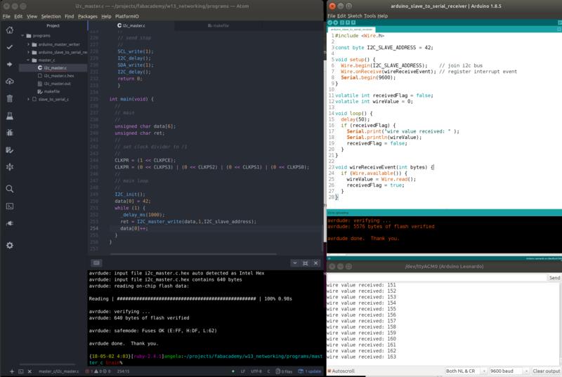
The slave implementation uses interrupts to receive the data (the interrupts should be as fast as possible to avoid race contitions). Later in the main loop we send the data back via serial port.
Download Sources (.zip archive)
It is necessary for the main loop to be faster than the interrupts frequency otherwise we loose some data like in the example below. 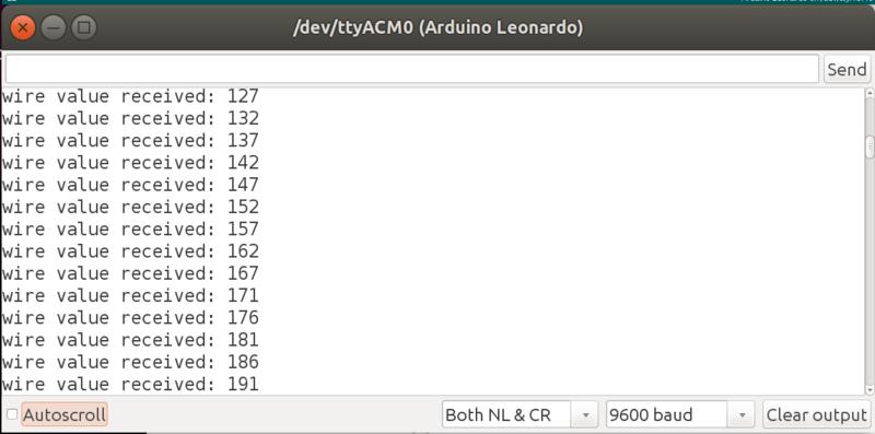
One master, two slaves and sensor data bus
In the second example I decided to add a ADXL343 accelerometer on the bus.
ATtiny45            Arduino Leonardo            PC
(I2C master) —————> (I2C slave)      =====>  (serial)
AVR-libc       |    Arduino lib
               |
               |    ADXL343 Accelerometer
               ———> (I2C slave)
In this scenario the ATtiny carries the task or reading accelerometer data from the sensor and sending them to the Arduino board. Arduino slave just forwards some characters to the serial port.
It is important here that the Arduino slave address that we choose 0x2A must be different from the ADXL343 address 0x55
Master-slave communication between ATtiny
ATtiny84            ATtiny84           PC
(I2C master) —————> (I2C slave)      =====>  (serial)
TinyWireM lib       TinyWireS lib
In this scenario I built a master-slave setup brtween two ATtiny84 boards that I’ve been using for my final project.
The master board is the board that has the role of reading and analysing the heart-rate sensor, the slave board has the role of controlling different light patterns of DotStar LEDs.
I decided to build a simple scenario in which the master board sends an integer value to the slave board as could be an heartrate value.
I stopped using Niel’s I2C C code implementation and to look for other libraries that have a complete implementation of the protocol.
Various on-line documentation is a bit outdated or low quality so it took me a while to get to a working solution.
Only at the end I came to uderstand well this comparison table available here
Initially I choose the library SoftwareWire that could allow me to use any pin of the ATtiny but didn’t succed with it.
I also faced the issue of recognising late that pull-up resistors are needed when connecting two ATtiny boards (while they are not necessary when using an Arduino board). I also found here and here some good documentation on how to size correclty pull-up resistors.
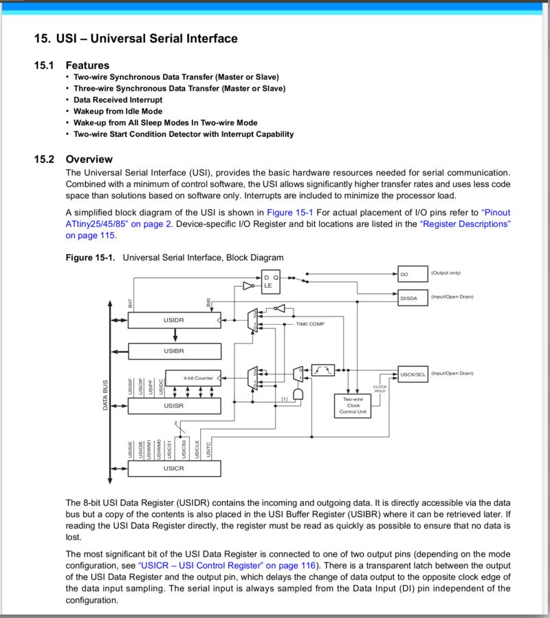
I decided in the end to use the dedicated SDA/SCL pins that come with hardware support on the ATtiny as documented in the chapter below of the datasheet. These are respectively the PA6/PA4 pins.
I ended up using the libraries TinyWireM for the master board and TinyWire for the slave board. Both libraries use an inteface very similar to the Arduino Wire library (see details below).
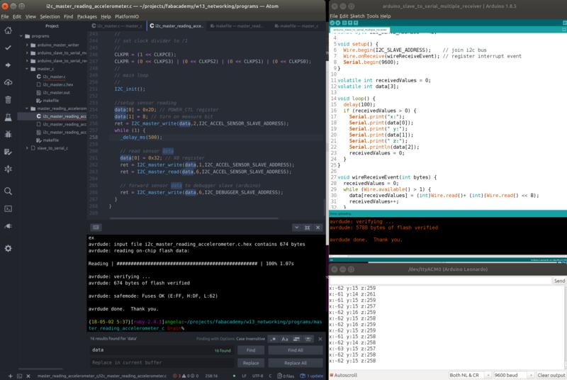
In this screenshot you can see me running the code for the slave (right side) and master (right side) with a serial monitor to debug the valuse being transmitted. 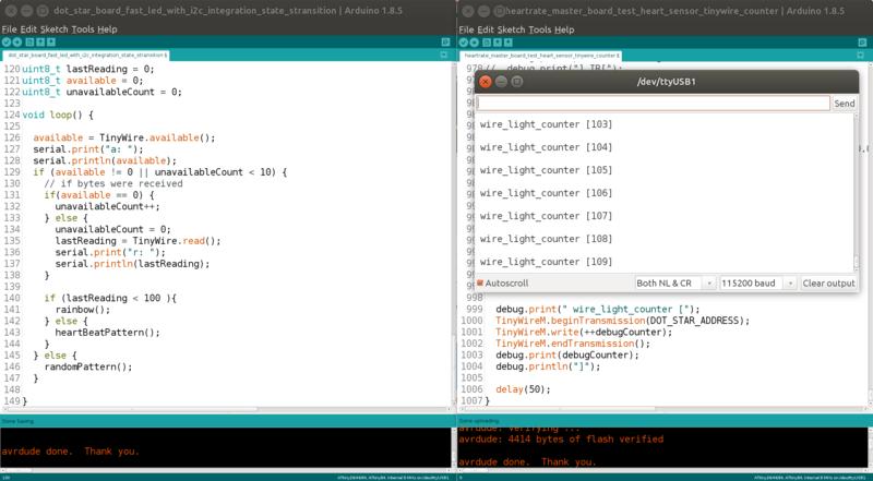
Master code using the TinyWireM library looks like the following
#include <TinyWireM.h>
[..omitted...]

#define I2C_SLAVE_ADDRESS  42
[..omitted...]

uint8_t byteValueToTransmit = 0;
void loop()
{
  byteValueToTransmit = readSomeValue();

  TinyWireM.beginTransmission(I2C_SLAVE_ADDRESS);
  TinyWireM.write(byteValueToTransmit);
  TinyWireM.endTransmission();

  delay(50);
}
This sample snippet shows the setup of the transmission beginTransmission(SLAVE_ADDDRESS), writing the values with write(BYTE_VALUE) and the end of request with endTransmission().
Slave code using the TinyWire library looks like the following
#include <TinyWire.h>
#include <twi.h>
[..omitted...]

#define I2C_SLAVE_ADDRESS  42
#define UNAVAILABLE_COUNT_MAX_TIMEOUT 10
#define VALUE_THREASHOLD   100

void setup() {
  [..omitted...]
  TinyWire.begin(I2C_SLAVE_ADDRESS);
}

[..omitted...]

void loop() {
  available = TinyWire.available();
  if (available != 0 || unavailableCount < UNAVAILABLE_COUNT_MAX_TIMEOUT) {

    if(available == 0) {
      unavailableCount++;
    } else {
      unavailableCount = 0;
      lastReadingValue = TinyWire.read();
    }

    if (lastReadingValue < VALUE_TREASHOLD ){
      typeAResponse();
    } else {
      typeBResponse();
    }
  } else {
    notReceivingDataResponse();
  }

  delay(10);
}
This sample snippet shows the setup of the bus using the same slave address with begin(), checking the presence of data coming from master with available() and the actual reading with read().
This code is also able to handle the situation in which the master is slightly faster/slower and to be reslient in case of short interruptions of the communication of UNAVAILABLE_COUNT_MAX_TIMEOUT times the loop is called.
One extra note on the slave side is that when using TinyWire together with SoftwareSerial they end up conflicting on the use of the interrupt on the PCINT0_vect vector (see details on interrupts here).
Linking everything together...
[...omitted...]
"/tmp/arduino_build_687301/../arduino_cache_751804/core/core_attiny_avr_ATtinyX4_cpu_attiny84,clock_internal8_6b6d5fe56a52a1cf6f3398f4a18ca1e8.a" "-L/tmp/arduino_build_687301" -lm
/tmp/arduino_build_687301/libraries/SoftwareSerial/SoftwareSerial.cpp.o (symbol from plugin): In function `SoftwareSerial::read()':
(.text+0x0): multiple definition of `__vector_2'
/tmp/arduino_build_687301/libraries/TinyWire-master/twi.cpp.o (symbol from plugin):(.text+0x0): first defined here
collect2: error: ld returned 1 exit status
I ended up commenting the interrupt from twi.cpp during the sessions in which I needed to debug.
//// Interrupt Routine, triggered when SDA pin changes; for detecting Stop condition
//ISR( PCINT0_vect )
//{
  [...omitted...]
Download full Sources (.zip archive)
Here is a video of the working solution. First you can see the master board, then the slave board controlling the lights.
When the wire_light_counter changes between 0-100 the lights pattern changes to a rainbow then goes back to normal.
Lessons learned
- Setting up I2C network is simple and communication between eterogenous hardware and different libraries works just fine
- Pull-up resistors are needed on ATtiny based boards for the I2C bus
- Libraries that use the ATtiny hardware support need dedicated pins. Software implementations are generally less performant.
Next steps
- Create a network with an heartrate sensor
- I’d like to try a Blutooth module because useful for a tracker project