the satshakit board (bocoduino board)
I few yeards back I made a simpler version of this project with I used an Arduino Uno. I am aware I am not able to use an actual Arduino board for the final project, this is why I will make my own arduino. Doing it will be very useful because I might be able to reuse some old code from before and also I am already familiar with Arduino boards and language, so it should make the whole electronics part at least a little easier.
I decided to follow this great satshakit tutorial following the recomendation of Nico who's previously made it and also has amazing documentation. Making a satshakit makes total sense because it is basically a simplified Ardunio, with the same pins (even more free ones) and most of all is 100% compatible with Arduino language and libraries. A satshakit board is totally like an Arduino board, thus is possible to use the Arduino IDE without any modification which is perfect.
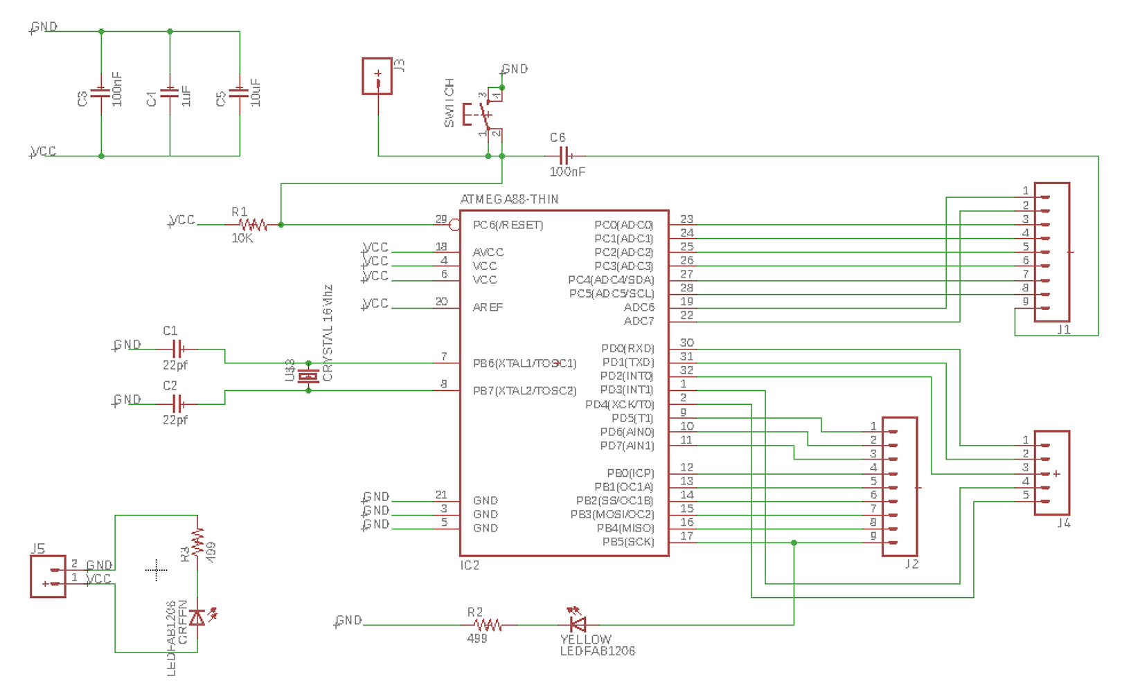
The Arduino Uno boards use two chips, but I will only be needing the ATMega328 microcontroller since this simplifies the board and I really only need the basics on the board.
Once I had the list of components I realised there are many of them I could not find in the fab library, so I added the Atmega8 Eagle and also the whole Sparkfun library for adding the components in Eagle. The ATMega328 in the library is does not correspond to the one I need beacause the spacing of the legs is diferent. Instead of modiying the component I used the AtTiny88-thin in the schematics beacuse it is the same as the ATMega328 in terms of pinouts, number of legs and spacings.
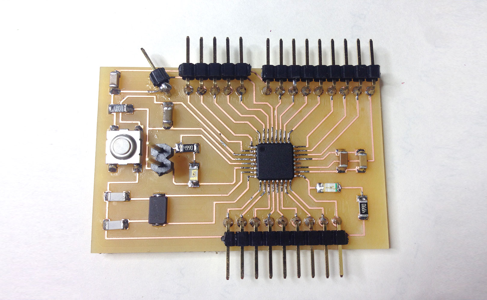
After a lot attention and patience my shematics and board files looked like the images below. I decided that this board would be called Bocoduino. It is important to say that I set the width and clearence of the traces to 12mil instead of to 16mil as what we normally use. This is because the legs of this particular microcontroller are closer together and it is the only way to do it. I guess I'll have to be extremely careful at soldering time.
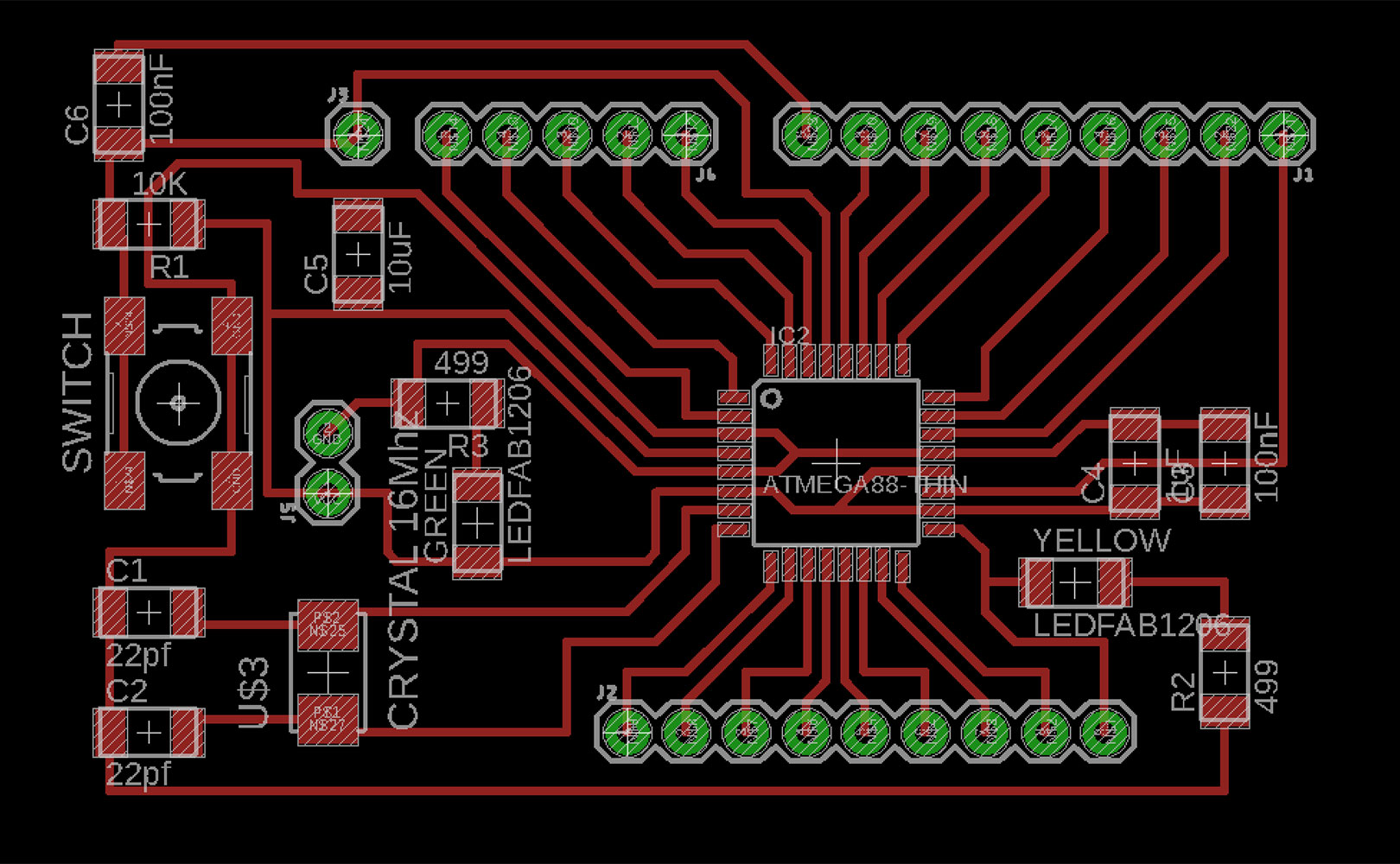
Milling took a while because it is a big board, but when the holes had to be drilled I realised they were being cut a few milimiters off. I quickly stoped the machine saving the board. I reviewd the png files and and remade the rml but the same thing kepts happening. The only thing that could have happened is that I was using the old version of FabModules and somehow this was causing a displacement of the holes.
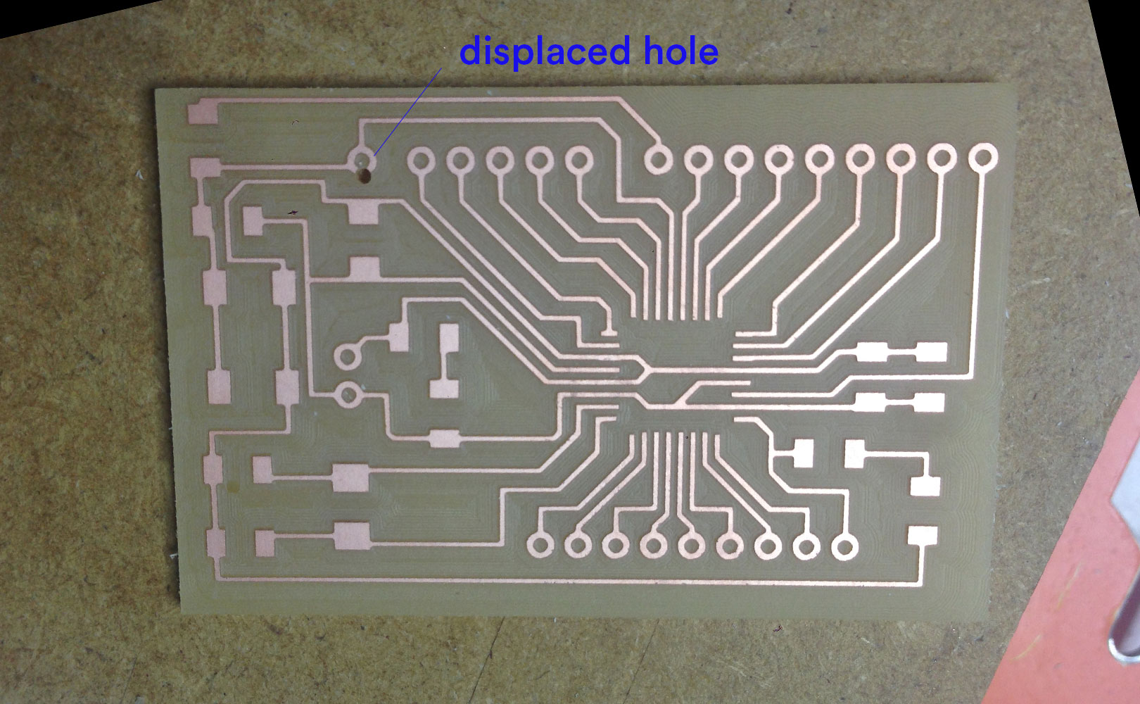
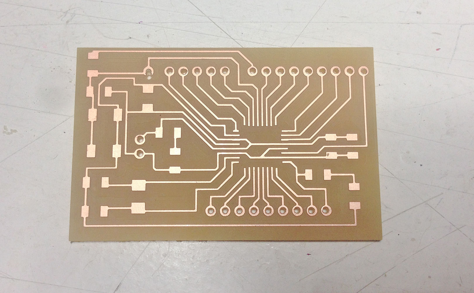
In order to fix this issue I decided to drill the holes by hand, which was also a good oportunity to learn how to do so. I found it a quite unprecise method at first, the only downside is that the holes are a bit tight, but overall I am fairly happy with this solution. Milled and drilled Bocoduino board below:
Result of the Bocoduino once solded in the image below. Overall it was no problem solding the components but there are two things to remark:
- Because the ATMega328 is so small I put a little bit of flux before soldering to fix the components and later proceeded in solding the legs all at once. Finally, the paths were cleaned and defined using soldering wig.
- The pin with the wrong drill hole was too big so it was hard to sold. As a consequence, the pin is placed in a diagonal instead of straight but fortunately this is only an aesthetic issue.
I made a diagaram with the conversion of my pins to Arduino pins future better understanding and workflow:
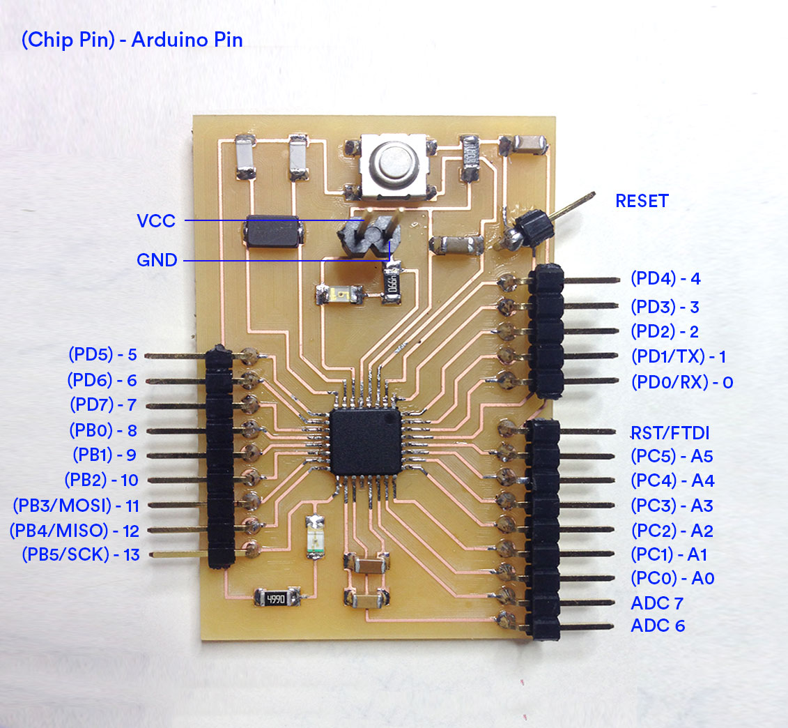
ATMega328 pinouts:
Files:
Bocoduino schemtics(.sch)
Bocoduino board(.brd)
Bocoduino traces ready for milling(.rml)
Bocoduino pads ready for milling(.rml)
Bocoduino cutout ready for milling(.rml)
programing the bocoduino board
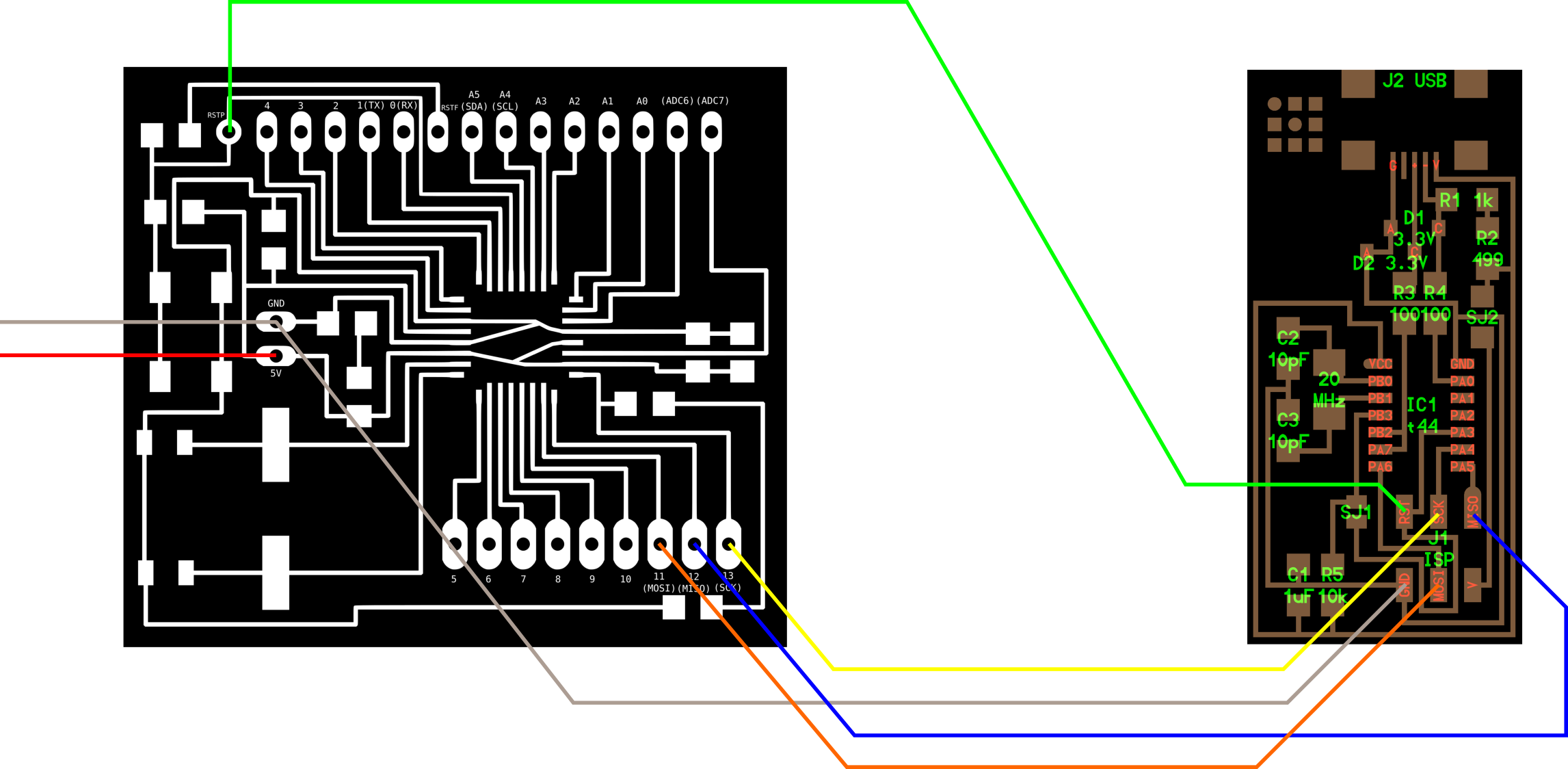
In order to program the Bocoduino and guided by the satshakit tutorial I started by replicating the connections from my board to the AVRISP programmer. The only difference is that in the tutorial they use the USBTinyISP and I am uisng the AVRISP instead.
Image below shows how to connect the board to the USBTiny in order to progam it:
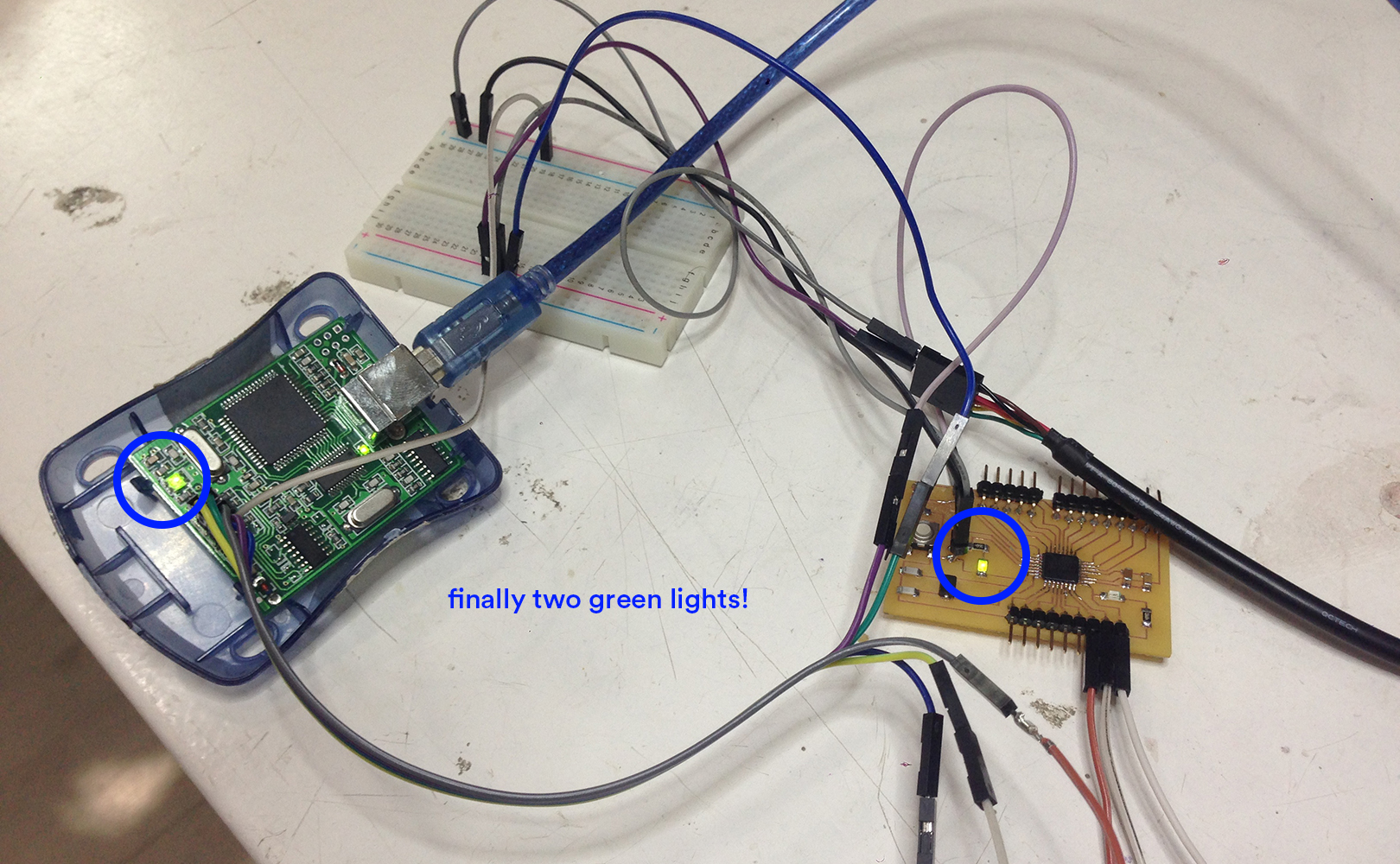
After doing the very same thing I wasn't able to program my board. The same error message in the Arduino consoloe kept appearing: "check connections" and also the light in the programmer apeared red. I did check the connections, but I kept and kept getting the same error.
Finally, and after lots of diferent tests, we discovered that the issue was that we werent connecting the VCC. Apparently it is not necessary when using the USBTinyISP but it is when programming with the AVRISP.
Afterall, I was able to Burn the Boatloader in Ardunio connecting everything as in the image below. In the Arduni IDE I set the board to "Arduino Uno", port to "usb-serial", and programmer "AVRISP mkll" and finally I adequately burned the bootloader!
At this point I was convinced that I was ready to start coding the Bocoduino, but I soon realised I wasn't right. As soon as I tried to test the board with the Arduino Blink example I kept geting errors in the arduino's console saying something along the lines of "can't make connection, efuses...".
I researched and tried to solve it, as well as some poeple in the lab. I tried burning the bootlader again through differnet methods but still kept getting the same error, I also modified the efuses manually and set them to the right ones, but no luck. Finally, I decided to follow the same tutorial Nico did as he had the very same issue as me. I follwed the setps carefully and magically it worked. I can finally say that I am ready to start programming the bocoduino board!
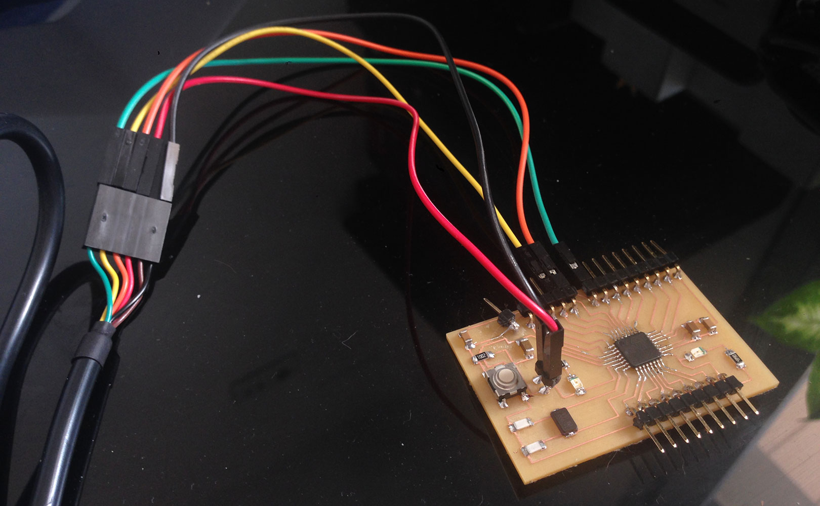
Below, an image of the Bocoduino connected to my computer through an FTDI cable. This is how I'll be sending code to the board from now on:
outputs board
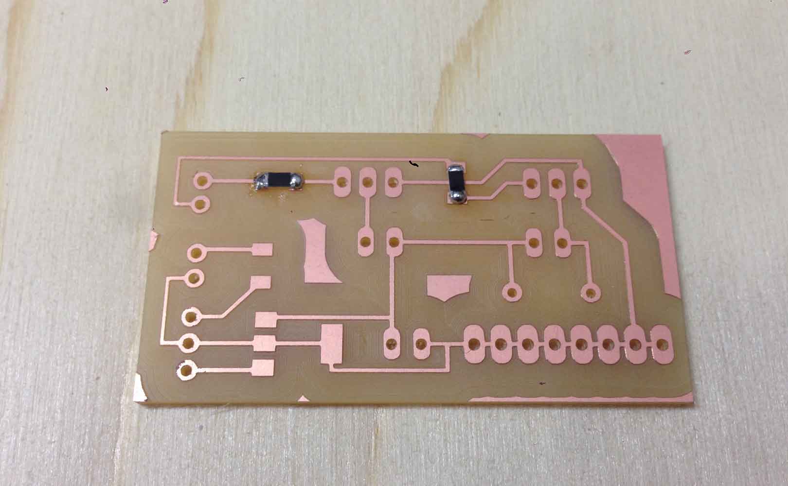
Once the Bocoduino board was ready and programmed I started making the Components board. This will be the Board where all the inputs and outputs of my project will be connected to.
First things first, I listed the main components I needed to include, and from there started figuring out the rest. I knew that this board had to have:
- Neopixel LED's
- a solenoid valve
- normal LED strip (in case the Neopixel ones don't arrive on time)
- extra GND pins (the bocoduino board only has one and it is not enough)
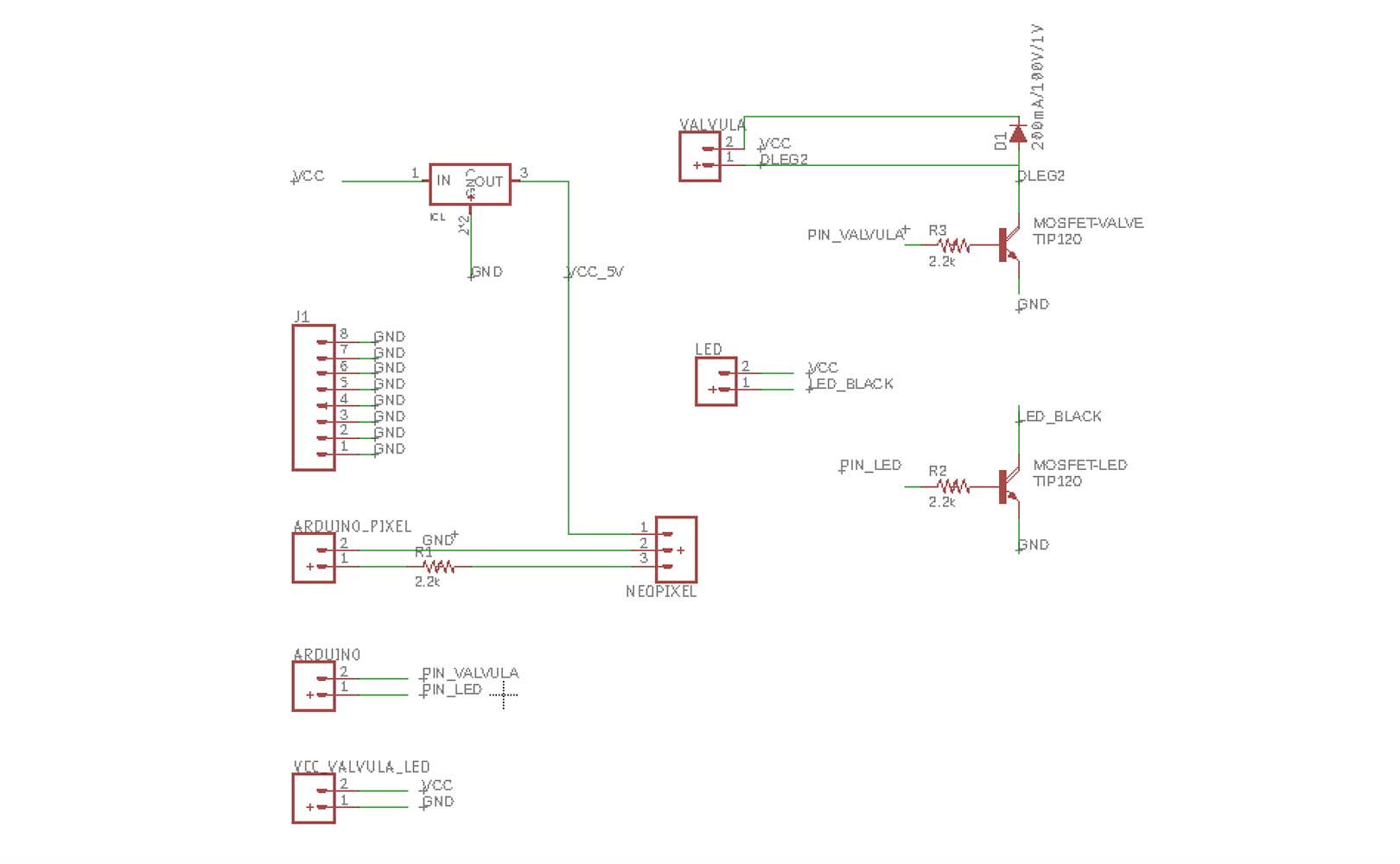
After listing the main components it was then easier to add the others I needed in order to keep everything without explosions, suchas as resistors, diodes and capacitors. I have double checked everything as my electronics will be powered by a 12V power supply, which must be outputed as 5V, this is why I used a voltage regulator and two mosfets paired with the valve and LEDs. I also had to investigate how to connect the mosfets(image below) and the neopixel ring I bought (datasheet here)


In the images below a snapshoot of my Eagle files, both the schematics and board.
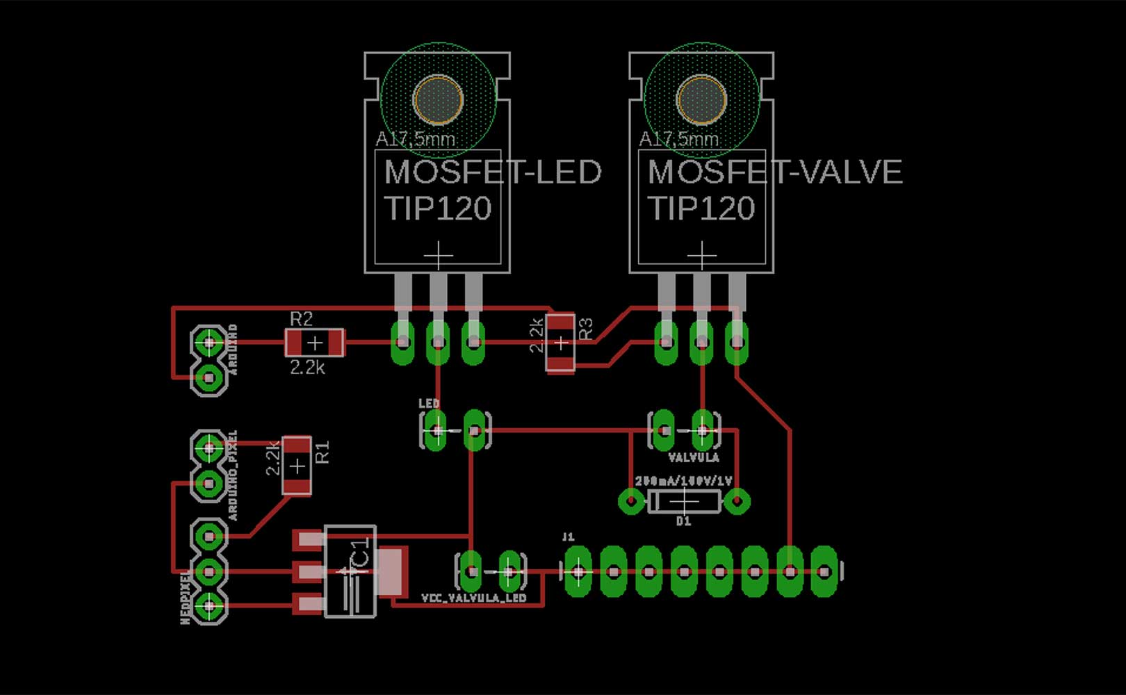
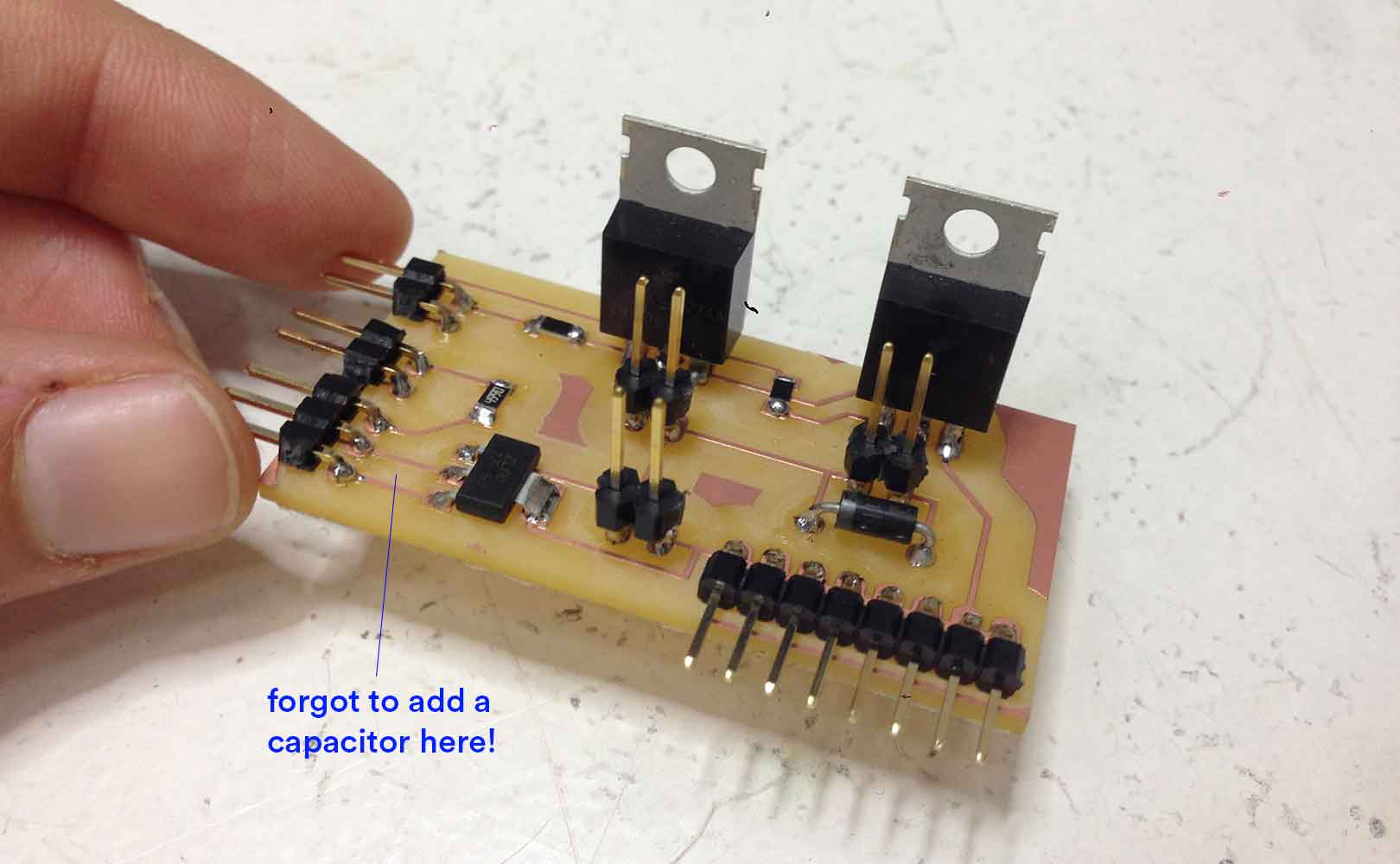
I guess that after all the boards I have made, I am finally getting the hang of it, because this has been the first time which I did not have any issue doing it. I felt confident during all the steps and the board came out from the milling machine exactly as I wanted it, even the holes were in their right place. So I proceeded to the soldering.
After the board was solded with all the components, I tested the connections and everything seemed right... except something. The voltage I was getting out the VCC was 12V instead of the 5V I needed. Then it is when I realized I had forgoten to add a capacitor between the the voltage regulator and the VCC pin. Luckily I had enough empty space inbetween the components, so I was able solder one on the last minute!
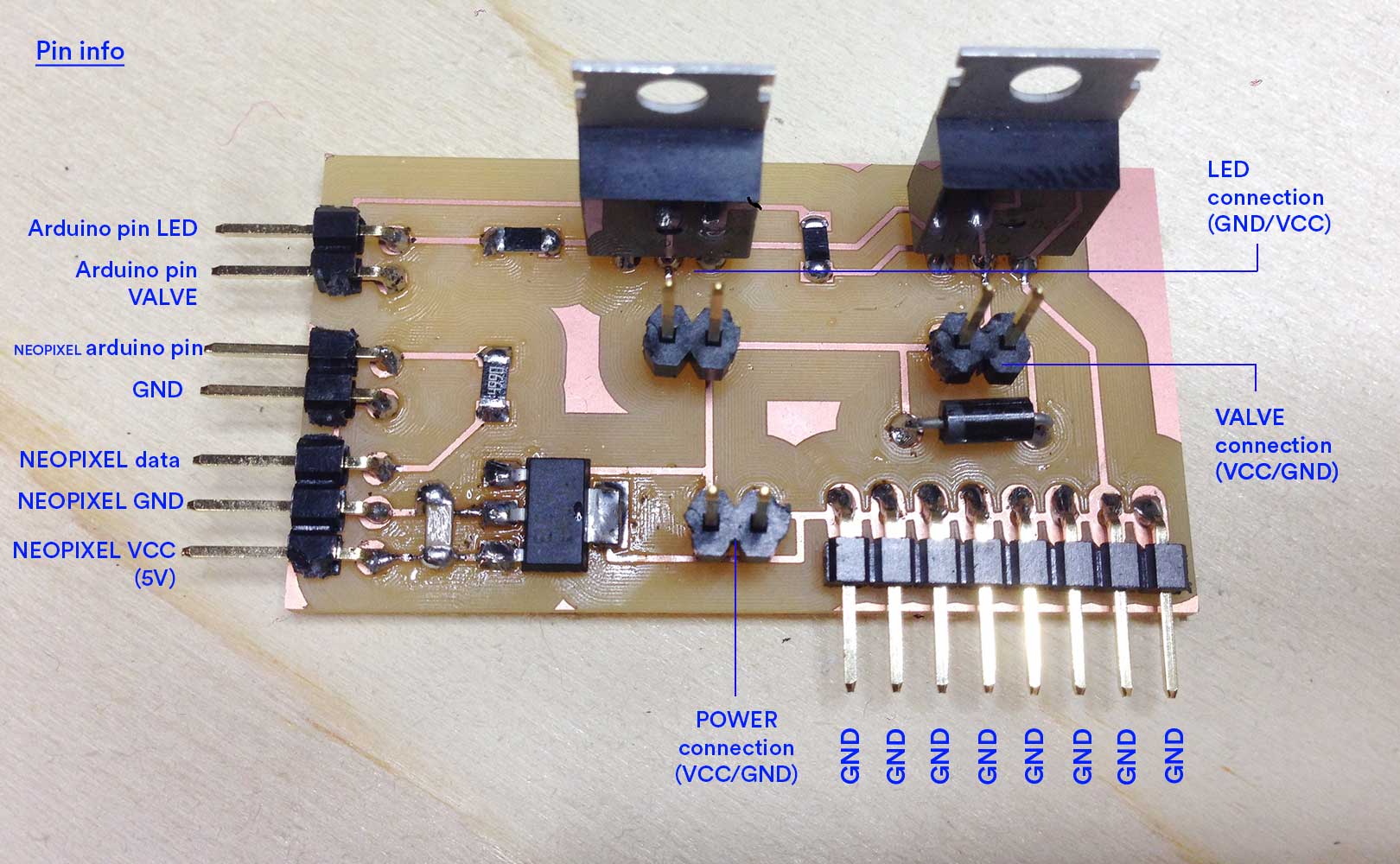
Once I made sure the board worked fine, I made this helpful diagram below to quickly know the pinouts when I forget.
When I started connecting all the inputs and outputs I realised I needed more VCC pins as I only had one outputing 5V. For a second I panicked, but Esteban remembered me that I could just do a mini board with simply solded pins and connect them to the main VCC so that they all become so. See fix below:
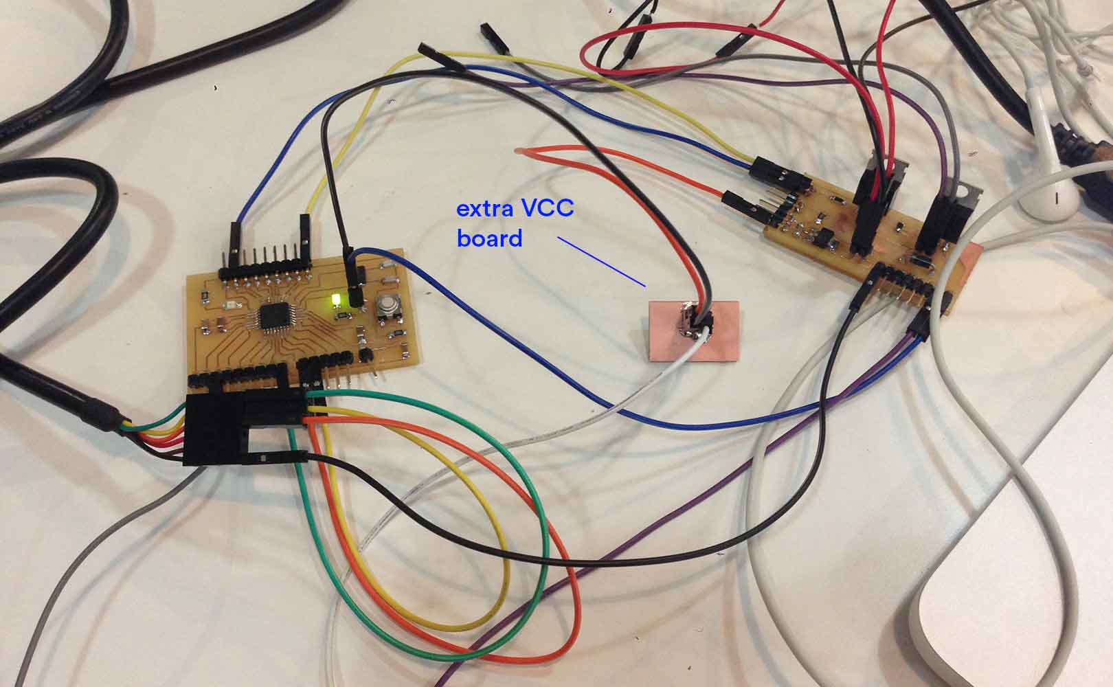
Image of all the components connected to the boards and working fine:
IMAGE OF EVERYTHING CONNECTED AND WORKING GREAT.
Files:
Outputs board schemtics(.sch)
Outputs board board(.brd)
Outputs Board traces ready for milling(.rml) MISSSSSSSSSSSING
Outputs Board pads ready for milling(.rml) MISSSSSSSSSSSING
Outputs Board cutout ready for milling(.rml) MISSSSSSSSSSSING
http://fab.academany.org/2018/labs/barcelona/students/marta-bocos/12-interface_and_application_programming.html
moisture sensor
My initial idea was to have live internet data as an input (through an API), and feed the plant acording to that. Unfortunately, I won't have enough time to connect the plant to the API, at least for now, so I have decided that I will feed the plant when it naturally needs it, through a moisture sensor. My plan for when I have time is to connect the plant to the internet.
In the (Interface and Programming assignment on week 12, I already tested and programmed the moisture sensor, so the only thing left to do now is to connected to the bocoduino and add it in the code so that it affect the behaviour of the valve and leds.
http://www.circuitstoday.com/arduino-soil-moisture-sensor
programming neopixels
https://learn.adafruit.com/adafruit-neopixel-uberguide/arduino-library-use
https://cdn-learn.adafruit.com/downloads/pdf/adafruit-neopixel-uberguide.pdf