Group Task
Electronics Design
Preparation
For this week's assignment we were asked to use the test equipment in our lab in order to observe the operation
of a microcontroller.
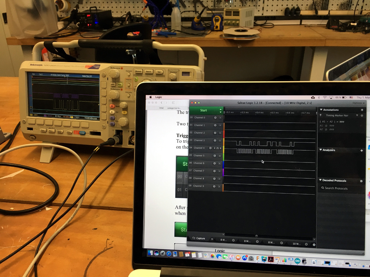
At our FabLab there are two advanced testing devices available:
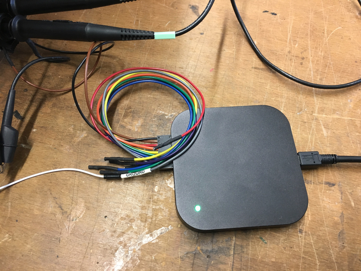
An digital oscilloscope and a logic analyzer
(Saleae logic analyzer product page).
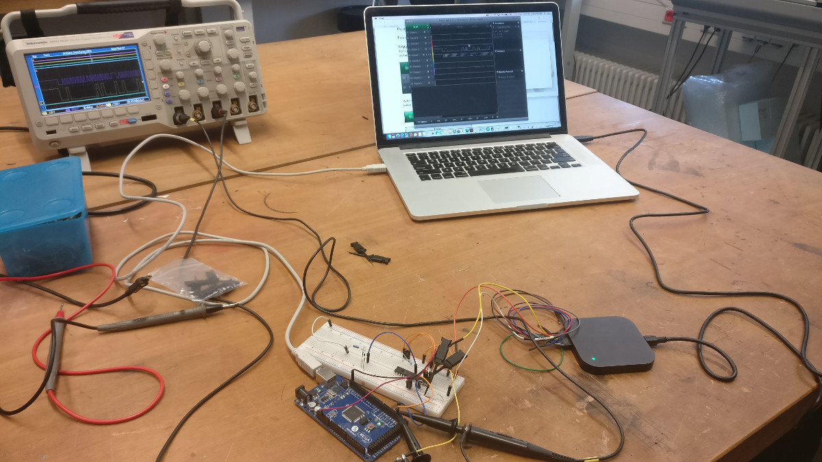
Test Application and Setup
As a simple test setup - just to get something that we can observe with them - we quickly
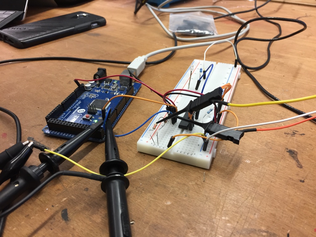
setup an I2C port expander.
We connected the MCP23017 (datasheet)
to an arduino Mega and attached the logic analyzer and the oscilloscope to the bus lines (SCL and SDA).
We programmed the arduino to operate the MCP23017 in order to blink an LED on one pin.
This generates some regular I2C traffic that we can observe with the test equipment.
Later we actually removed the blinking operation and just send a regular "turn on" signal.
This makes observation simpler as the signal is always the same.
Download the arduino-file (it is basically the MCP23017 libraries toggle example)
Results
The logic analyzer is used with its software also called 'Logic'. The interface displays several channels as and their logic state over time.
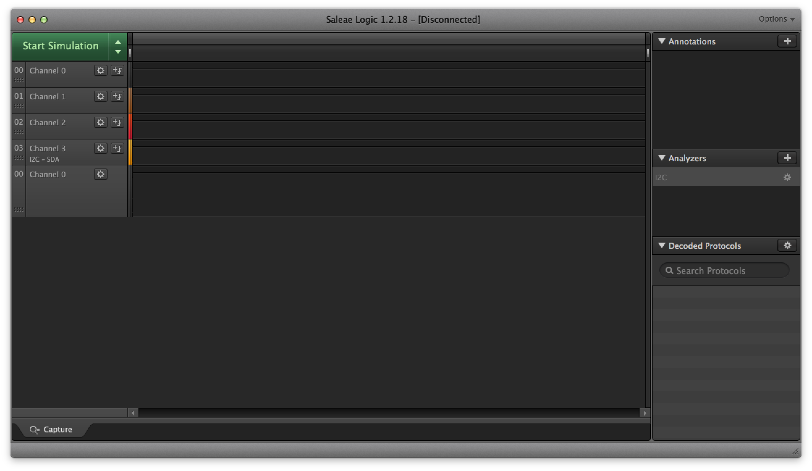
After taking a sample the signals are displayed and can be observed.
Also several bus decoders are available - in our case I2C - displaying the transferred bytes.
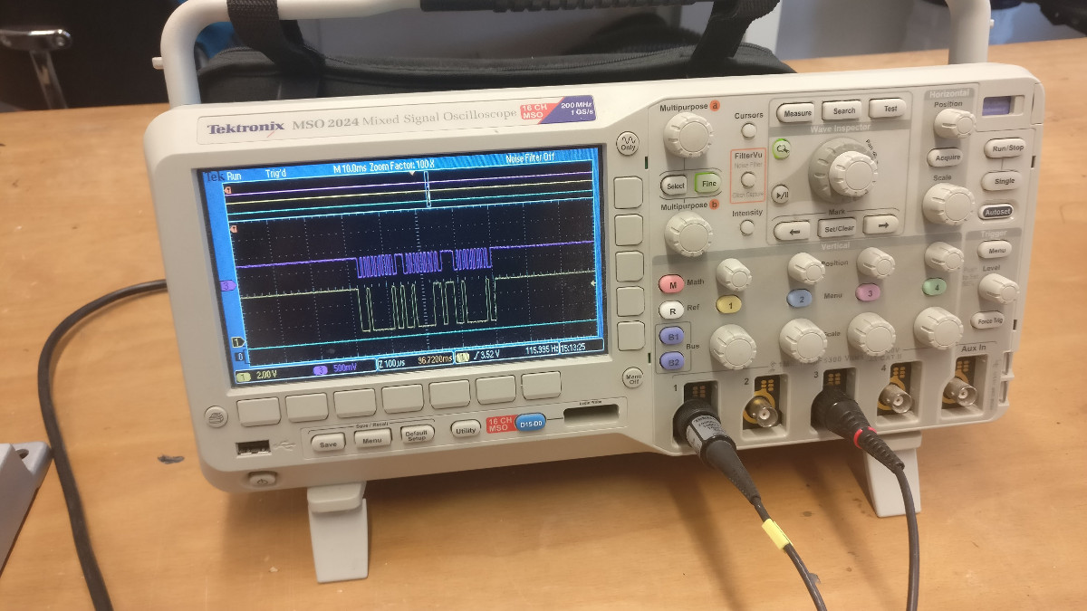
In fact - as expected - the oscilloscope shows the same signals (top and bottom switched).
However, the oscilloscope displays the bytes in hex representation and the logic analyzer in decimal.
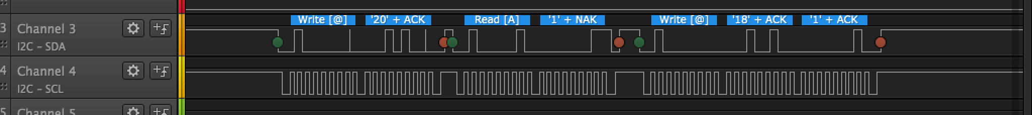
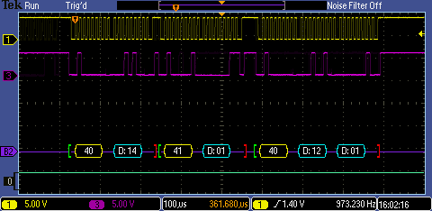
On both devices we can observe the following sequence
(here in hex, minus delimiters bytes, slash delimiters I2C transfers):
40 - 14 / 41 - 01 / 40 - 12 - 01.
The hole sequence is composed from three I2C transfers, we can reverse engineer that and cross check it to the
original code (library).
The first two transfers are a read operation to the OLATA register and the second sets the first bit of
the GPIOA register.
Later is the more important one as this actually turns on the LED.
The read is only required to preserve the other bits in the register.