Assignment 11
Output Devices
The last week we were asked to gain knowledge about output devices. Of course, an output device can be easy as a LED but gaining knowledge about other output devices is also importabt.
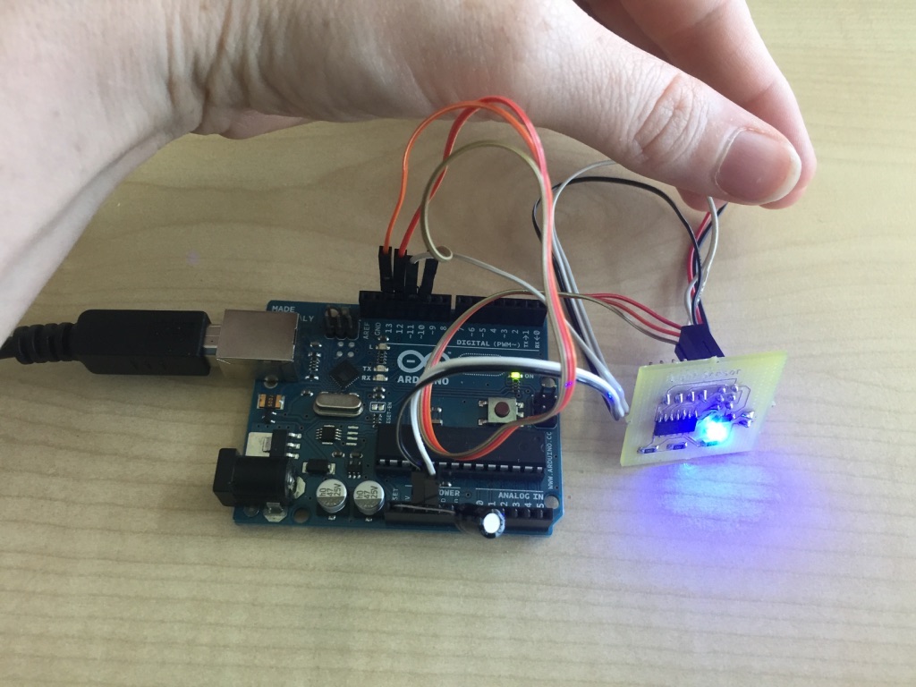
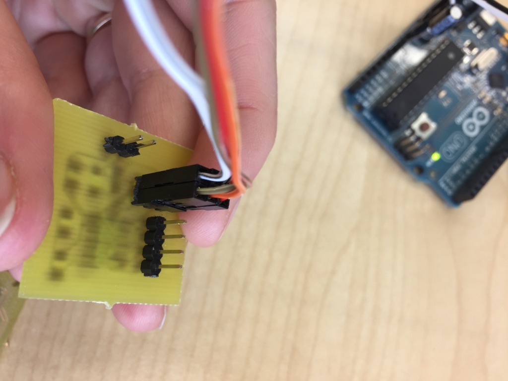
I decided to use the board and photoresistor from the input devices week in combination with an LED for an output device, that will turn on/off according to how much light the photoresistor captures.
Photoresistor and LED
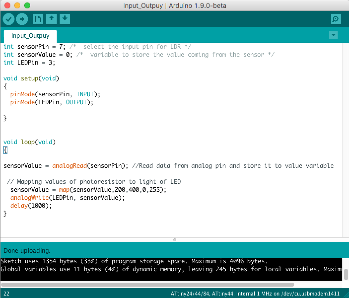
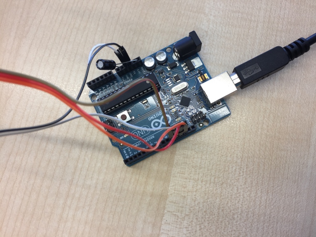
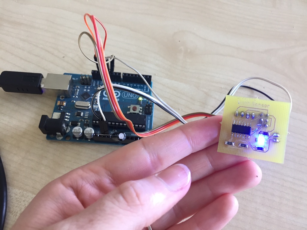
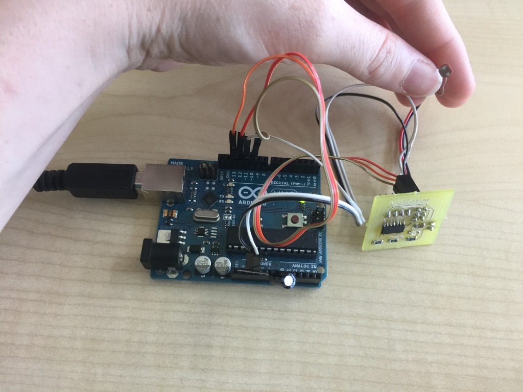
To explain the connection between the photoresistor and the LED here you have the code that was flashed on the board: You can see that photoresistor values of 200-455 are mapped to LED brightness values of 0-255.
                int sensorPin = 7; /*  select the input pin for LDR */
                int sensorValue = 0; /*  variable to store the value coming from the sensor */
                int LEDPin = 3; /*  select the pin for LED */

                void setup(void)
                {
                  pinMode(sensorPin, INPUT);
                  pinMode(LEDPin, OUTPUT);

                }

                void loop(void)
                {
                sensorValue = analogRead(sensorPin); //Read data from analog pin and store it to value variable


                  sensorValue = map(sensorValue,200,455,0,255); // Mapping values of photoresistor to light brightness of LED
                  analogWrite(LEDPin, sensorValue); //Set the brightness value of the LED
                  delay(1000);
                }
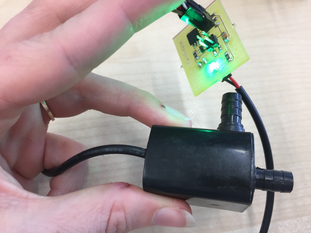
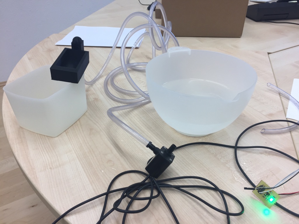
Waterpump as Output
For my final project I also build a board that was planned to control the waterpump of my christmas crib for the watering place. You can find schematic and board file of this board in the communication assignment week as I also used this board for a serial-bluetooth connection. For the output assignment I programmed this waterpump board additionally as another output device. Of course, I also followed the described procedure above, which means e.g. burning the bootloader of the attiny45 on the board first before programming it. Underneath you find the code of the Arduino file. for the board.
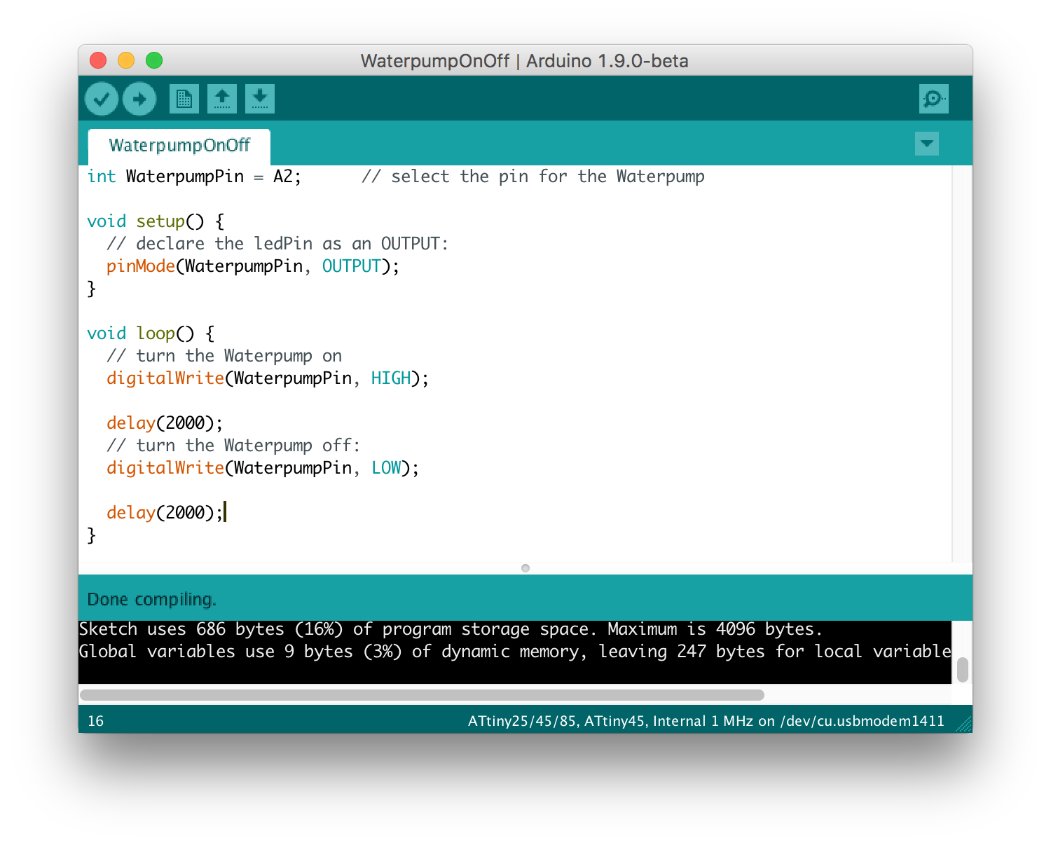
                int WaterpumpPin = A2;      // select the pin for the Waterpump

                void setup() {
                  // declare the ledPin as an OUTPUT:
                  pinMode(WaterpumpPin, OUTPUT);
                }

                void loop() {
                  // turn the Waterpump on
                  digitalWrite(WaterpumpPin, HIGH);

                  delay(2000);
                  // turn the Waterpump off:
                  digitalWrite(WaterpumpPin, LOW);

                  delay(2000);
                }
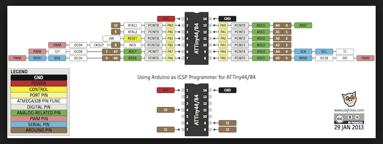
How the Microcontroller Datasheets & Pinouts helped