WEEK 15 & 16
MECHANICAL DESIGN
ASSIGNMENT DETAILS: Design a machine (mechanism + automation), including the end effector. Build the passive parts and operate it manually. Document the group project and your individual contribution.
WEEK 15 - INTRODUCTION
I can't speak for the rest of the group but I was a bit anxious about this two week assignment. We had lots of ideas but we had to remain realistic considering our fairly busy schedules. I am very proud of what we accomplished in such a short time. I think we have a good base now to build a unique machine.
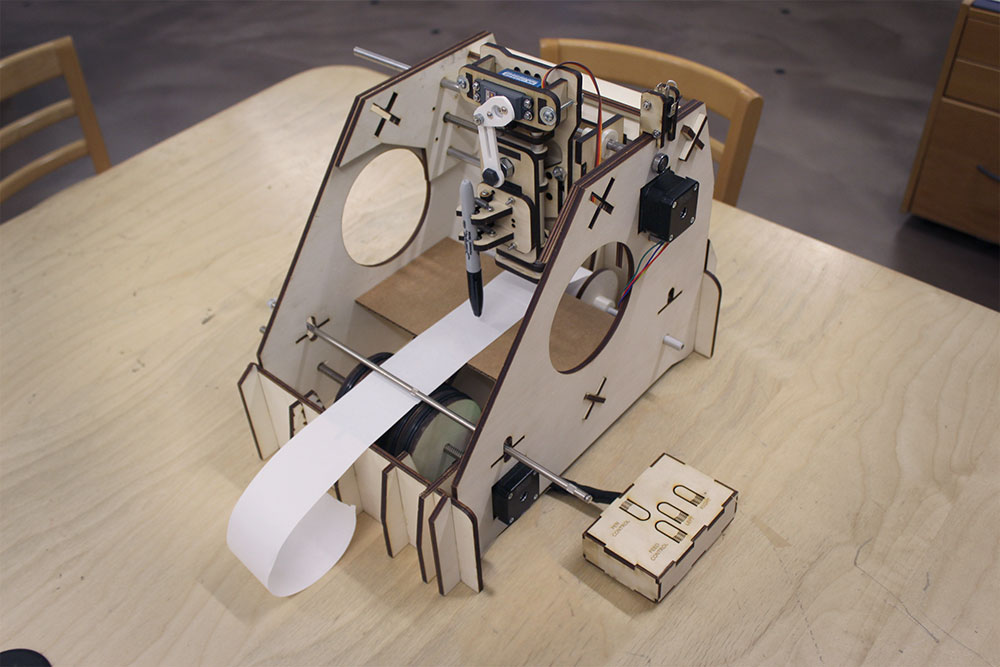
We bounced a few ideas out and settled on a drawing machine that worked like a conveyor belt.
We had a basic excel sheet to organize ourselves with but found we needed to be a bit more fluid and basically did not use it beyond our first meeting. Initially we divided the tasks up as such:
---> George - end effector
---> Marc - x-axis and electronics
---> myself - machine body, feed mechanism
Our fourth partner, Geoffroi, had some bad luck and had to miss the week. He helped with documentation and support but did not get a chance to be as involved in the machine design. Marc worked very hard on the electronics, made beautiful circuits to work with the Gestalt node. Along the way, as things do, something went wrong and his circuit would not be ready in time. We had to come up with a plan B as our time was close to being done what with full time jobs and other commitments which left us very little time to maneuver.
I had just finished working on the machine body so was available to help with initial electronics (Week 16) to help get the machine up and running for some tests. Not nearly as classy as what Marc was working on but I was able to get a few quick tests going while George worked on the X-axis. Marc put the finishing touches on the machine and packaged it nicely. If time permitted the idea would be to integrate his electronics and iron out the kinks.
Our machine is tentatively titled the GAM Machine which simply stands for Georg, Alec, & Marc
CARDBOARD PROTOTYPES
I really wanted to make the machine body using a press-fit construction. We agreed as group that we wanted this to be a simple design. I might have gone a bit overboard in my iterative process but it really served me well as far as my part of the project. I started designing in Fusion 360 and cut and made a few prototypes out of cardboard. This had two functions:
---> test strength of the design
---> open up a group discussion on where to place elements
---> 1st
The first prototype was rather simple. I felt it was a bit weak mind you I was working with cardboard.
As a group, we decided where the parts would go and what kinds of mechanisms we would use. échoFab has a lot of discarded electronics which made it easy to find gears and other components we could use. However, making a belt system would take a long time to get right.
---> 2nd
My next version had a few more legs. I also added support for the nema 17 linear drivers. In case we wanted to include a y axis.
This design still showed weakness. Any flexion would cause the body to warp. I needed to add more support so that it would not flex.
---> 3rd
I made one more cardboard prototype. I added a lot more support. It was a bit excess but what it lost in simplicity it gained in strength.
I actually started to think that a cardboard machine was possible at this stage. However, George had been making an amazing effector out of laser cut wood. It would not have matched.
After this prototype, we ditched any ideas that might have included a why axis. Too much work for the time we had. Our machine would be x-axis and we would use a feed mechanism for y.
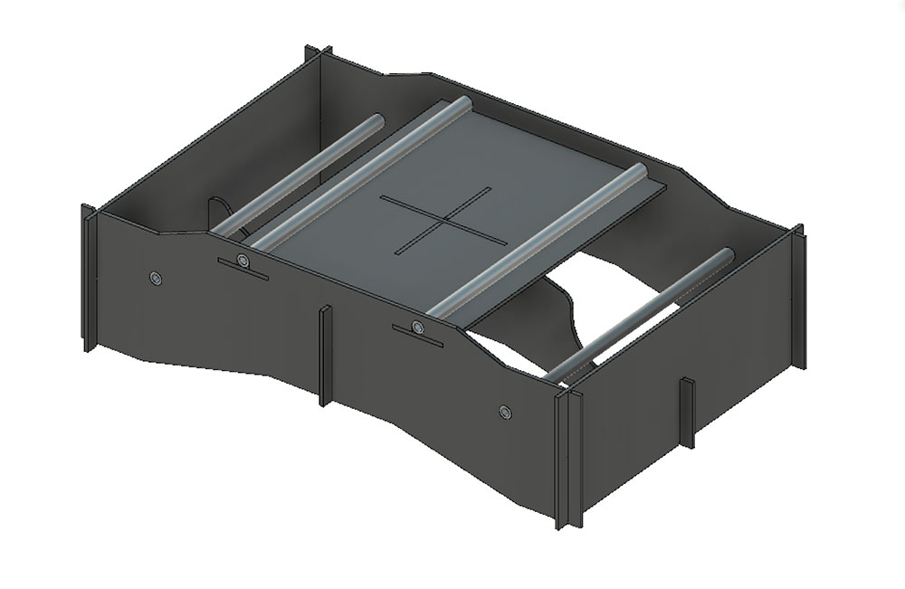
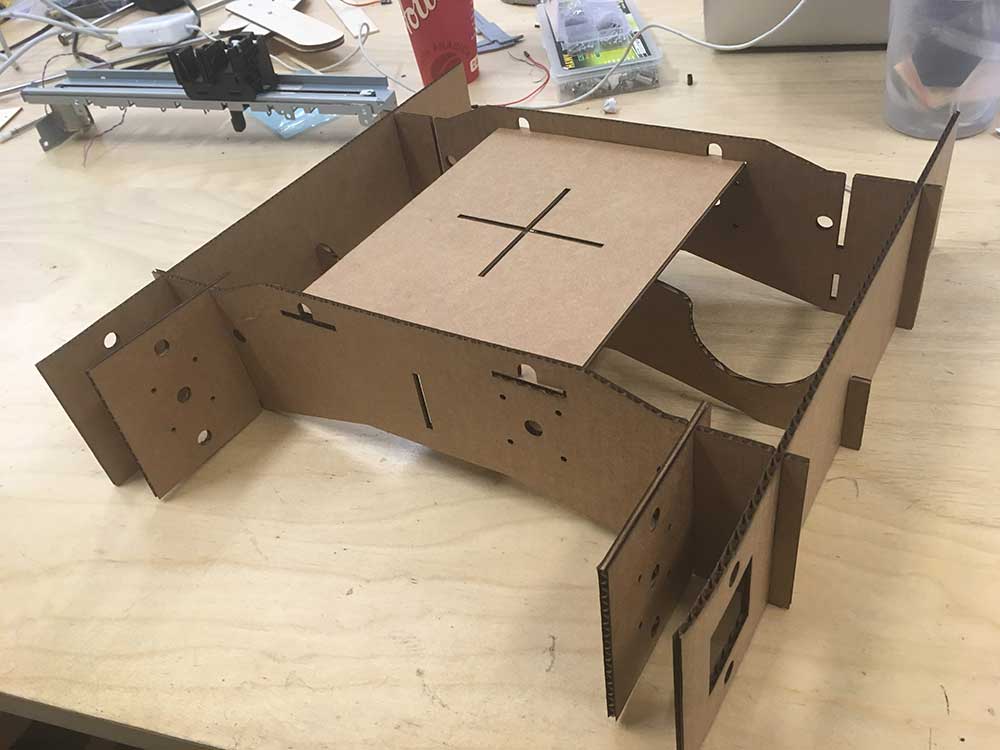
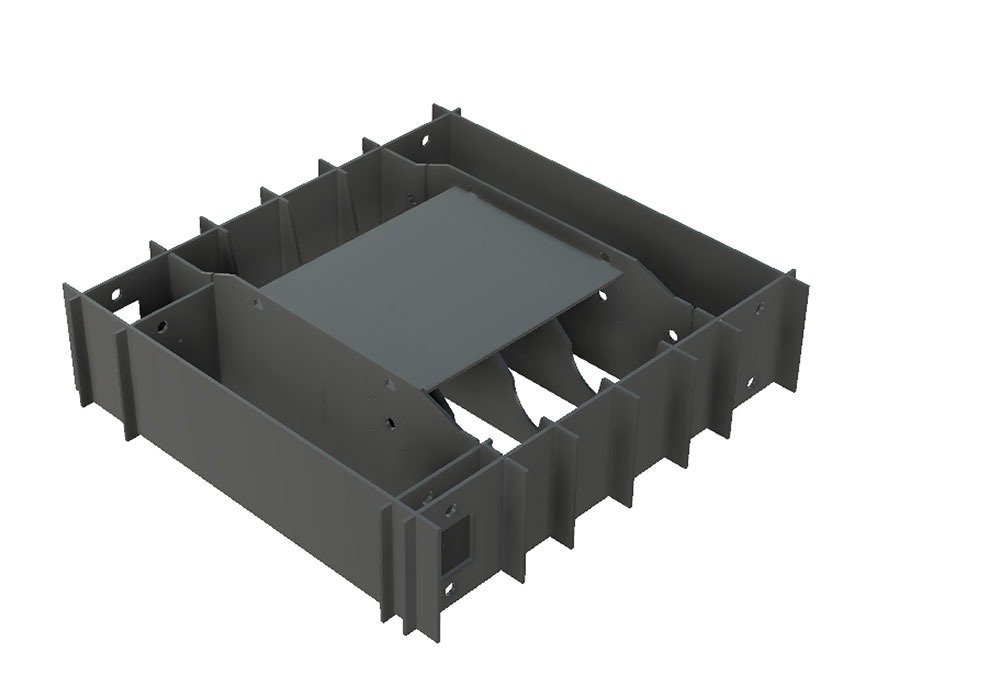
FINAL PROTOTYPE
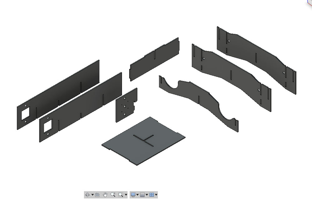
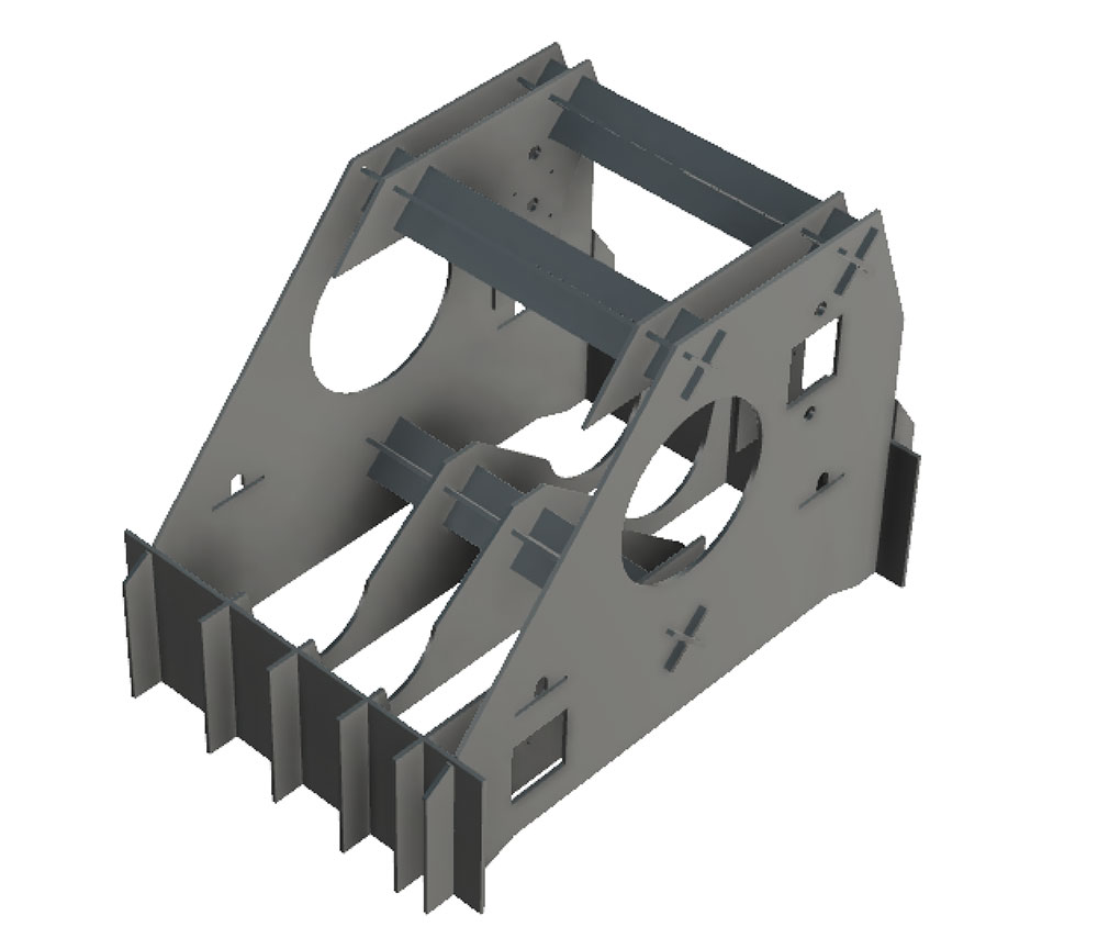
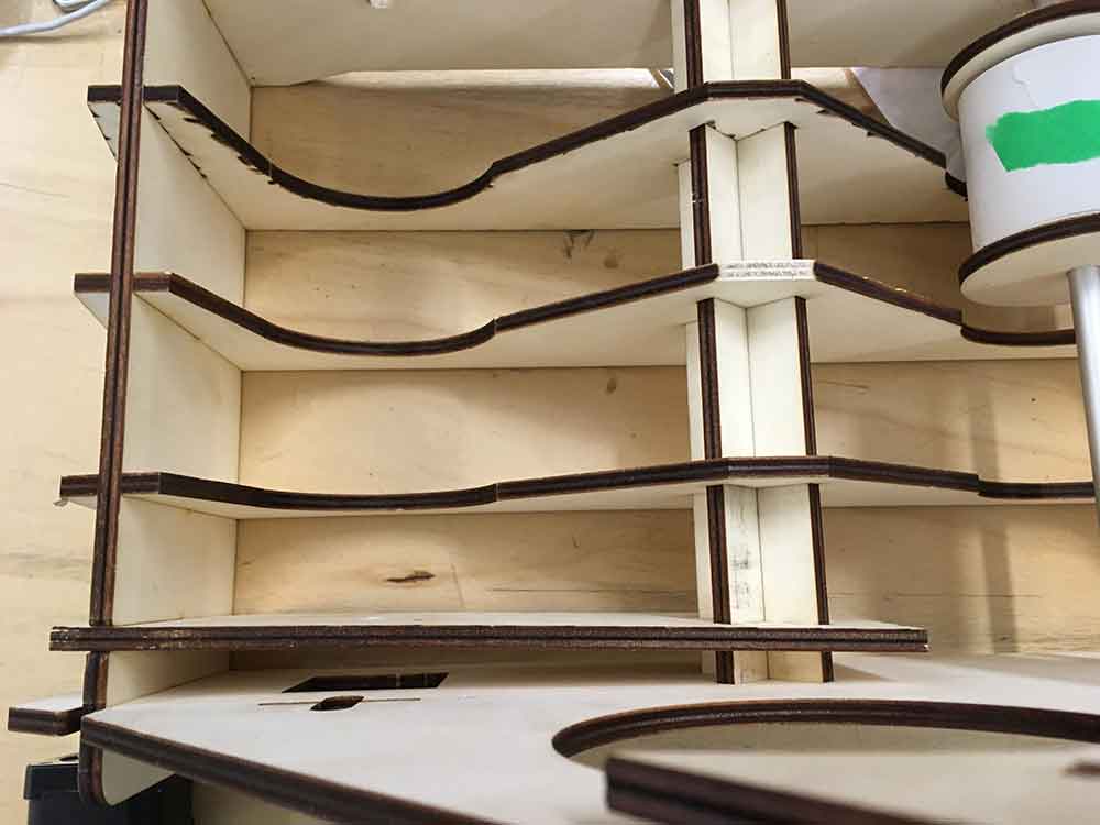
For the final prototype, I took what I had learned from the previous designs and included a feature from a previous assignment. Looking back at the Computer Controlled Machining week where I was experimenting with cross-brace / pressfit structures, I decided it would give this design a lot of added strength.

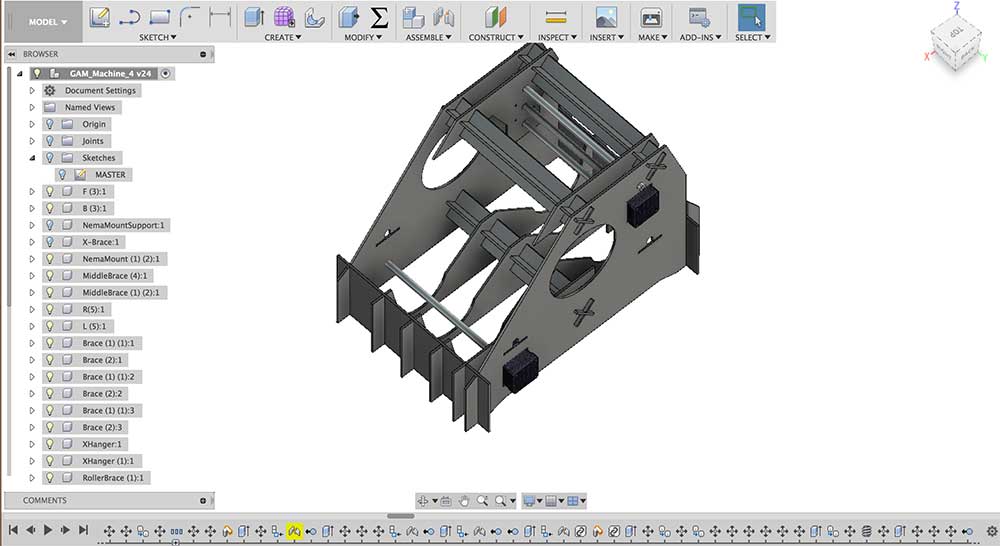
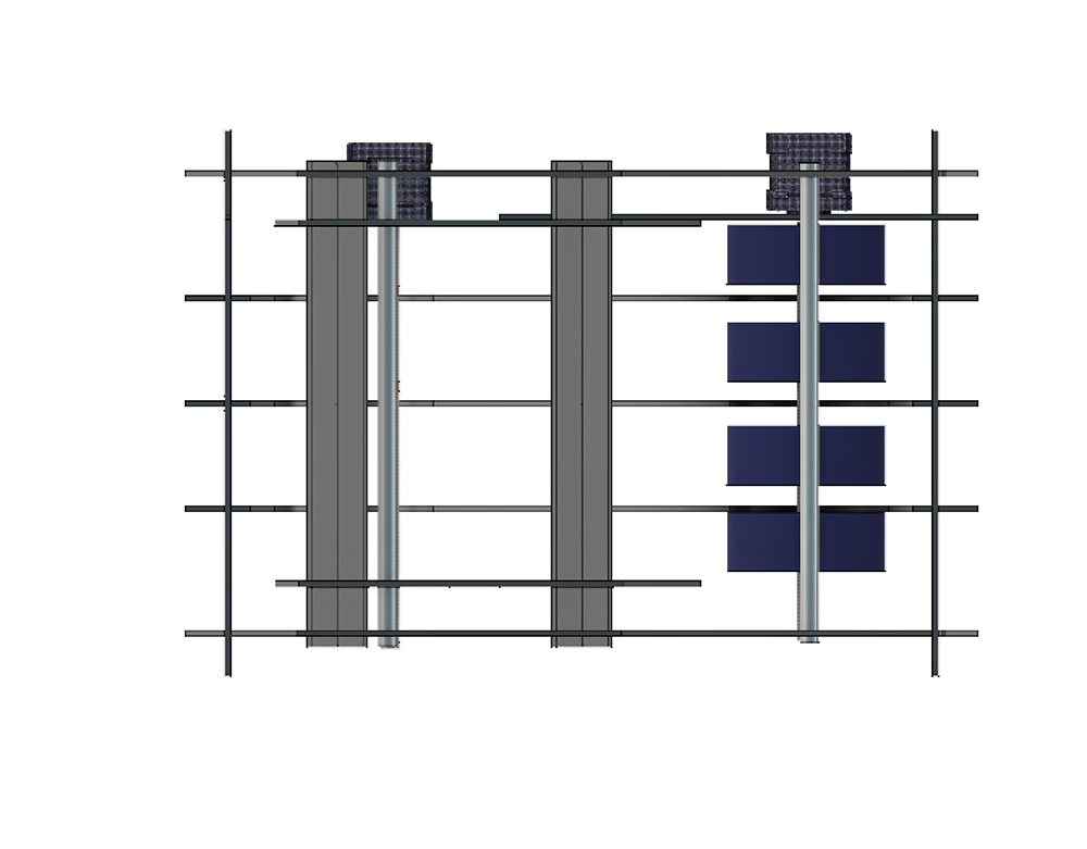
The other major design change was to move the x-axis up. We gave up on using any kind of rail system on the side of the machine and simplified things by just have a moving x-axis and a feed mechanisim in the front. Paper would be pulled by the feed mechanism and the pen would simply move along an x-axis. I retained the middle braces and all the mounting ideas from previous prototypes and simply made taller side-walls. I also added some extra support close to the Nema17 mounts.
Note: The Nema17 motors in these Fusion designs come were made using Antimony from the Computer Aided Design Week
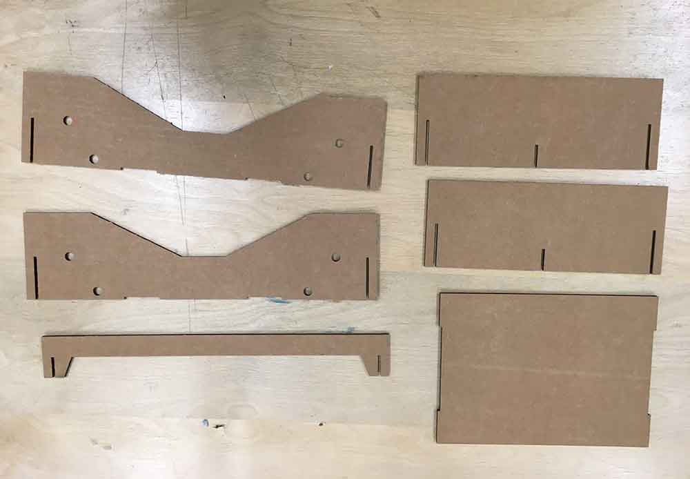
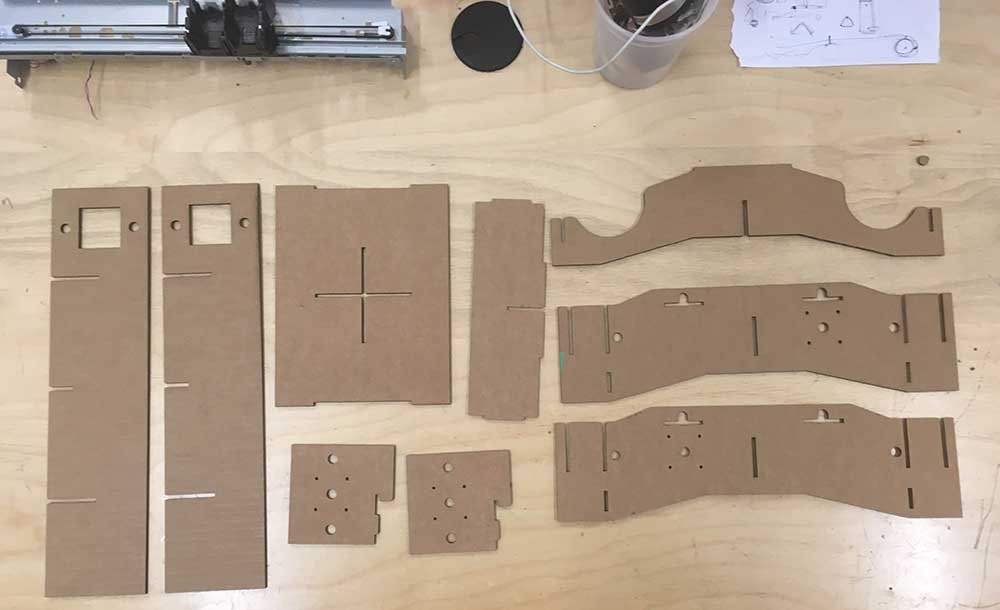
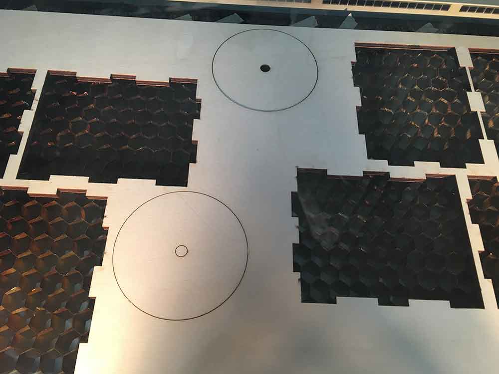
There are 10 unique pieces to this design with a total of 19 pieces that need to be cut plus an extra 14 wheels needed for the feed mechanism. A total of 33 cuts to do on a laser cutter.
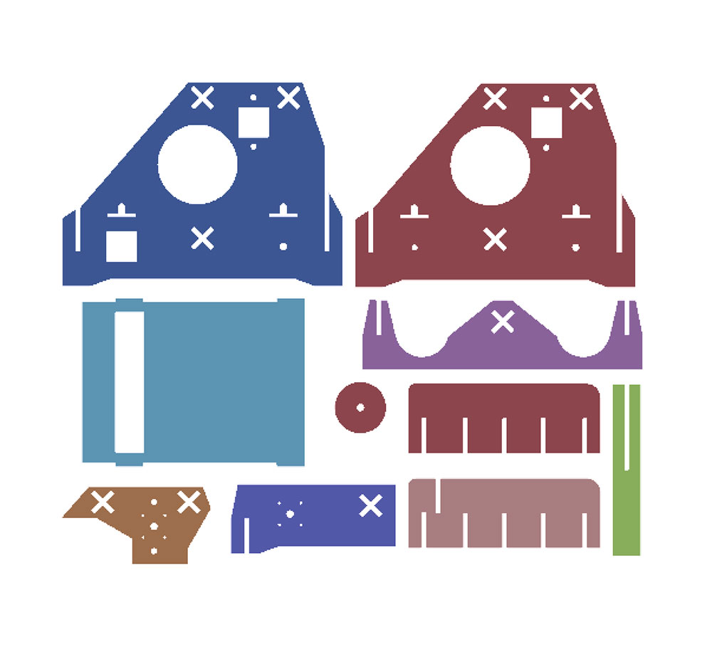
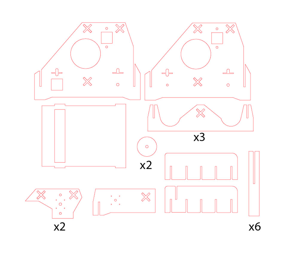
Note: The circles needed for the feed wheel are not included in the above drawing. The circle in the above image which needs to be cut twice is used to keep the roll of paper in place on the rod
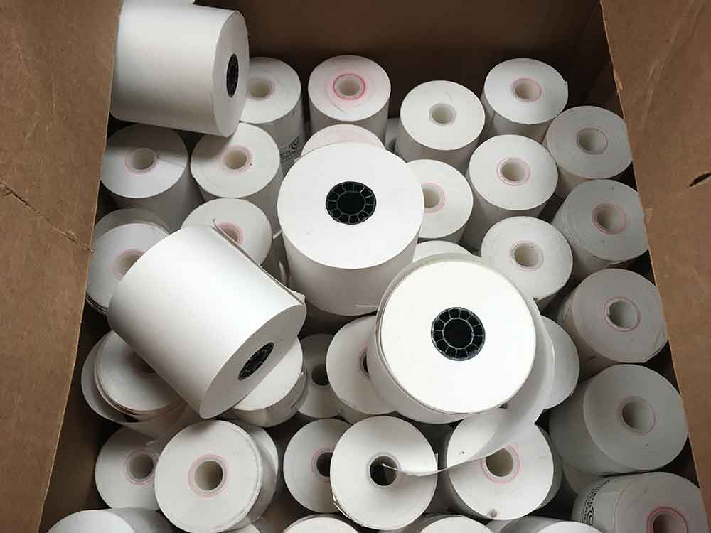
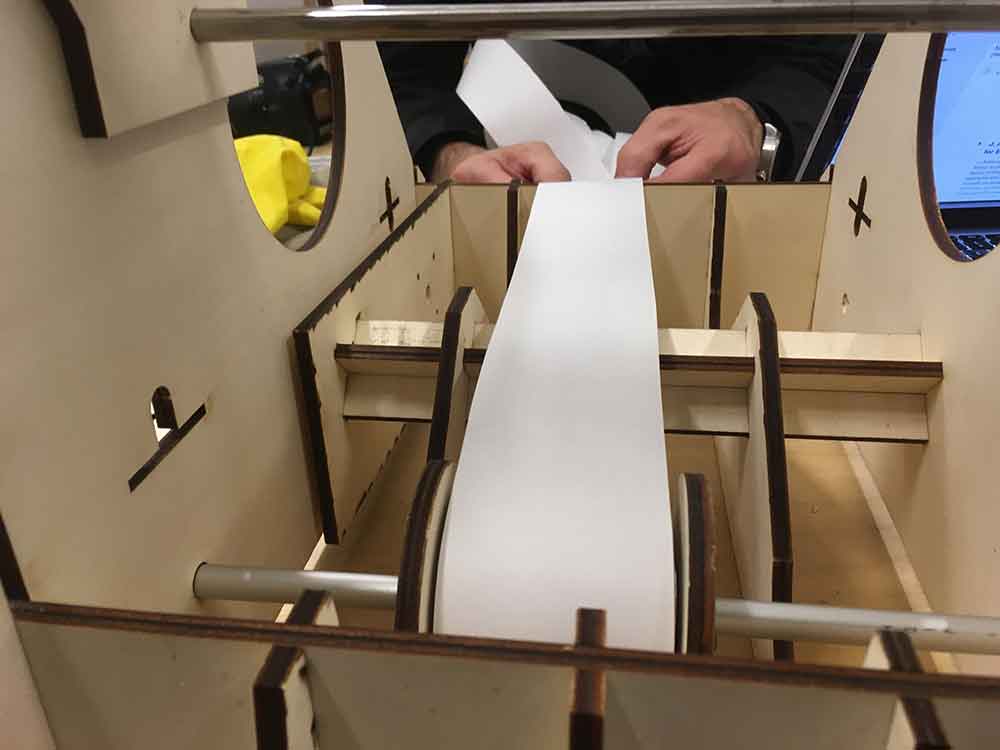
It turns out we had a lot of rolls of 3mm paper where I work. We decided that this would be the paper that we draw on. Our machine could draw on wider media but this narrow roll also makes it a bit more fun.
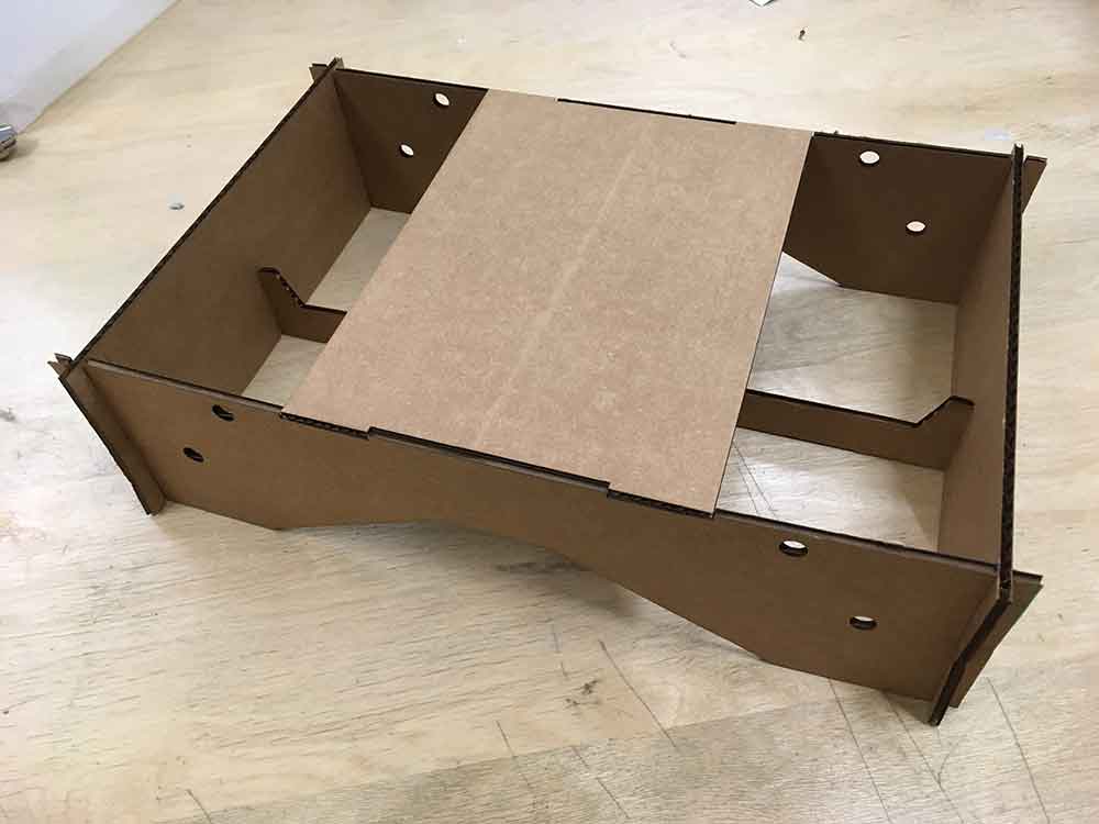
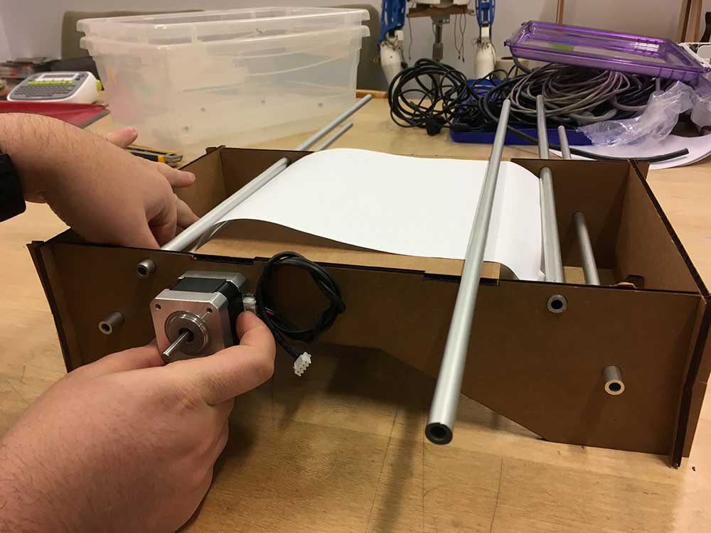
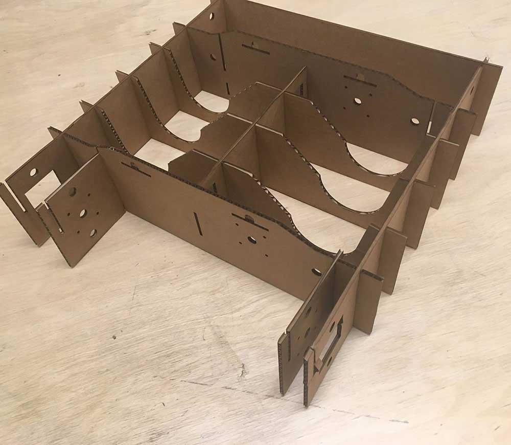
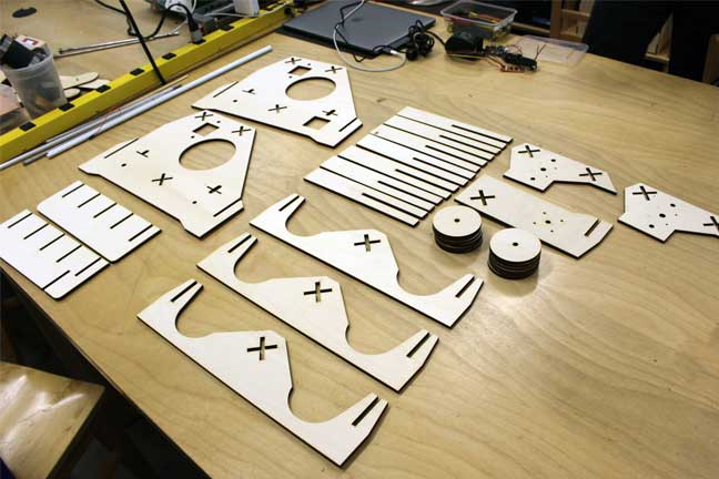
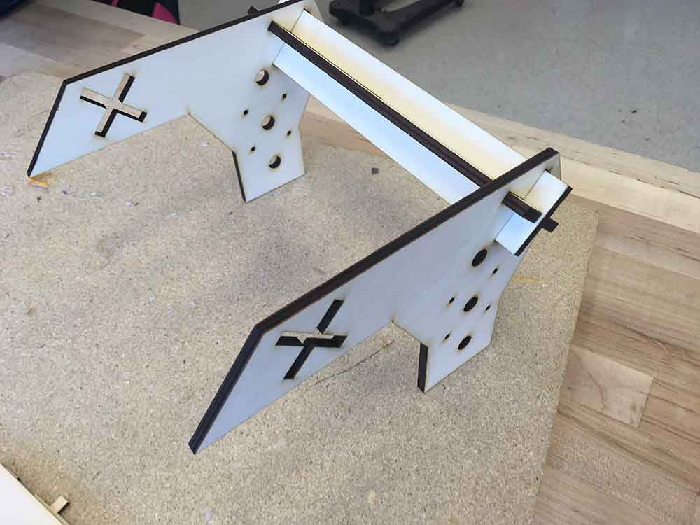
I started to assemble the pieces which I had cut at the LCC Fab Lab. I wanted to see how they fit before heading to meet the group. More specifically, I was curious to see how much strength the press-fit system gives.
We had to do a few measurements to see how the paper would move through the machine before building the feed wheel. One of our biggest concerns was to have the paper drift out of position.
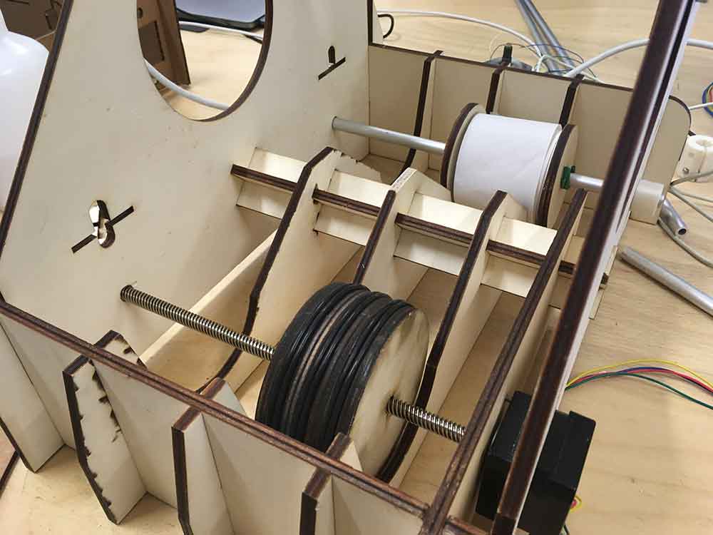
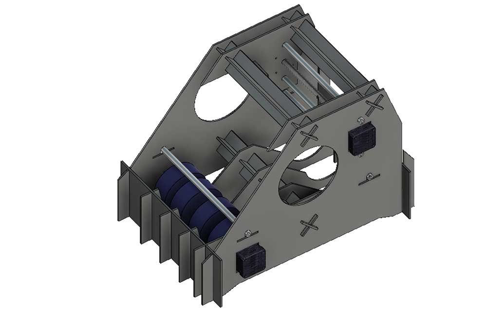
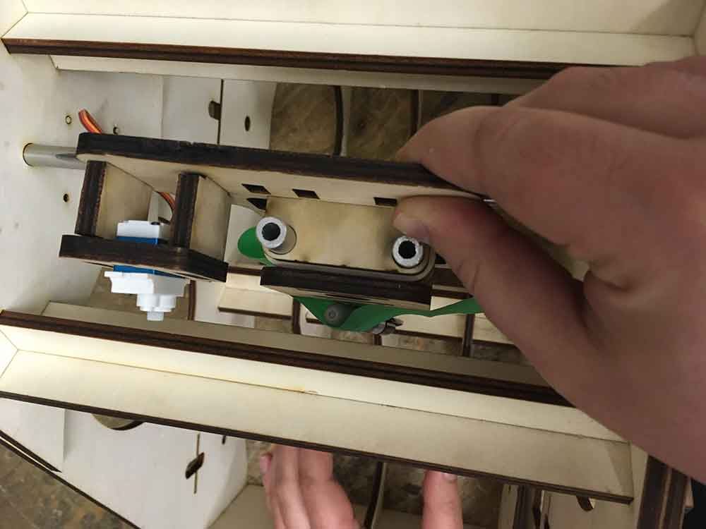
The feed mechanism is made by gluing a series of circles together. We ended up making two wheels for a balanced look as well as the help maintain grip even if the paper drifts.
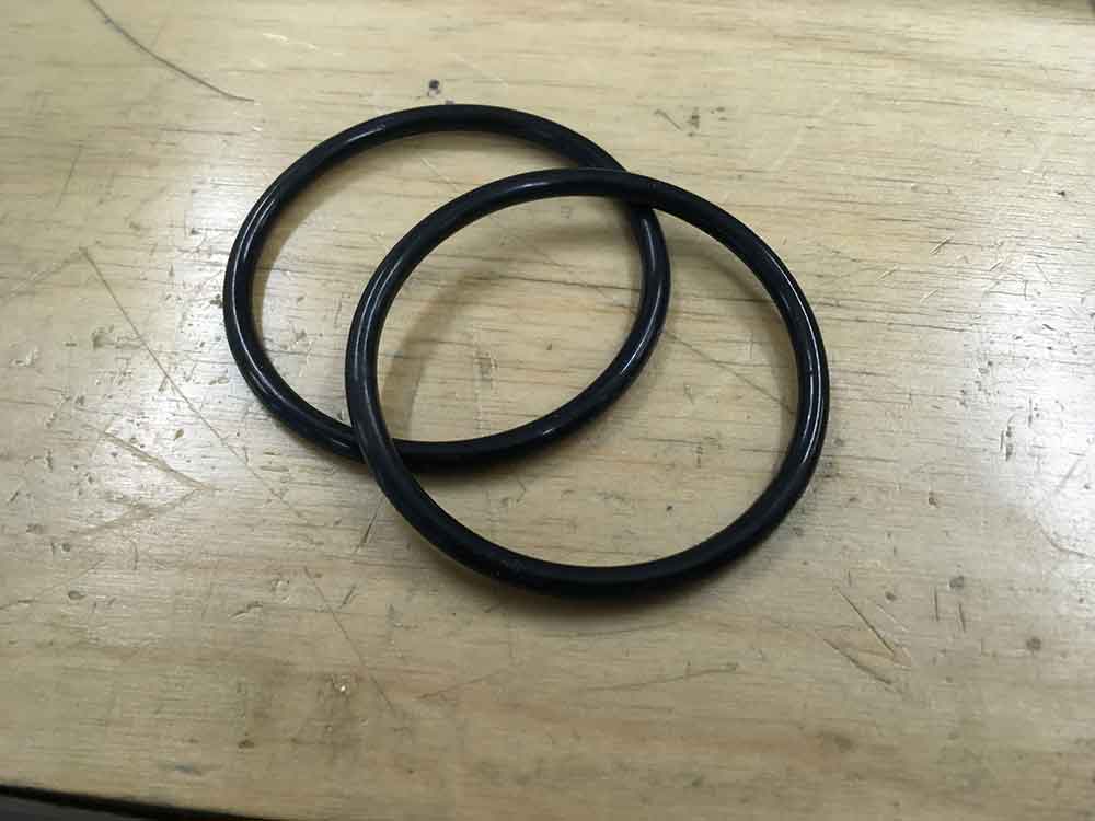
I had access to a bunch of 2.5" diameter "O-rings" which were pretty grippy. They are 1/8" thick and can stretch just enough to fit over our circles but it took some muscle. Marc did the measurements and glued the first set together. He calculated the perfect size of ring needed so that the bands would fit around the smaller circles and leave just enough rubber to provide grip for the paper. In total, there are 7 circles/wheel.
---> 4 x 92mm
---> 3 x 90mm
---> 6 x O-rings
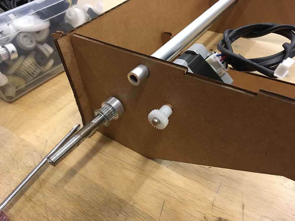
It was important that the wheels sit firmly on the linear shaft. The holes I had made initially were way to tight. Marc did some necessary tests and we ended up woth a 7.9 mm hole for the shaft. It was tight enough to be a bit of a struggle to get on but still manageable.

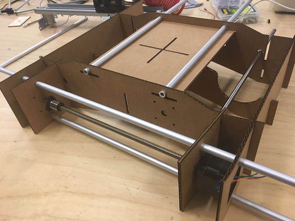
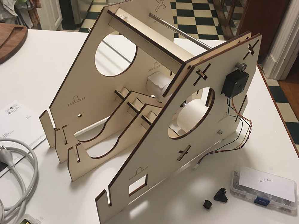
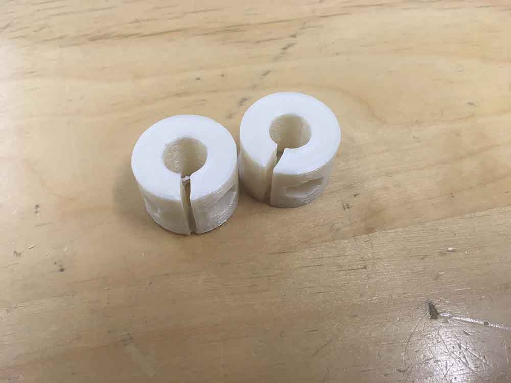
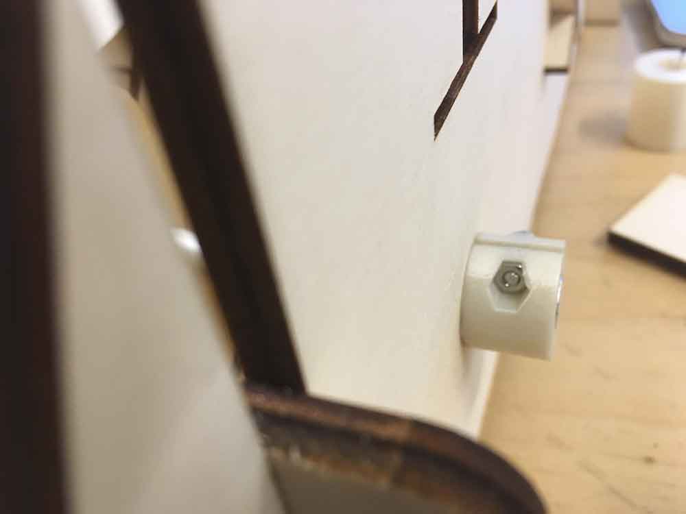
I made a couple 3d printed stops to prevent the rods from slipping off the frame. I also made a set to fit around the roll of paper. Helping to secure it to the rod. This was important to help keep the paper straight.
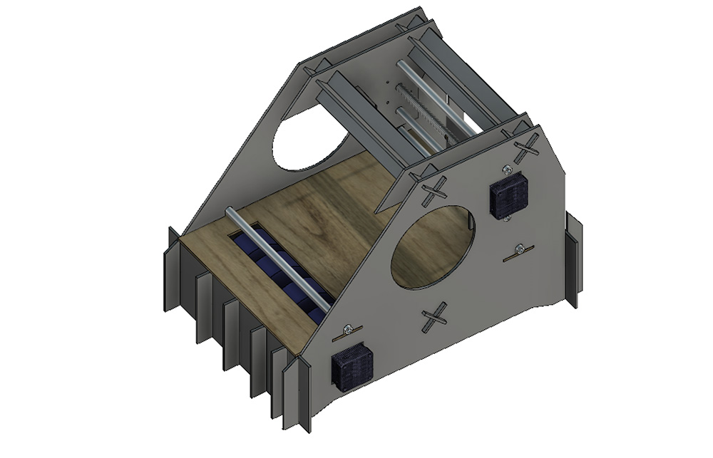
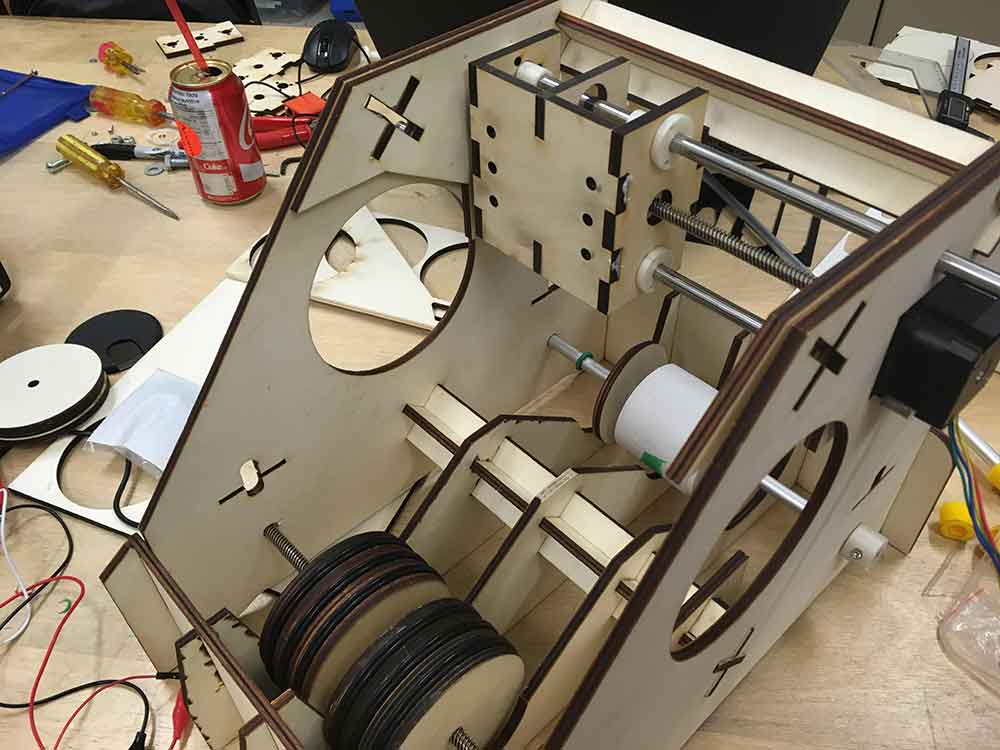
The final prototype worked out very well. The only issue was there not being enough space for George's x stage and the effector. We had to removed a set of cross braces but the machine was still plenty solid without it.
A view of the final assembly with Georges x-stage.
ASSIGNMENT FILES
---> GAM_Machine_Final.f3z
---> GAM_Machine_v3.f3z
---> AM_GAM_MachineCutFile.svg

This work is licensed under a Creative Commons Attribution-NonCommercial-ShareAlike 4.0 International License.