Input Devices
Task Requirments:
- Describe your design and fabrication process using words/images/screenshots.
- Explain the programming process/es you used and how the microcontroller datasheet helped you.
- Describe problems and how you fixed them
- Include original design files and code
Idea:
The Idea is to make a through beam "laser trap" counting sensor that i can use in my Final profect for counting caps.
I will use a laser Diode with a phototransistor sensor on the other side and record the difference in readings of the phototransistor when caps pass through.
I will use the Hello light 45 and will add two pin head to attach the laser diode to it.
Bill of materials:
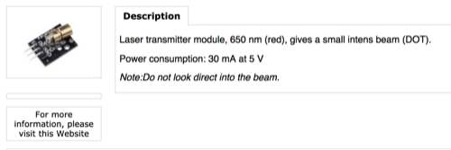
- Laser Diode module
- Attiny 45
- Phototransistor
- 2 R 10kohm
- 1 capacacitor 1uf
- 2 AvrISP pin head
- 1 FTDI pin header
Checking the current of the sensor:
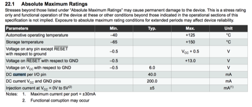
First thing i wanted to make sure that the Attiny45 can handle the current drawn by the laser diode module, so i checked the power consumption of the sensor on the selling website and it stated 30mA.
I searched the MCU data sheet and found maximum rated current 40mA
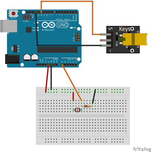
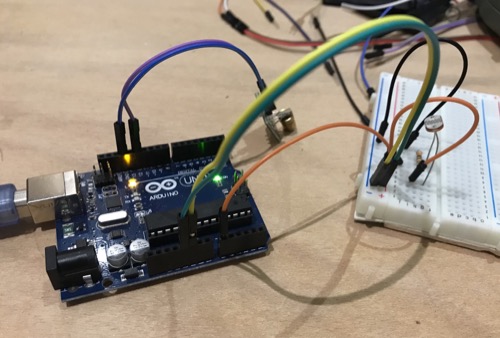
Testing the Idea on arduino:
I baught the Laser Diode module and found it with three pins one labeled GND and one labeled S for signal and the middle on with no label, I connected the module to the arduino to test it and it was working with just the signal and ground, i also googleed it and found this instructable that states that the middle pin is refrence where you can read the input voltage. I also connected a photoresistor to test the code.
	const int analogPin = A0;    // pin that the sensor is attached to
const int laser = 12;       // pin that the laser is attached to
const int threshold = 600;   // an arbitrary threshold level that's in the range of the analog input

void setup() {
  // initialize the laser pin as an output:
  pinMode(laser, OUTPUT);
  // initialize serial communications:
  Serial.begin(9600);
}

void loop() {
  // read the value of the potentiometer:
  int analogValue = analogRead(analogPin);

  // if the analog value is high enough, turn on the LED:
  if (analogValue < threshold) {
    digitalWrite(laser, HIGH);
  } else {
    digitalWrite(laser, LOW);
  }

  // print the analog value:
  Serial.println(analogValue);
  delay(1000);             // delay in between reads for stability
}
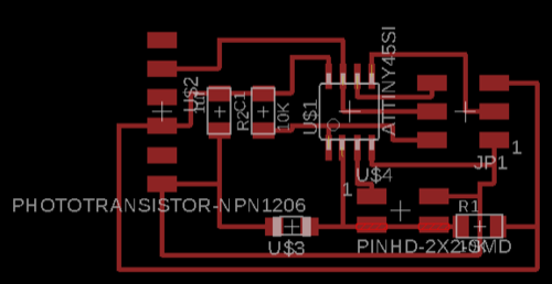
Designing The Board on Eagle
I added all my components to the schematic
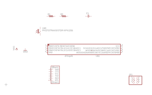
Through the net command i made a connection to each leg and connected them through names
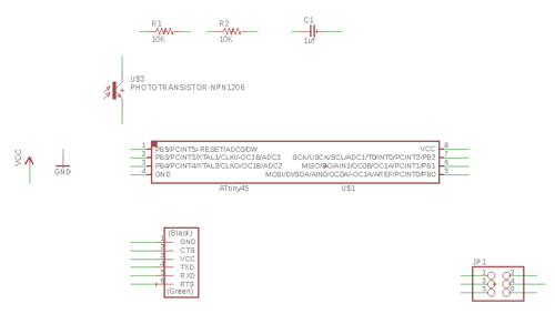
In the board view i arranged the components and routed the traces between them.
Finally i did a design rule check using DRC file of FAB.
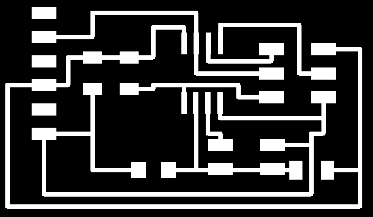
Then I exported the top layer as monochrome PNG and imported it to GIMP to make the traces and interior PNG
For detailed step by step for eagle design, refer back to Electronics Design.
N.B. For the laser diode connection, i couldn't find 1X2 pin headers SMD in the FAB library, so i used 2X2 and ignored the 2 pads in the routing and in the DRC.
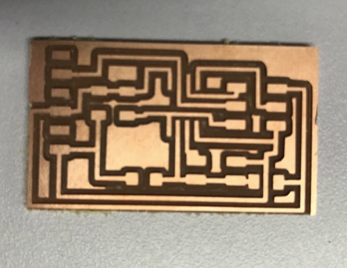
Milling the board on Modella MDX-20A
I imported the 2 png files to the fabmodules and milled/cutted the board using Modella MDX-20A.
For detailed step by step for board milling, refer back to Electronics Production.
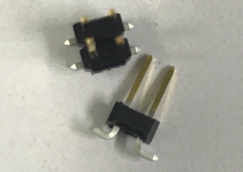
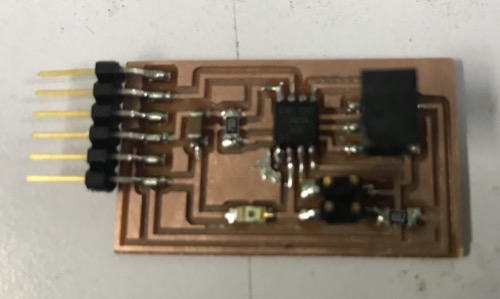
Soldering
I couldn't find the 2X2 Pin header in the lab inventory, so i had to break the 2X3 AVRISP to be 2X2
Before soldering the Phototransistor i had to check the data sheet to know it's polarity.
![]()
I soldered all the components to the board.
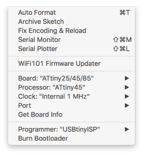
Programming
Using Arduino IDE, from the tools tab, i choose my processor: Attiny45 and the 1MHz internal clock
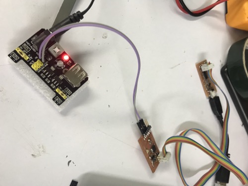
I burnt the bootloader using the fabisp while powering the board with external power supply as i didn't have FTDI cable.
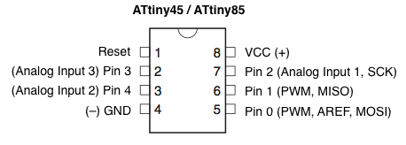
I searched Attiny45 arduino pinout to be able to define my pins my in code.
I tried to upload the same code i did upload on the arduino, but it failed to even compile
I figured out that this is because my board is missing the hardware natively built in the arduino "UART".
I googled "serial println for attiny45" and i found this useful tutorial on how to use software serial library natively installed on arduino IDE to substitue the hardware serial.
I copied the software serial code from the tutorial, added it to my code.
I defined the TX to the RX pin on my board "pin2", this is a very tricky part, the TX in the code is the RX on the board and vice versa.
I uploaded the code and it was uploaded succssefully
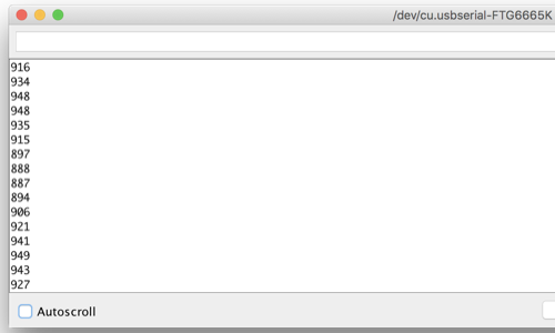
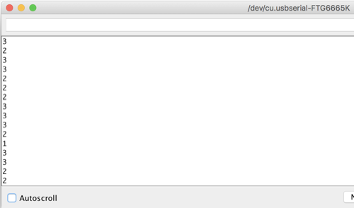
I connected the board to the computer with FTDI cable and started testing.
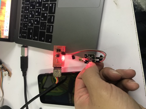
My sensor was reading a value of almost 900 with the ambient light, and a value of almost 0 when the laser is pointing at it.