Tasks:
- Design and build a wired and/or wireless network connecting at least two processors
- Implement and interpret networking protocols
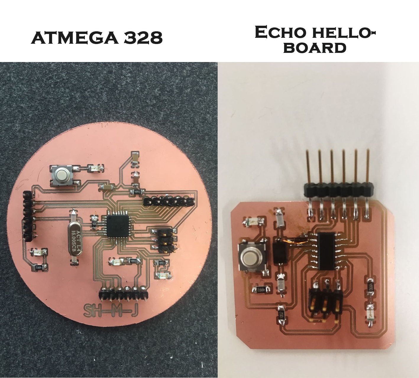
echo-hello board dose not have the serial communication hardware,ATMEGA 328 we have serial communication hardware and software.But unfortunately
In my board I broke the RX pin while I`m soldering the chip.
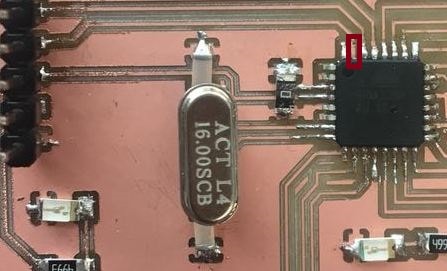
To Solve this problem :
First I used echo-hello borad as a master to program the Arduino board. I used software seial library.
     #include <SoftwareSerial.h>
SoftwareSerial A44 (0,1);  //RX and TX pins
void setup() {
  // put your setup code here, to run once:
A44.begin(9600); //start the software serial at 9600
}

void loop() {
A44.println(1);
delay (5000);

       }
Then to solve the problem of the RX pin in the Arduino board,I define it using software serial on a .
a general purpose input/output pin
      #include <SoftwareSerial.h> //include library

SoftwareSerial shmj(6,7);  //RX and TX pins
 int x = 10;
void setup() {
  // put your setup code here, to run once:
shmj .begin(9600);//start the software serial at 9600
pinMode (x,1); // led pin is output
}

void loop() {
  // put your main code here, to run repeatedly:
if (shmj.available ()>0) {
   digitalWrite(x , HIGH);
  delay(1000);
  digitalWrite(x , LOW);
  delay(1000);
}

}
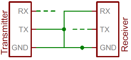
After I upload the code to the master and slave board, I made the connection between them. receives the message from the echo-hello board.
AT
OK
AT+CWLAP
+CWLAP:(0,"ZAIN-ZINC",-73,"70:3a:0e:d9:04:80",1,-7,0)
+CWLAP:(3,"Luminus Incepto",-76,"d4:2c:44:dd:4b:a0",6,0,0)
+CWLAP:(3,"Luminus_Guests",-77,"94:d4:69:f5:14:61",6,1,0)
+CWLAP:(3,"QUDS_LC",-77,"d4:2c:44:dd:3f:60",6,-9,0)
+CWLAP:(3,"Luminus Incepto",-73,"d4:2c:44:dd:54:e0",11,1,0)
+CWLAP:(3,"Luminus_Guests",-77,"d4:2c:44:dd:54:e1",11,1,0)
+CWLAP:(0,"ZAIN-ZINC",-77,"70:3a:0e:d9:0d:e0",11,-12,0)
OK
AT+CWJAP="Luminus Incepto","49380761"
WIFI CONNECTED
WIFI GOT IP
OK
AT+CIPSTA?
+CIPSTA:ip:"192.168.9.197"
+CIPSTA:gateway:"192.168.9.2"
+CIPSTA:netmask:"255.255.255.0"
OK
AT+CWMODE=2
OK
WIFI DISCONNECT
AT+CWSAP?
+CWSAP:"AI-THINKER_4289FA","",1,0,4,0
OK
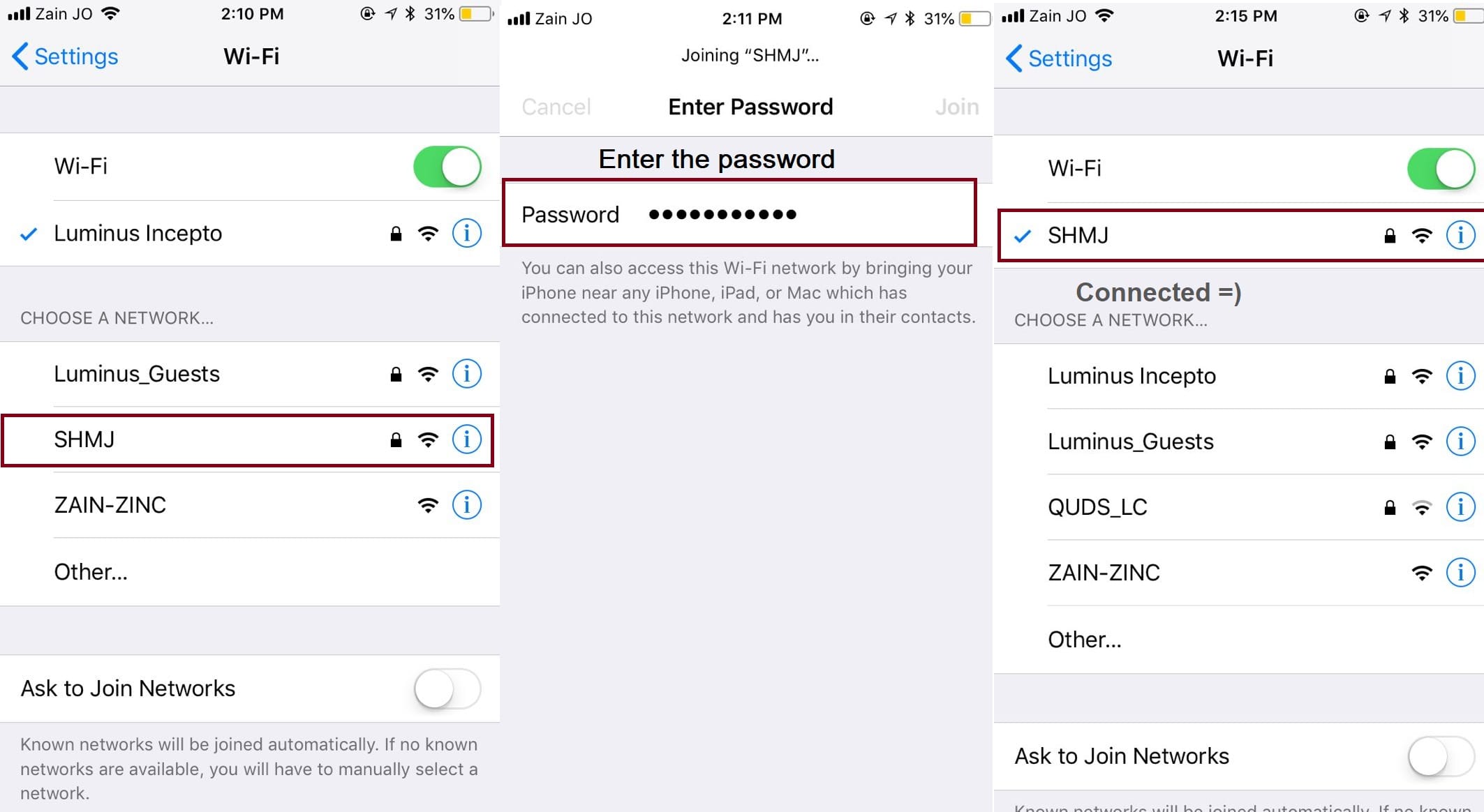
AT+CWSAP="SHMJ","shmj251993",5,3
OK
This is my screenshots 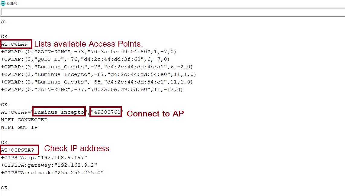
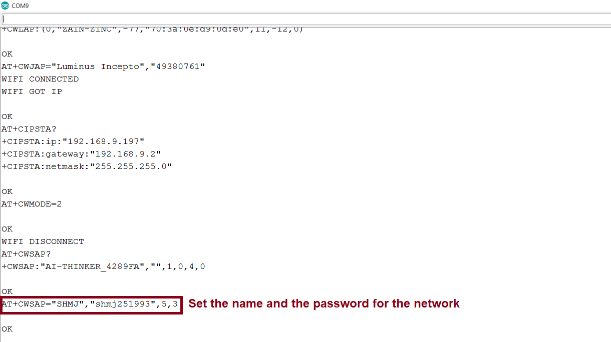
is connected to the network, it is called SHMJ