


Computer-Controlled Cutting
As above title of this week suggests, it is all about Laser and Vinyl cutting. From this week our fab academy is going much and more interesting. This week is full of learning environment, learning and working with different CAD softwares like, SolidWorks, InkScape, and Rhinoceros 3D. And, working with machines like 'Epilog Laser cutting Machine' and 'Vinyl cutter machine'.
- Group Assignment
- Characterizing lasercutter, making test part(s) that vary cutting settings and dimensions
- Individual Assignment
- Cut something on the vinylcutter
- Design, lasercut, and document a parametric press-fit construction kit
- Accounting for the lasercutter kerf, which can be assembled in multiple ways
Assigned tasks:
There are two assignments of this week:
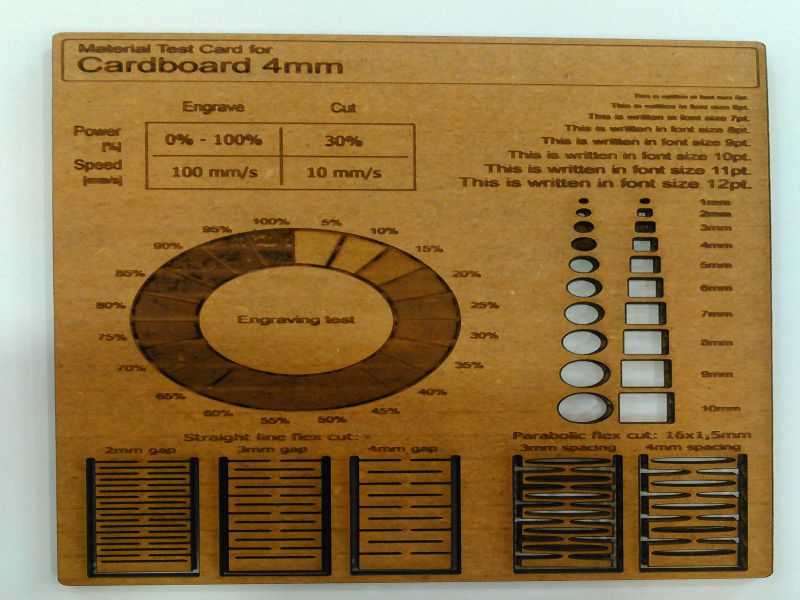
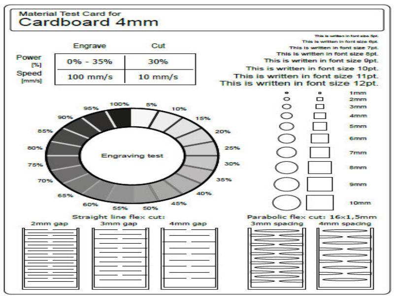
For group assignment, we are using a material test card which we found on Internet from Material Test Card for Laser Cutting and Engraving. This card is helpful to document the machine performance on any material. We are using 4mm cardboard to test machine parameters. In this test we are checking its engraving power, engraving performance on different font sizes, cutting accuracy by cutting different size shapes and, parabolic and straight line flexes by varying line spacing
Steps For Laser Cutting Machine
As per instructions we set cutting line strokes to 0.001 inches. Other vectors except 0.001 inches set to engrave with respect to their greyscale color. Then we convert our SVG file into PDF while setting page size to 32x20 inches from document properties and selecting 600 dpi as resolution for rasterization
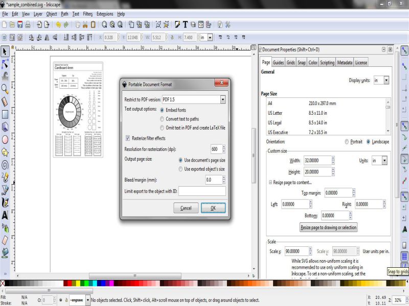
setting up file in svg and convert into pdf
Now we open PDF file and press Ctrl+P to open printing properties, Select "Epilog Engraver WinX64 Fusion" in Printer Tab and "click Properties"
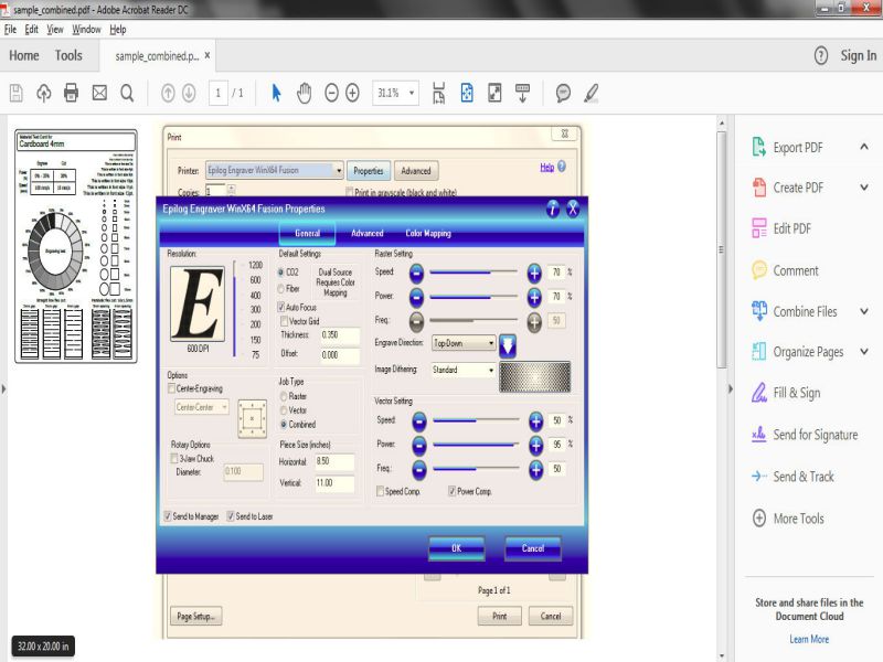
Raster/Vector power and speed settings
Click on combined in "Job Type". We set Raster power to 100% and speed to 100%. and Cutting power to 30% and speed to 10%, after setting up parameters click "OK" and the job transfer to Epilog Job Manager.
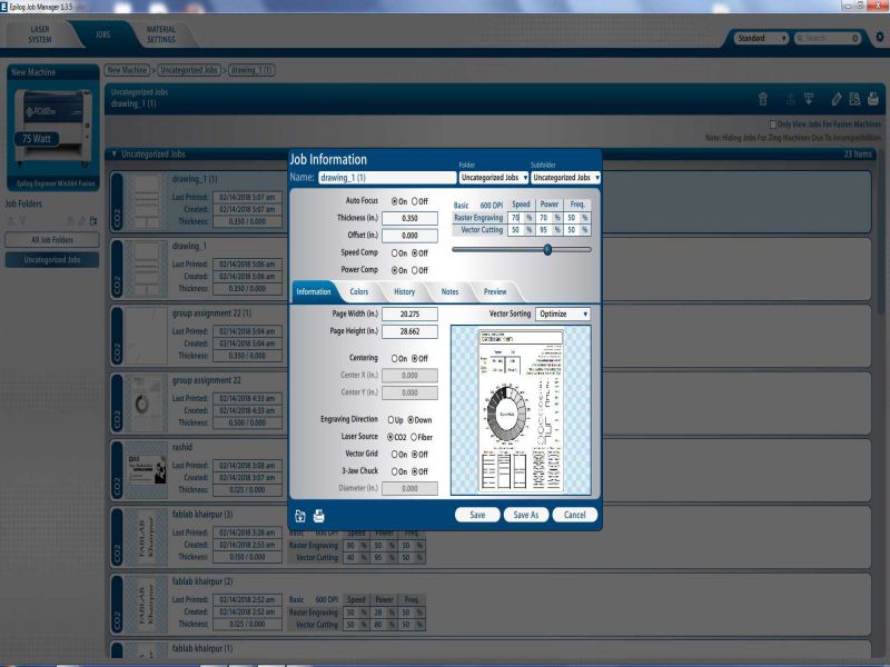
Job information in Epilog Job Manager
We select our job and check the preview by clicking on "preview".Select the location of job by dragging the image in preview menu and set where we need it on Laser machine bed, and click "Save"
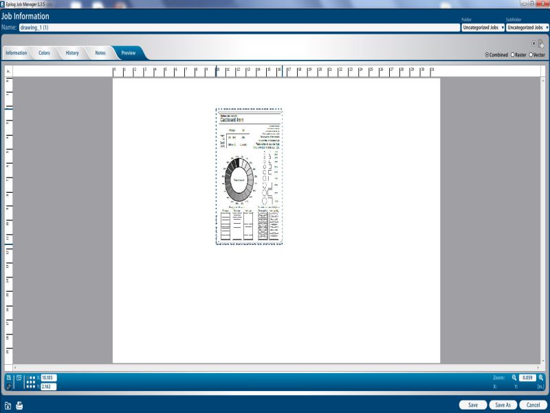
Job Preview Window
After selecting the location click Save and click on print to transfer job to laser cutting machine.

Display of job information on Laser Cutting Machine panel
Press "GO" on machine panel and leave rest of the work on machine.
Laser Cutting Machine while working on Job
The perfect End Result.
Final Product
Comparision
1. Vinyl cutter
A 'Vinyl cutter' is a computer controlled machine. This machine is controlled by a computer and operate similar to a printer. A vector based design is created in software program (I used InkScape) and then sent to the cutter where it cuts along the vector paths of the design. So, it doesn't work on bit map images, it works on vector based images or texts.
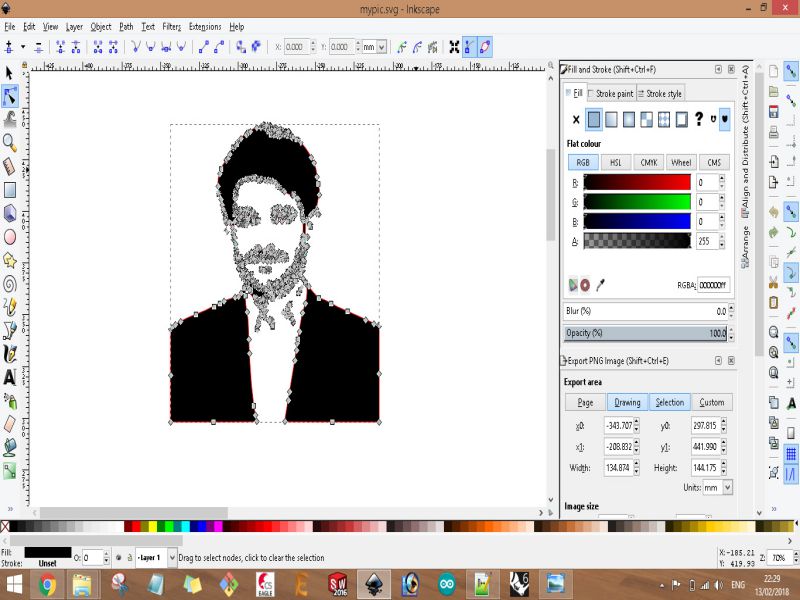
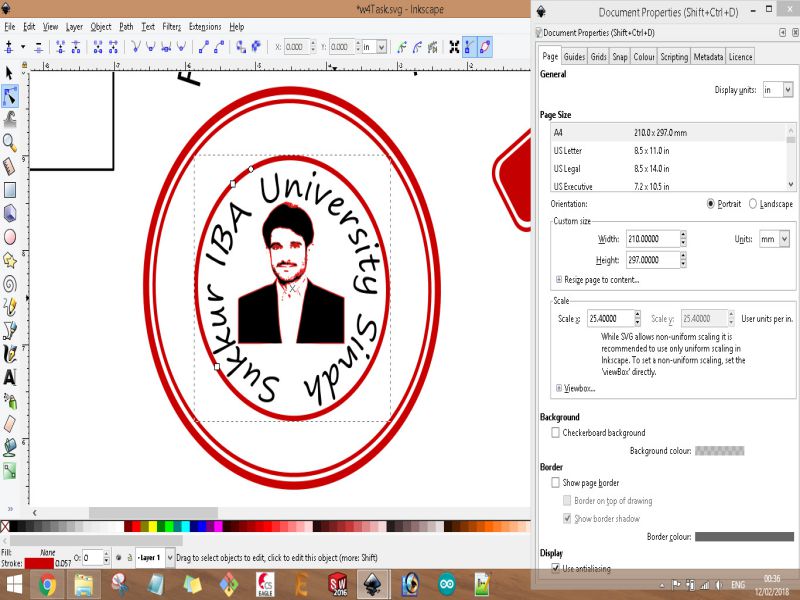
Steps of my designed project for Vinyl Cutter in InkScapeFor this task, I created a design combination of my image and texts. In beginning, I put my image then applied 'Bezier curve' function and 'edit path by node (F2)' function for removing the background of my image. After this I used 'Trace bitmap (Shift+Alt+B)' function to gray out the image. Now, I put my image in the circle and wrote text then used 'put on path' function to change texts as circle, again i repeat this for another layer of words then cut down the two circles. And, also played few other functions to beautify my design.
Design process images are give below:


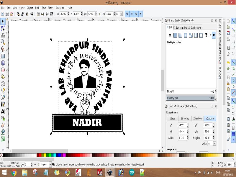
Once designed was complete, I export the design in 'png' format then converted it into 'jpeg'. I opened this image in Roland Cutter software 'Cut Studio' and proceed the further steps.

Steps of using Cut Studio
- Open the Cut Studio software in PC.
- Import JPEG file( or PNG).
- From right side panel set the dimension of imported image.
- Right click on the image and click on Image Outline.
- Now a window appear, from there click on Extract Contour then OK it.
- Now we have Contour of the image, and this is what a vinyl cutter needs
- till here, everything is done so, press Cutting tab.
The necessary thing is to set the position of the vinyl sheet in vinyl cutter. So, I am writing below its steps.
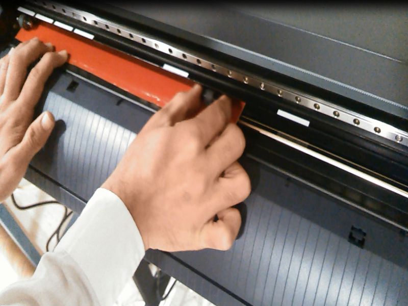
Steps of inserting Vinyl Sheet in Vinyl Cutter- Switch On the Vinyl Cutter machine.
- Press back the lock handle.
- Insert vinyl sheet in it, either in the form of piece or roll. I used a piece of vinyl sheet
- Align the sheet through wheel holders and one can also set it using white marked lines.
- Now, pull back the handle lock to lock the current position of the vinyl sheet.
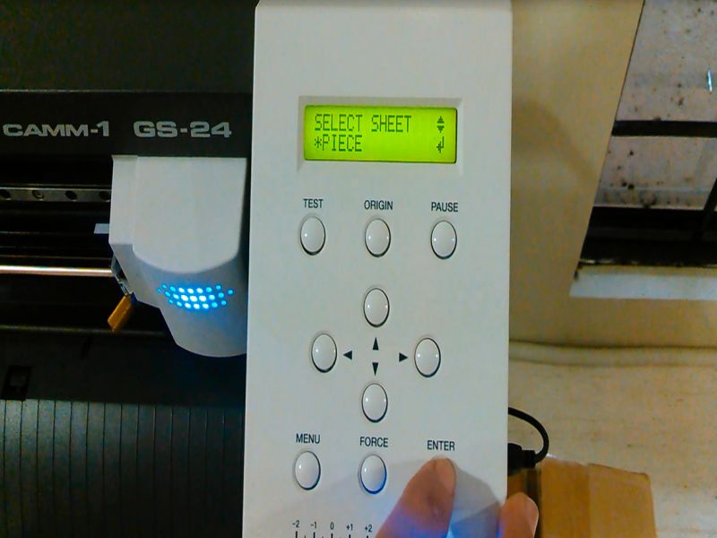
- Now, using operating interface of the vinyl cutter machine, select the sheet type (sheet or piece) then press 'ENTER' button. I used piece, because I set and fix a piece of vinyl sheet in it.
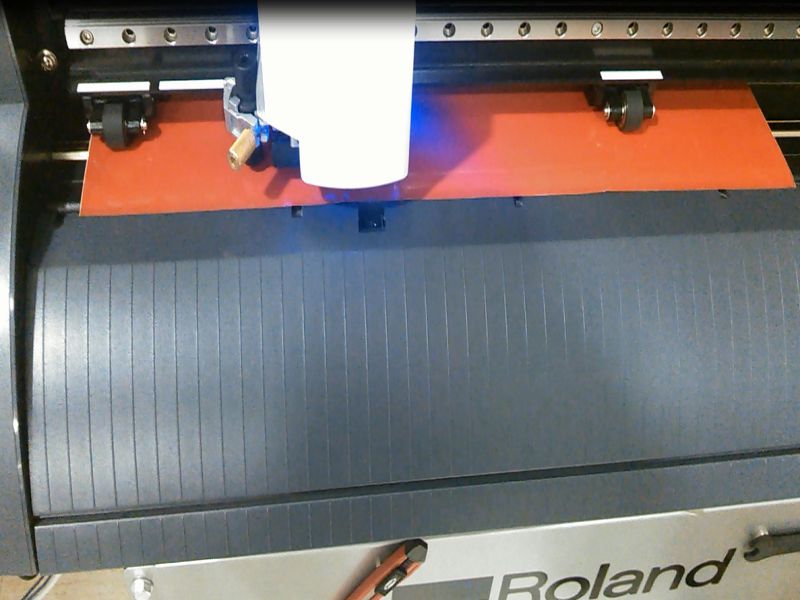
- Now, the cutting head moved and scanned the actual size and dimension of the inserted piece of vinyl sheet, and showed it on the screen of operating panel interface of the vinyl cutter machine.
- After all above steps, the machine is now drawing my design through its small pin.
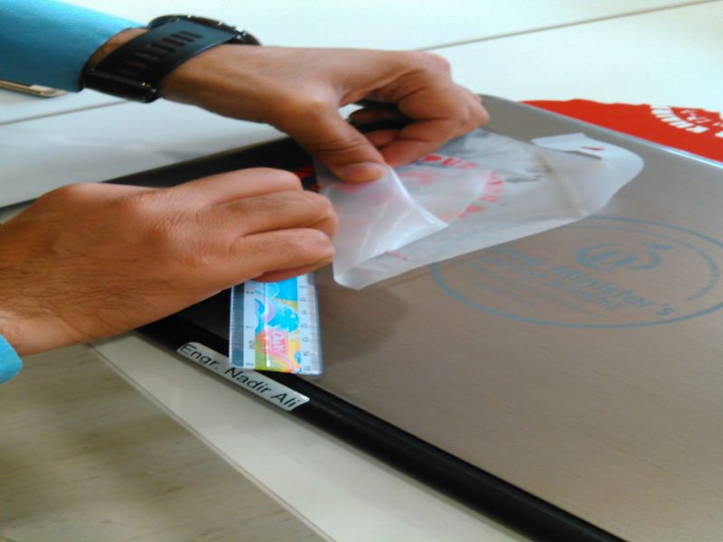
Vinyl cutter process images are given below:
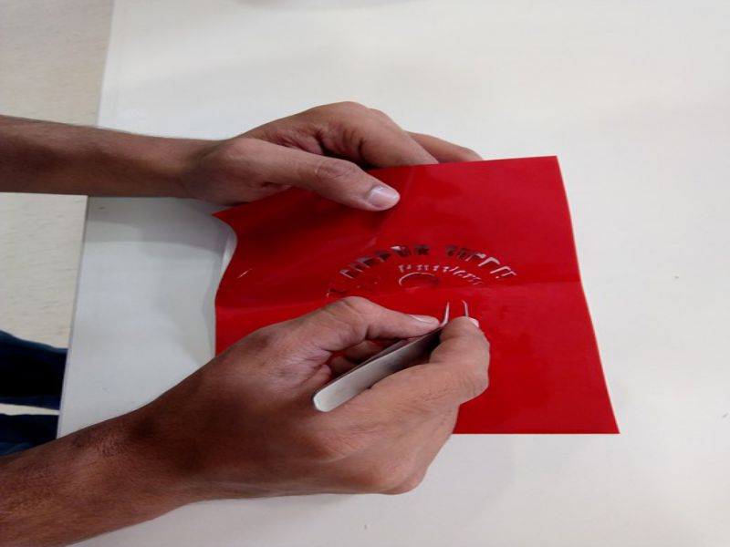
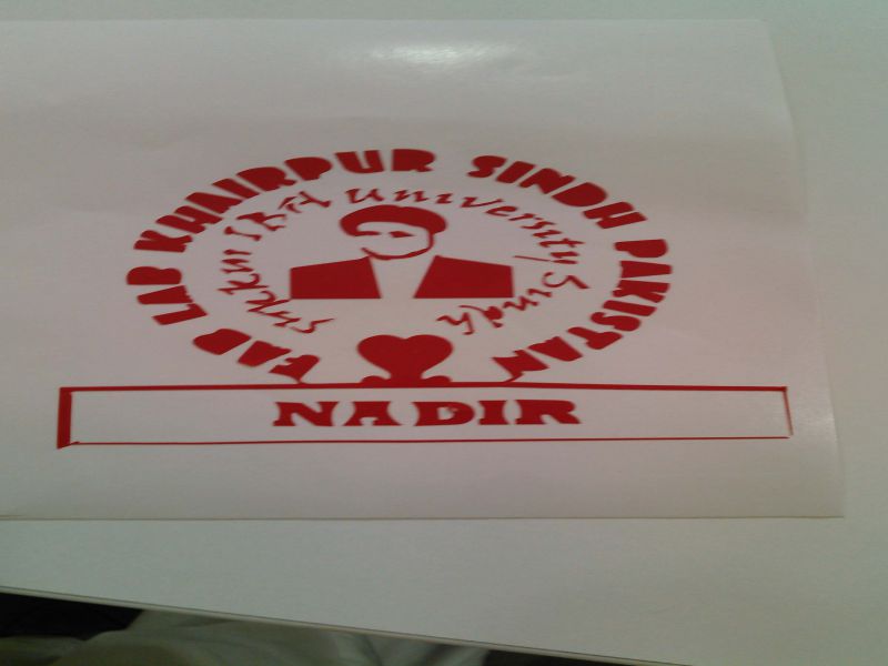
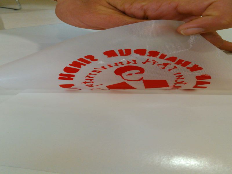
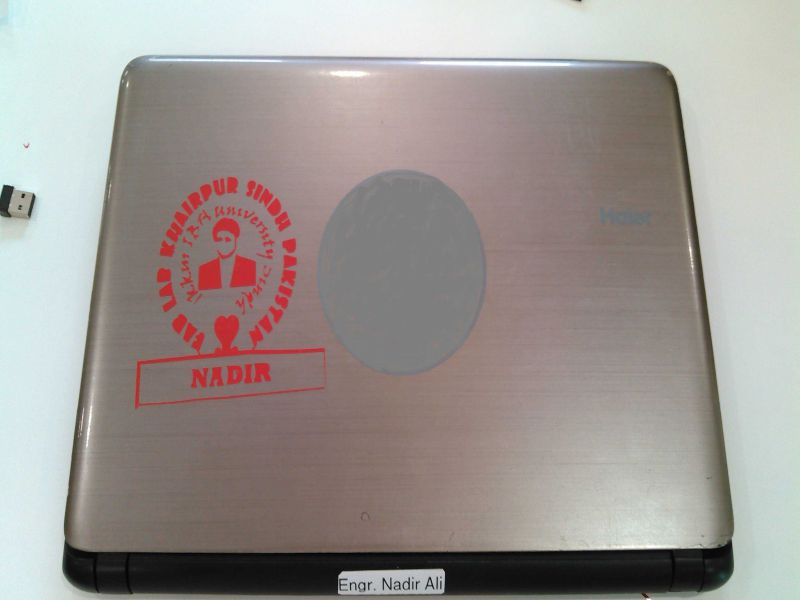
I also designed and cut few other stickers, I liked and enjoyed this process of sticker designing.
2. Laser cutting (press-fit construction based)
'Laser cutter' is a computer controlled machine and it uses a laser to cut the materials. In this week, for this machine, task was to construct a press fit product. For designing of this task, I used SolidWorks, Rhino 3D, and InkScape. I used different softwares because to finalize a software which I have to use for rest of assignments where needed. In last, I set my mind to work with SolidWorks, as it's a very powerful tool, no doubt Rhino is also good.
Press-Fit Construction is also known as friction-fit construction. There are few thumb of rules for press-fit construction kit:
- All the pieces of the designed product must fit together with little pressing their edges and joints
- Use of glue, screws, nails or any other fastener is not appreciated
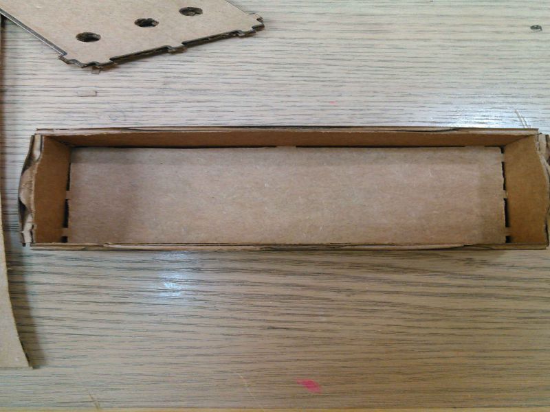
For this task, I designed a simple open box using 'SolidWorks'. Snaps are given below:
But, I did not laser cut it, because I did this only for practice.
Again, I wanted to design a simple pen container box. For this, I used 'Rhinoceros 3D' software, which is non-parametric, to make it parametric we have to use 'grasshopper' which is 'visual programming language'. I installed 'Rhino 6' on my laptop. Then I tried to design the box, below snaps show my first sketch.
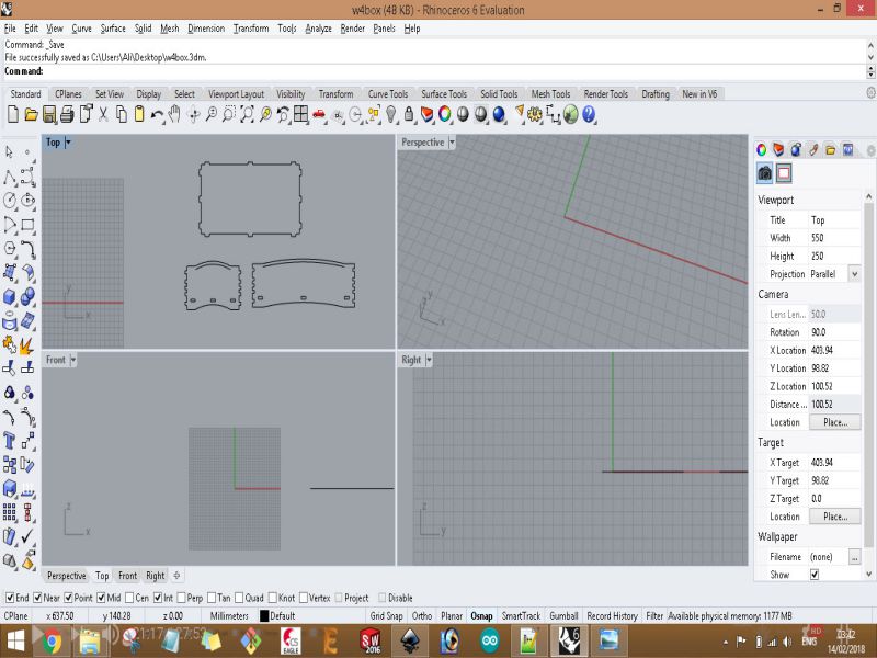

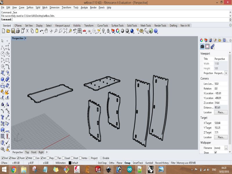
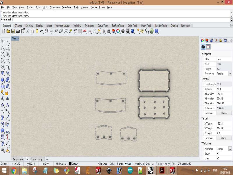
Connecting the pieces of the box
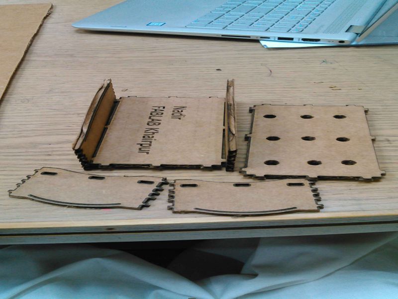
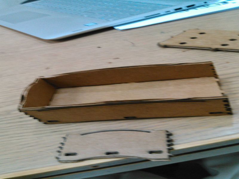
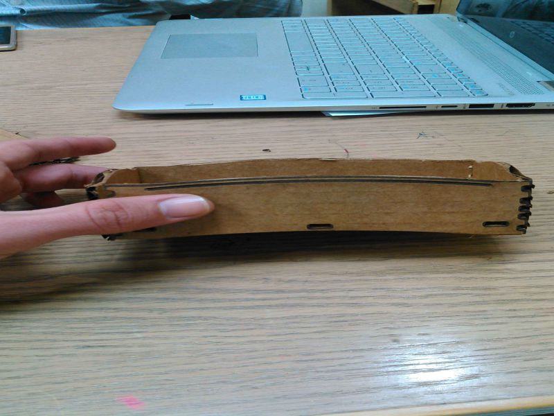
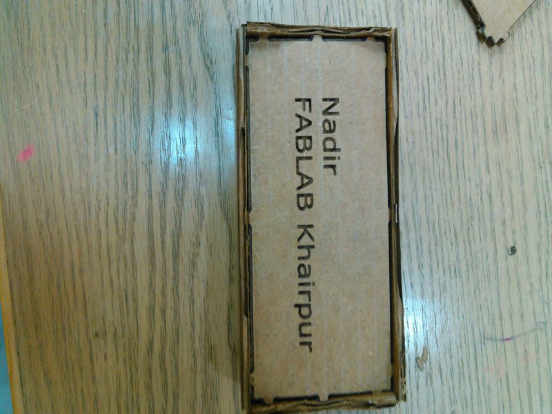
Bottom side of the box
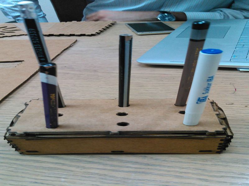
Pen and pencils in the box, but top side is not connected well
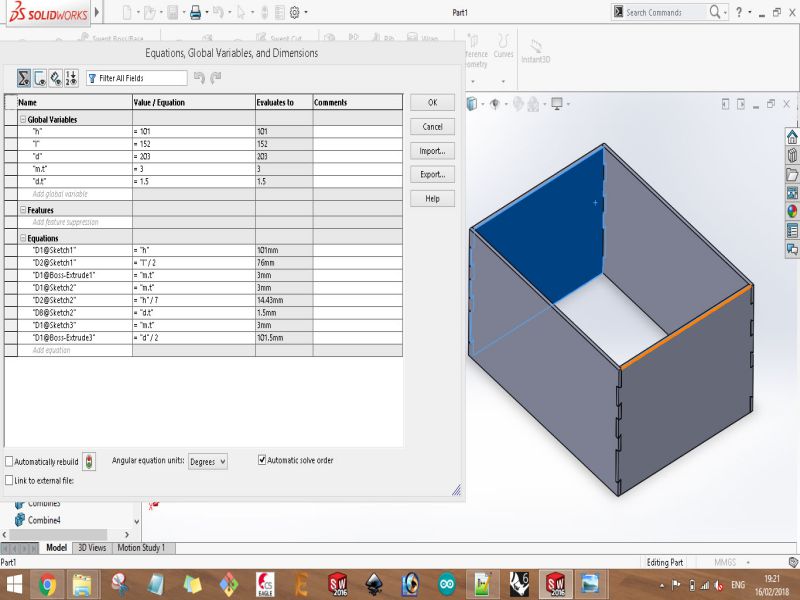
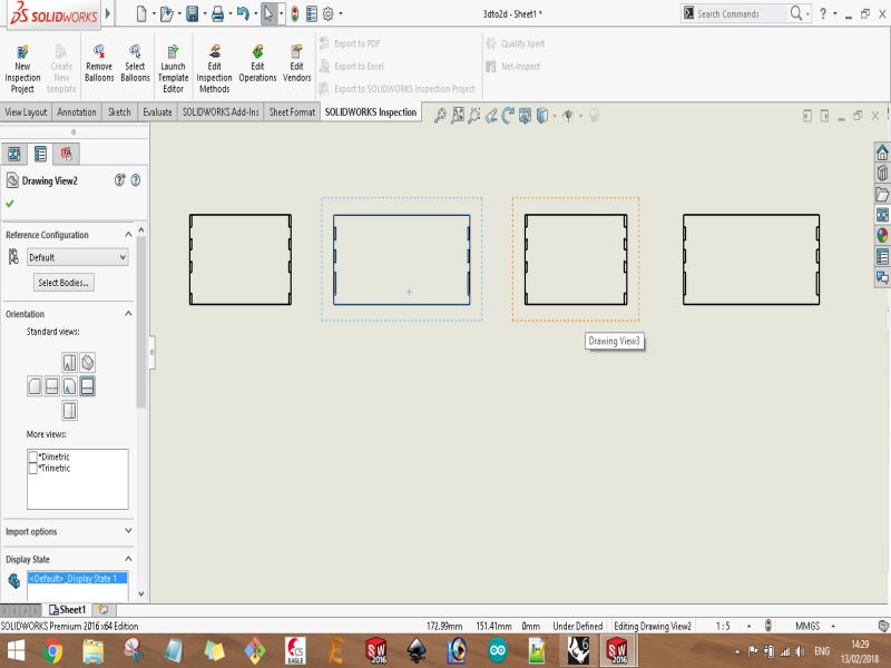
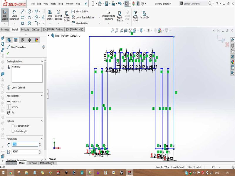
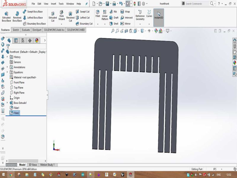
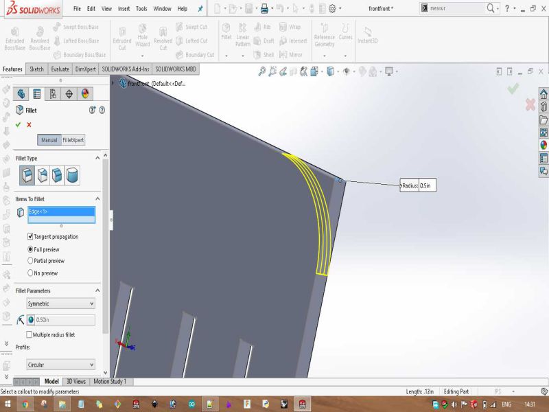
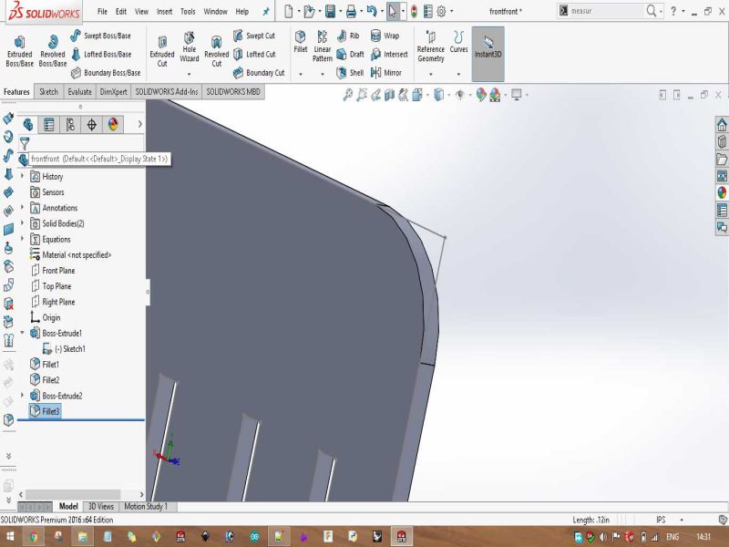
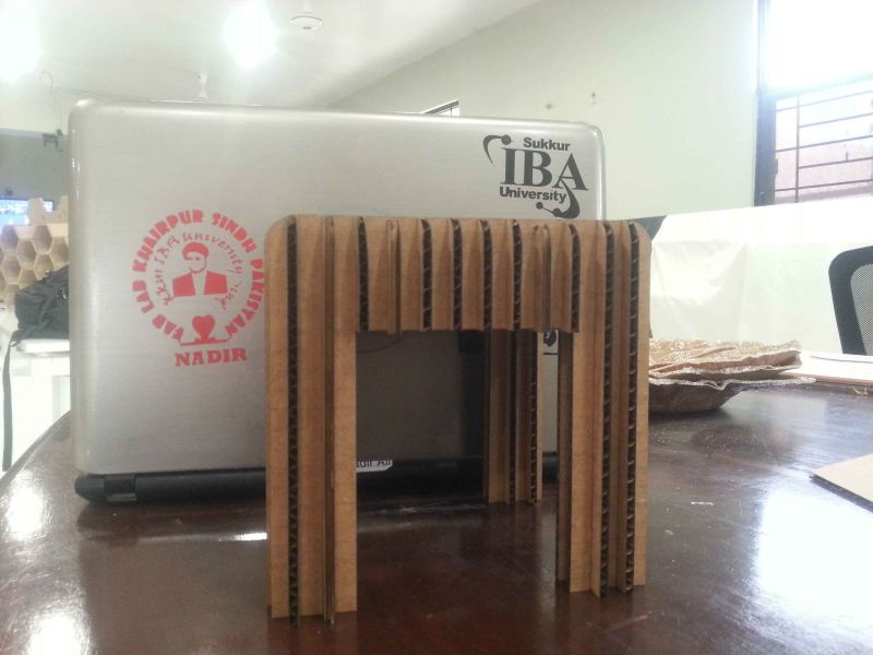
Parametric design using SolidWorks
After experiencing it, I can say that SolidWorks is the best parametric CAD software. For fulfilling the basic requirement of this task, we have to laser cut a model which must be designed parametrically in any parametric CAD software like SolidWorks or Fusion360. I choose to design my model in SolidWorks.
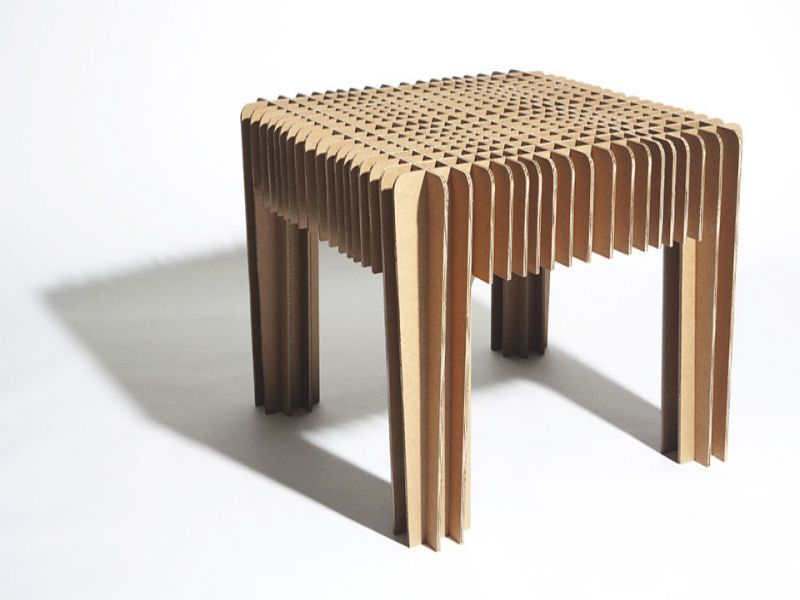
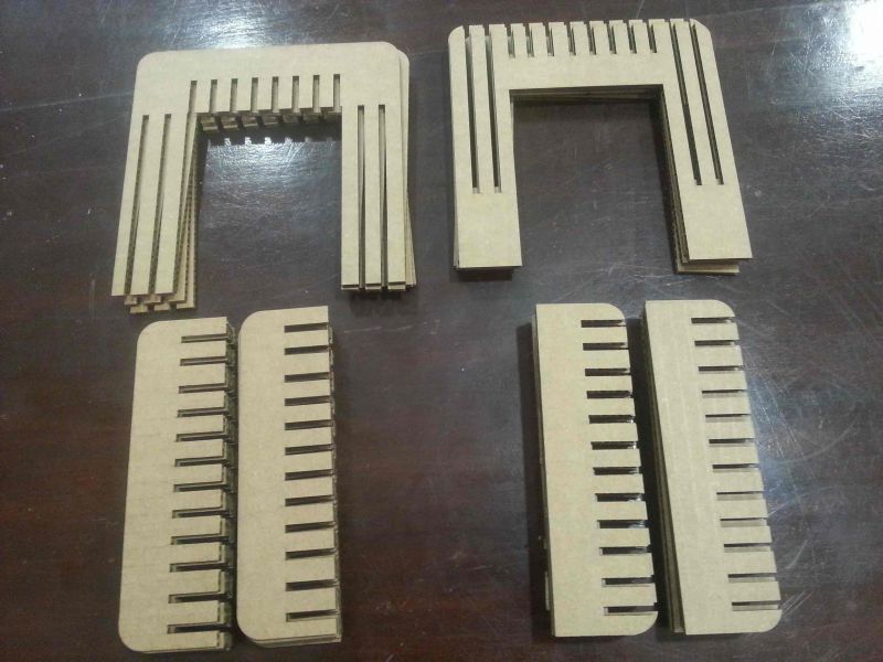
For this, I visited the laser cut models of David Graas. And, selected following design.
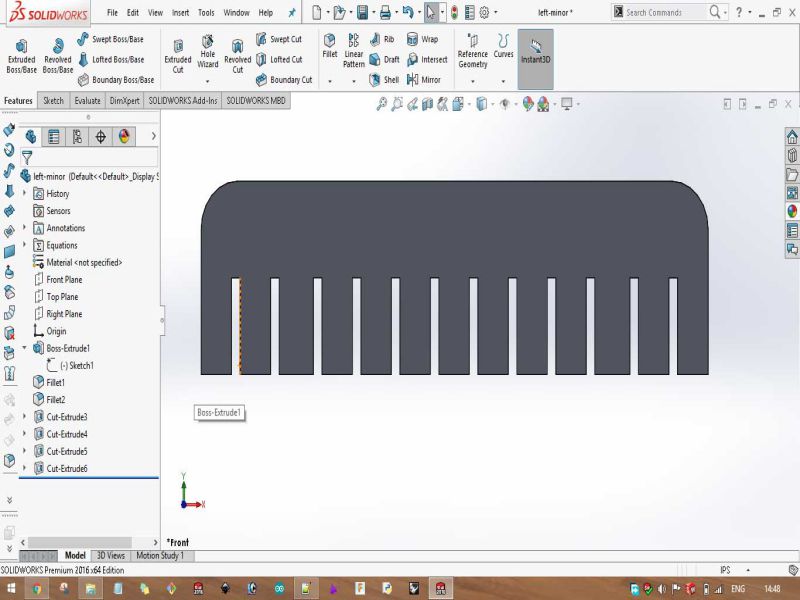
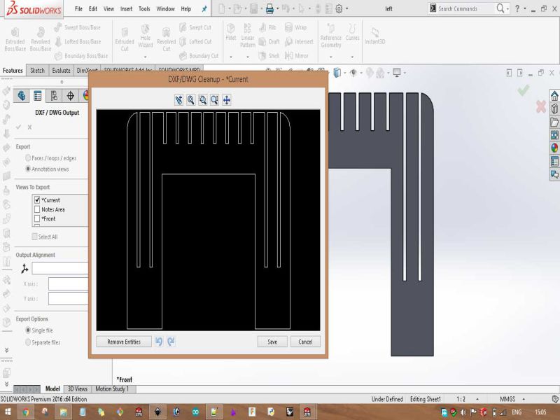
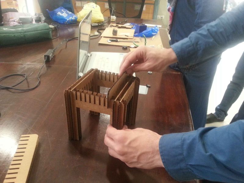
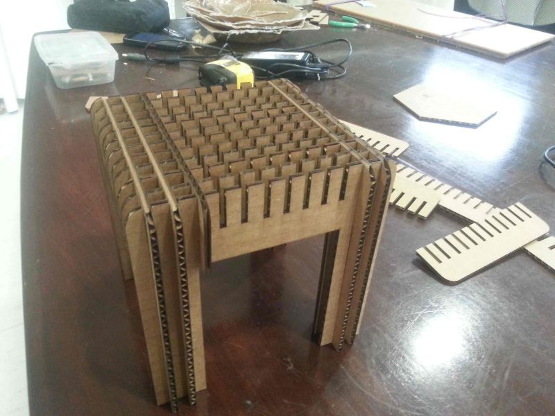
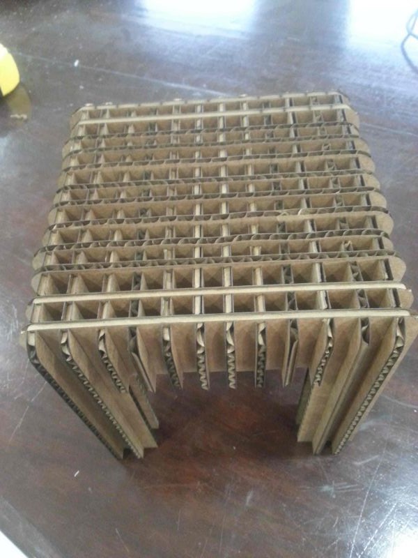
I started to design the model for myself, in SolidWorks. Few deigning process snaps are given below.
My designed parametric model's files can be download from Here.
Benefits observed by parametric design
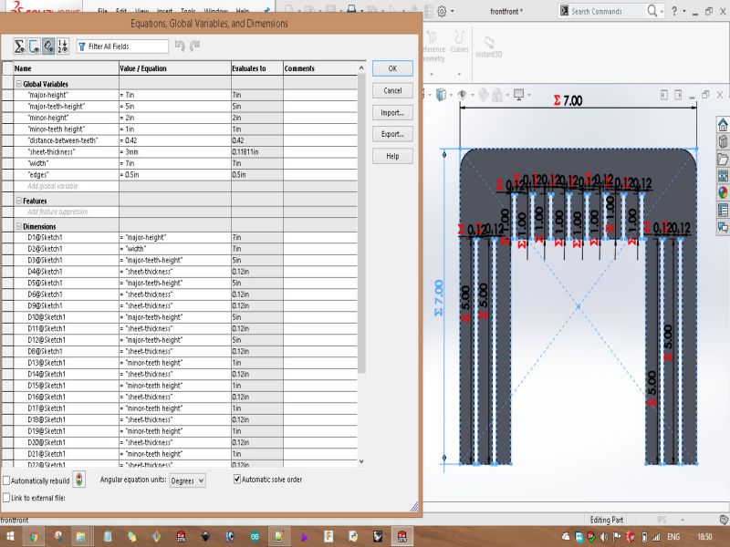
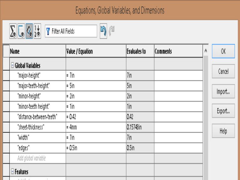
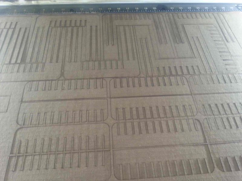
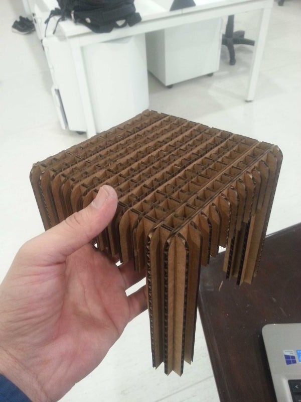
Parametric design reduces the problems which occurs when we think to change the design parameters. take the my example, I designed it in SolidWorks by setting "global variables" of the parameters of the design. I choose 3 mm (0.118 in), because I thought to laser cut it on plywood of 3mm thickness which is available in our lab. When I complete my whole design, then I recognized that we have few sheets of 3mm plywood in our lab, in other hand I saw that we have 4mm (0.157 in) cardboard in abundant quantity. So, I set my mind to laser cut my design on cardboard. Here design needs to change from 3mm of thickness to 4mm. What I did, I just went to "Equations" and change the thickness from 3mm to 4mm in "global variables". This way, every where the design changed its thickness, and where ever I used this parameter it changed accordingly.Learning outcomes and conclusion
- Leaned how to design your designs parametric using SolidWorks CAD software.
- Learned that how to run 'Vinyl cutter machine' and 'Epilog laser cut machine'.
- Laser cutting machine is the effective way to engrave and make designs on plywood, cardboard, and other materials too.
- Vinyl cutting is the effective method of making stickers.

This work is licensed under a Creative Commons Attribution-NonCommercial 4.0 International License.