

Success is a journey, not a destination
Individual Assignment:
- Add an output device to a microcontroller board you've designed, and program it to do something.
Group Assignment:
- Measure the power consumption of an output device.
Individual Task:
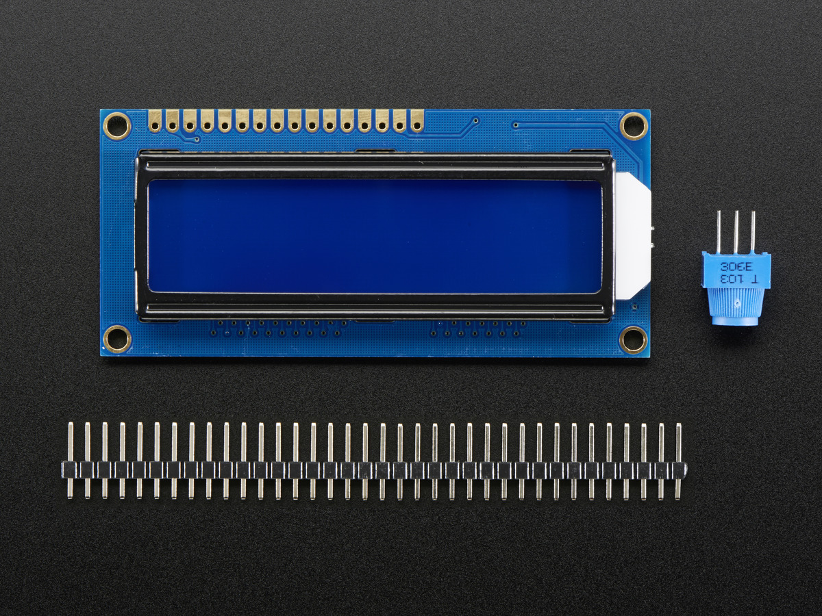
In the previous week, we designed and Input device and programmed it, while this week we are required to make an output device from the list provided in the class schedule and program it to do something.I decided to work on LED array through charlieplexing , but there were some issues in my design. Then, I was running short of time so, I decided to work on Standard LCD 16x2 + extras - white on blue. This is really an intresting module to work on. I read the pin description and other infromation from the link given HERE
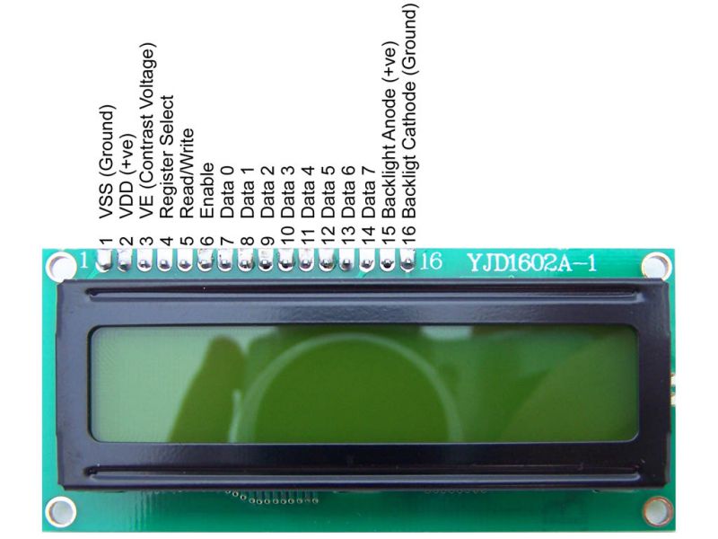
The following description has been taken from the link given above:
tandard HD44780 LCDs are useful for creating standalone projects.
- 16 characters wide, 2 rows
- White text on blue background
- Connection port is 0.1" pitch, single row for easy breadboarding and wiring
- Pins are documented on the back of the LCD to assist in wiring it up
- Single LED backlight included can be dimmed easily with a resistor or PWM and uses much less power than LCD with EL (electroluminescent) backlights
- Can be fully controlled with only 6 digital lines! (Any analog/digital pins can be used)
- Built in character set supports English/Japanese text, see the HD44780 datasheet for the full character set Up to 8 extra characters can be created for custom glyphs or 'foreign' language support
- Comes with necessary contrast potentiometer and strip of header
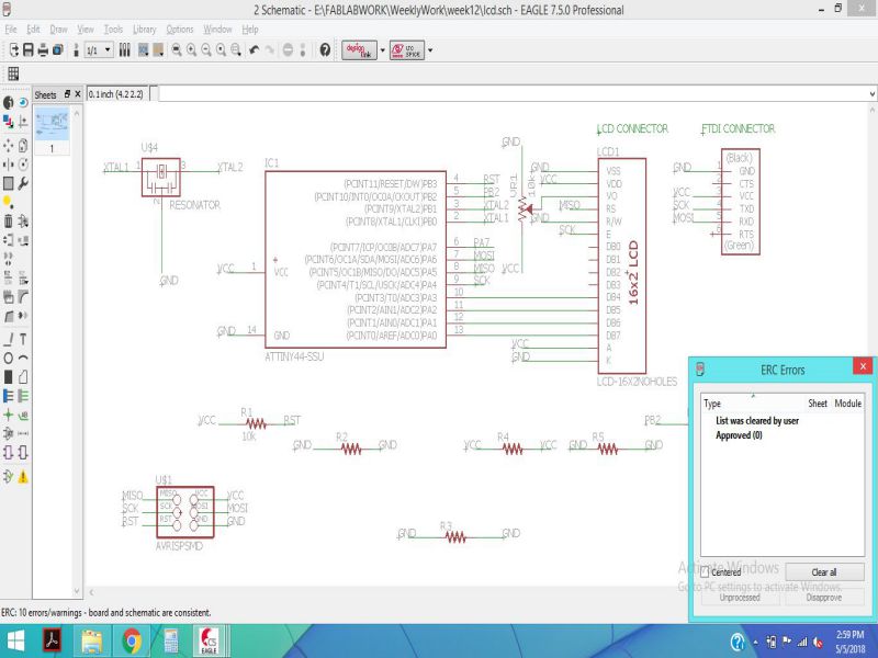
Making the Schematic on Eagle
In order to redesign the circuit, I used Eagle software. The schematic is shown below, along with the board. Following image shows the pin configuration used to make the connection between ATtiny44 and LCD.
The connections of ATitny44 and LCD are shown below:
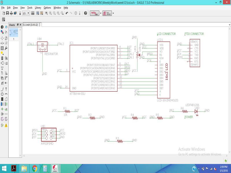
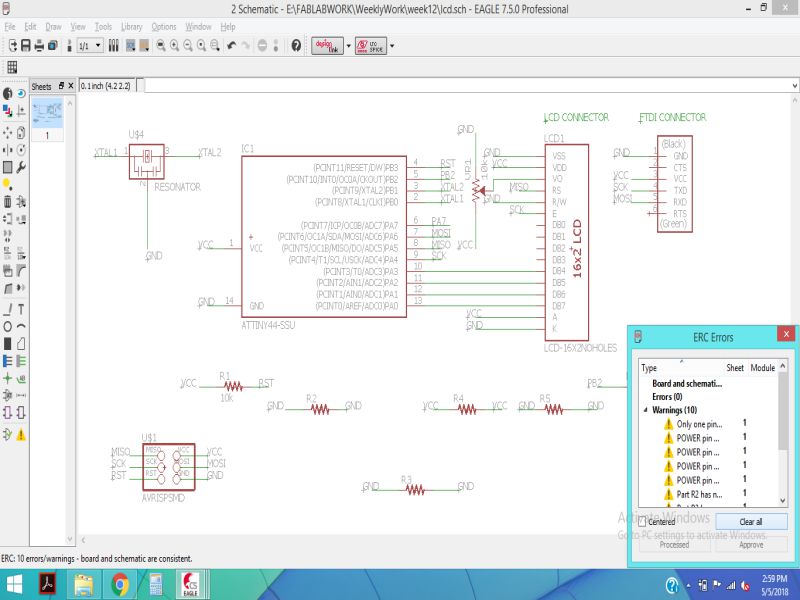
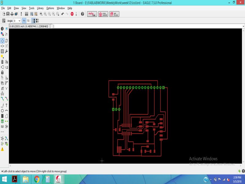
The schematic was checked for errors, and there were no errors .
Then, by clicking on switch to the board, I made the routing connections and exported the images for generating RMl files.
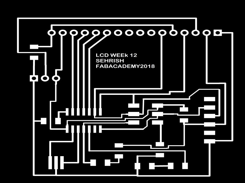
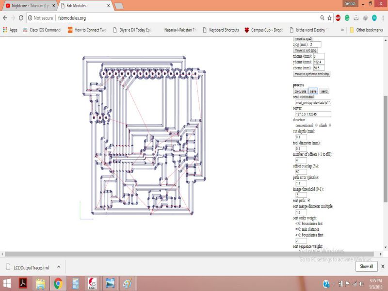
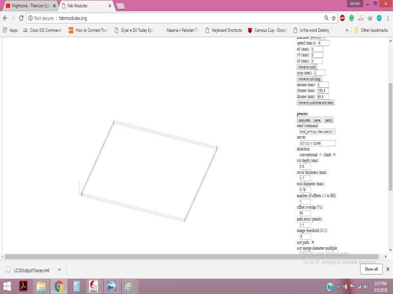
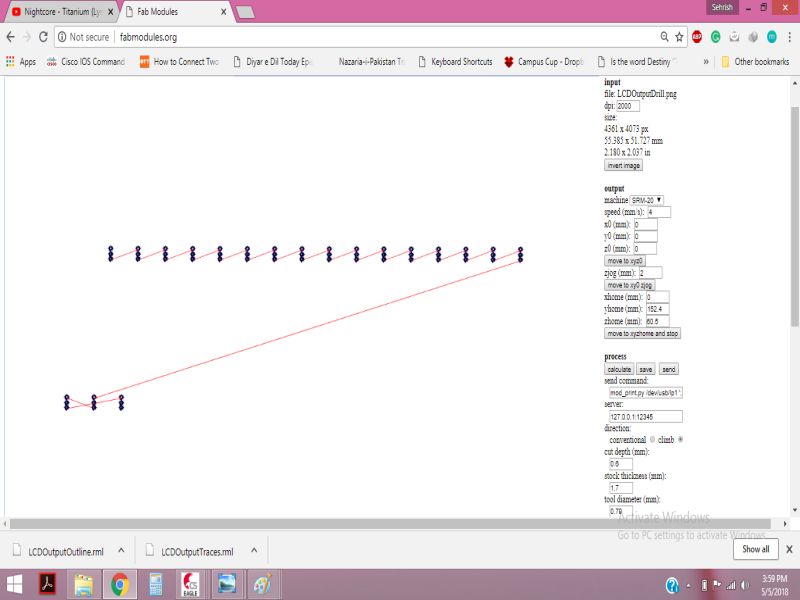
Milling the Board
For generating the RML files, I used the png images given below and edited them in paint.

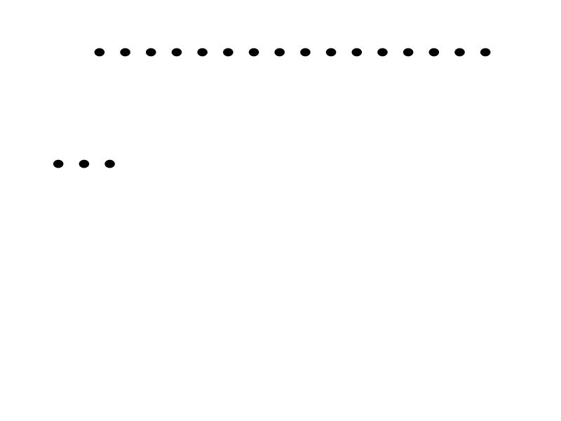
In the next step, I generated the RML files from fabmodules.org, as shown below:
Soldering the Components
After milling the board, its time to solder the components, the lit of components is given below:
- ATtiny44
- 20 MHz Resonator
- FTDI Connector
- 2 x3 ISP Header
- LEDs for power up and the other connected on 8th pin of IC
- potentiometer 10 kohm
- Connecter for LCD
- zero ohm resistor (as jumper)
The board after soldering the components is shown below:
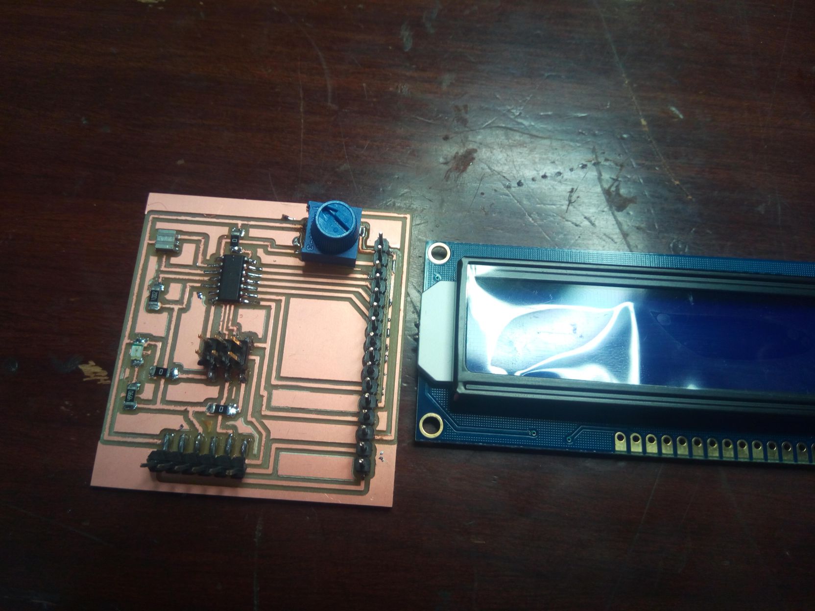
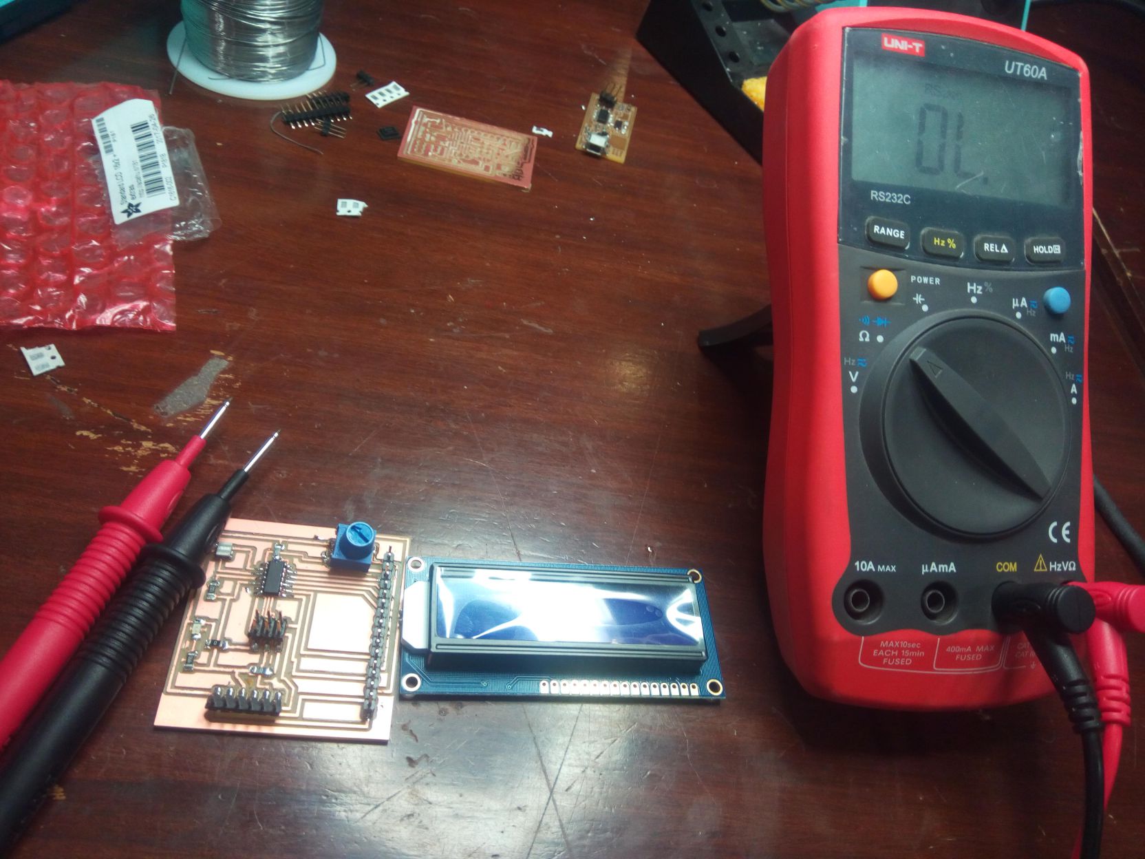
Then, I checked all the connections using DMM, so that I was sure that the board will work fine when programmed.
Programming the Board
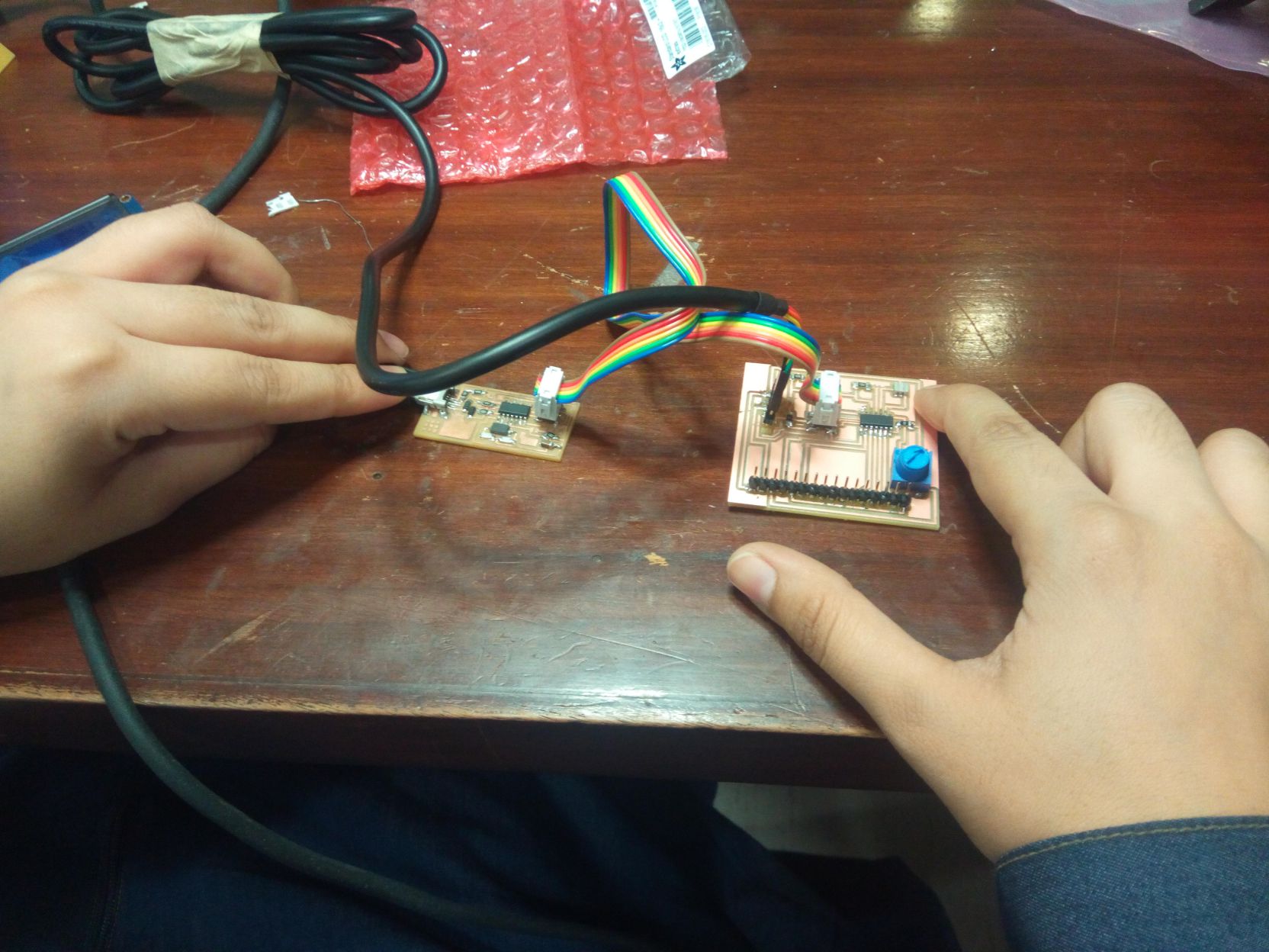
After making the necessary settings for ATTiny44 IC in the arduino IDE, the final step was to burn the bootloader and then upload the code to display something on the lcd. All the connections were fine except one connection, so I corrected that connection and burned the bootloader successfully .
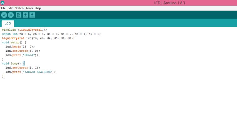
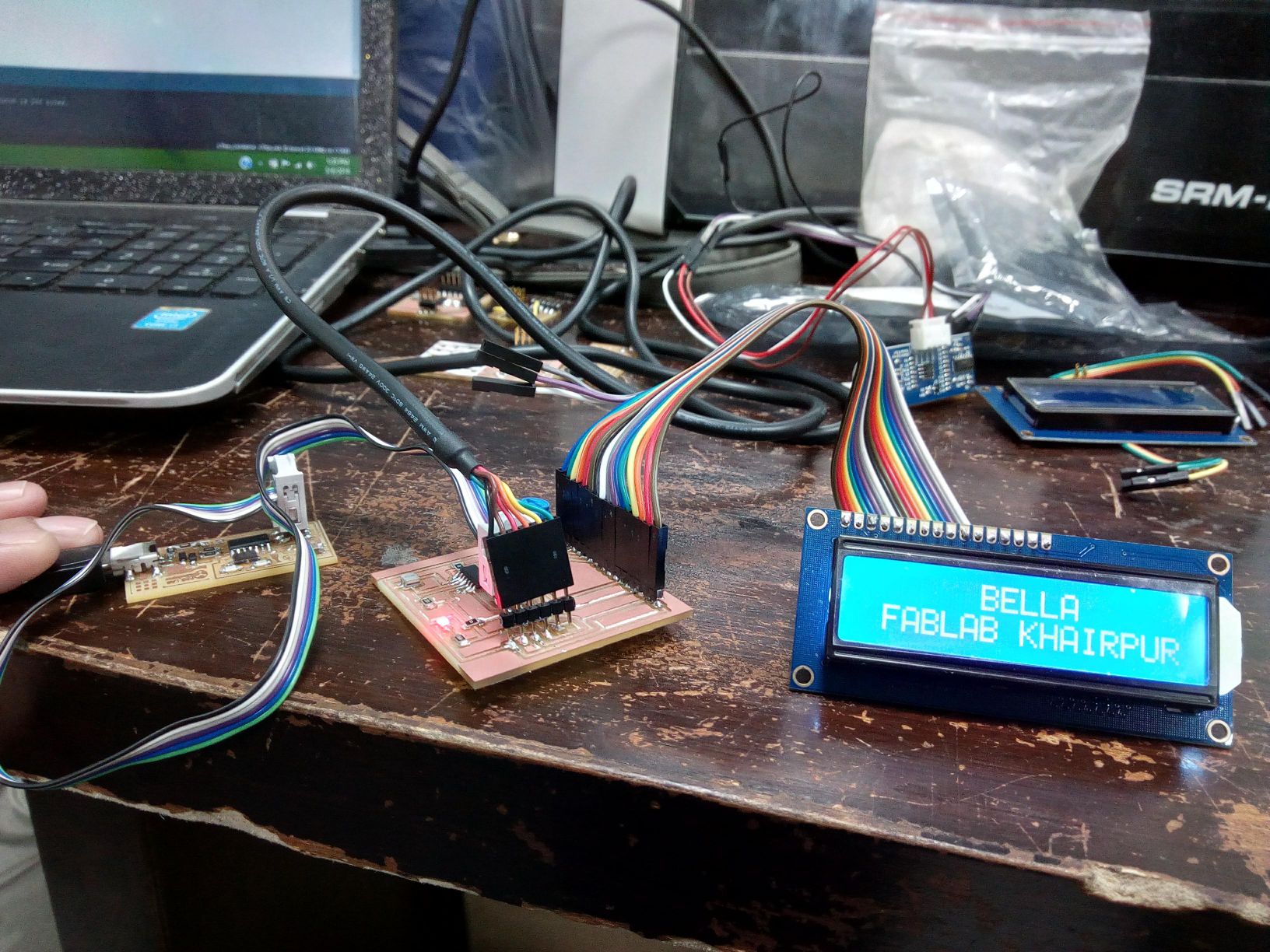
The final step was to upload the code for displaying on lcd. The code and output are shown below:
Group Assignment
In this week group assignment we have to measure power consumptions of an output device.
Measuring Power Consumption of RGB LEDs
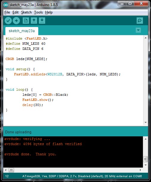
As one of our project is on RGB LEDs so we decide to find the power consumption of RGBs on different color pattern We write some codes which blink 1 RGB with specific color and measure current on that project
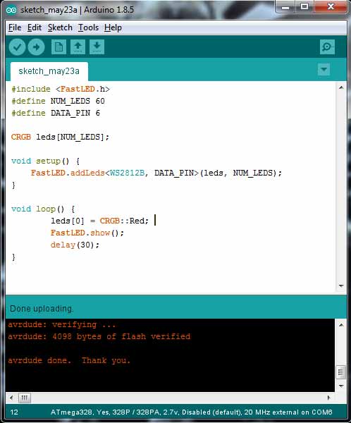
The current is measured 47mA which is multiplied with 5 Volts is equal to 235mW

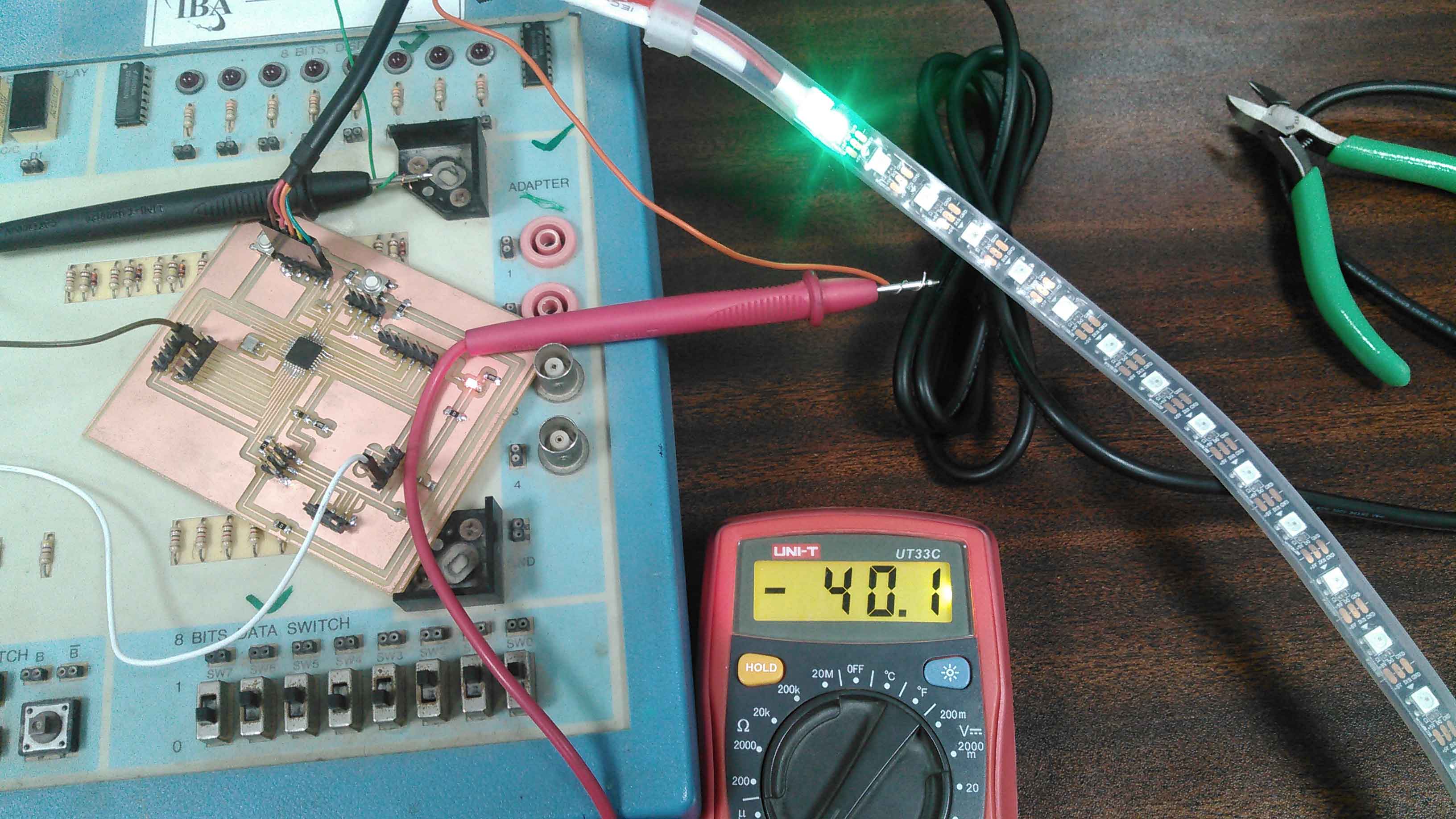
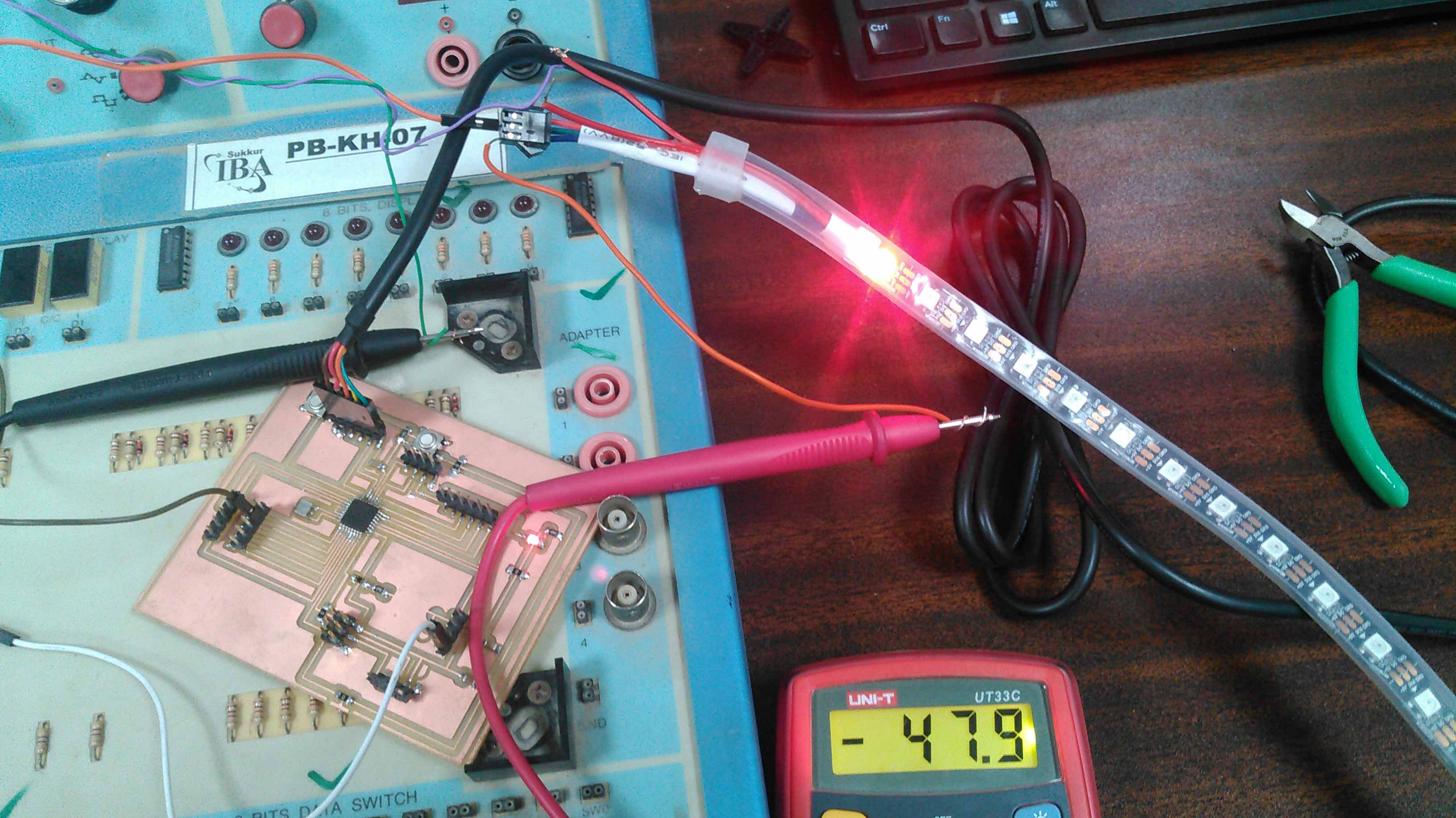
Checking current of RGB when 1 Green is on The current is measured 40mA which is multiplied with 5 Volts is equal to 200mW
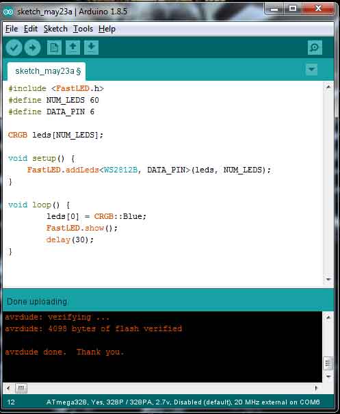
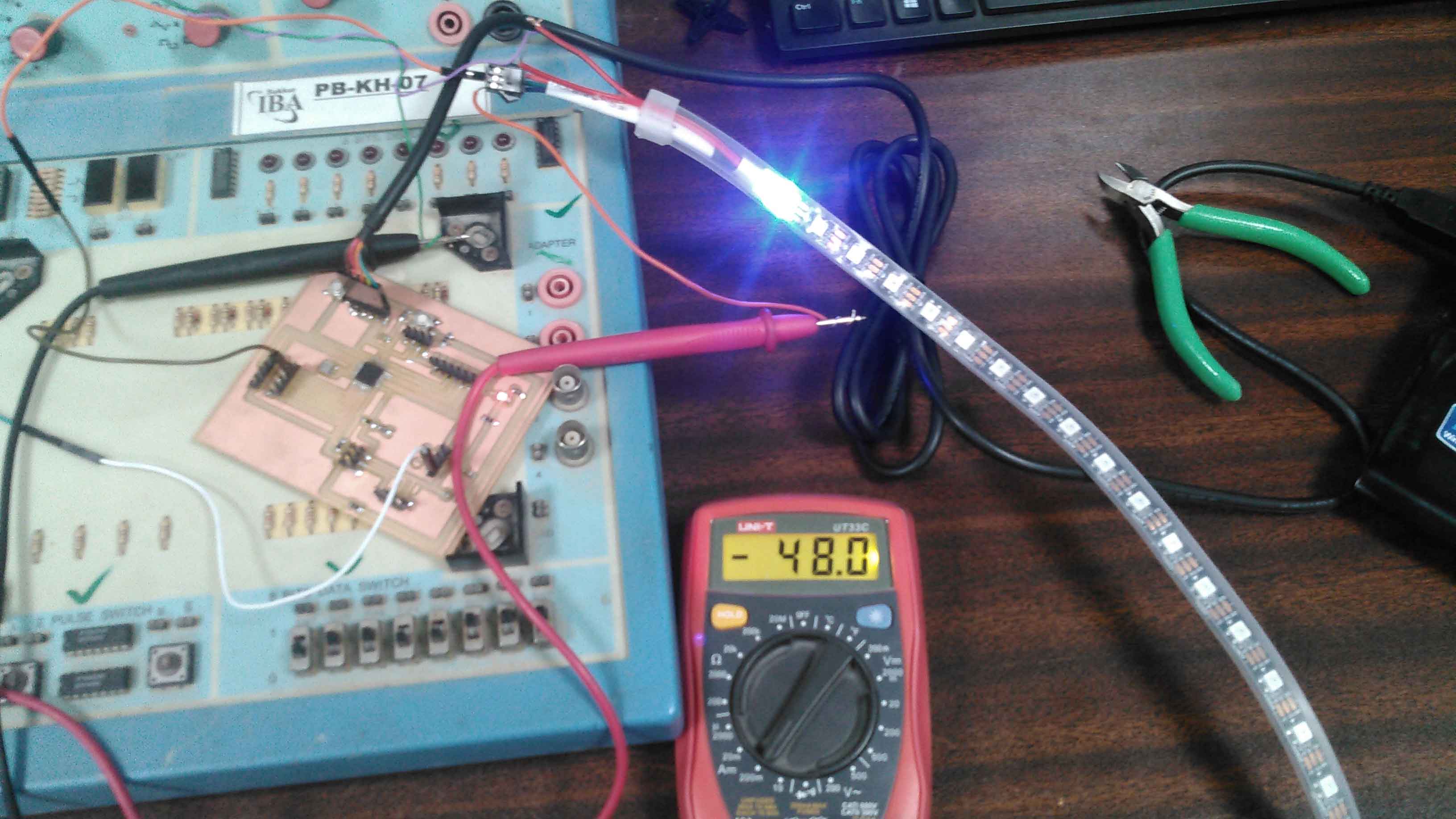
The current is measured 48mA which is multiplied with 5 Volts is equal to 240mW

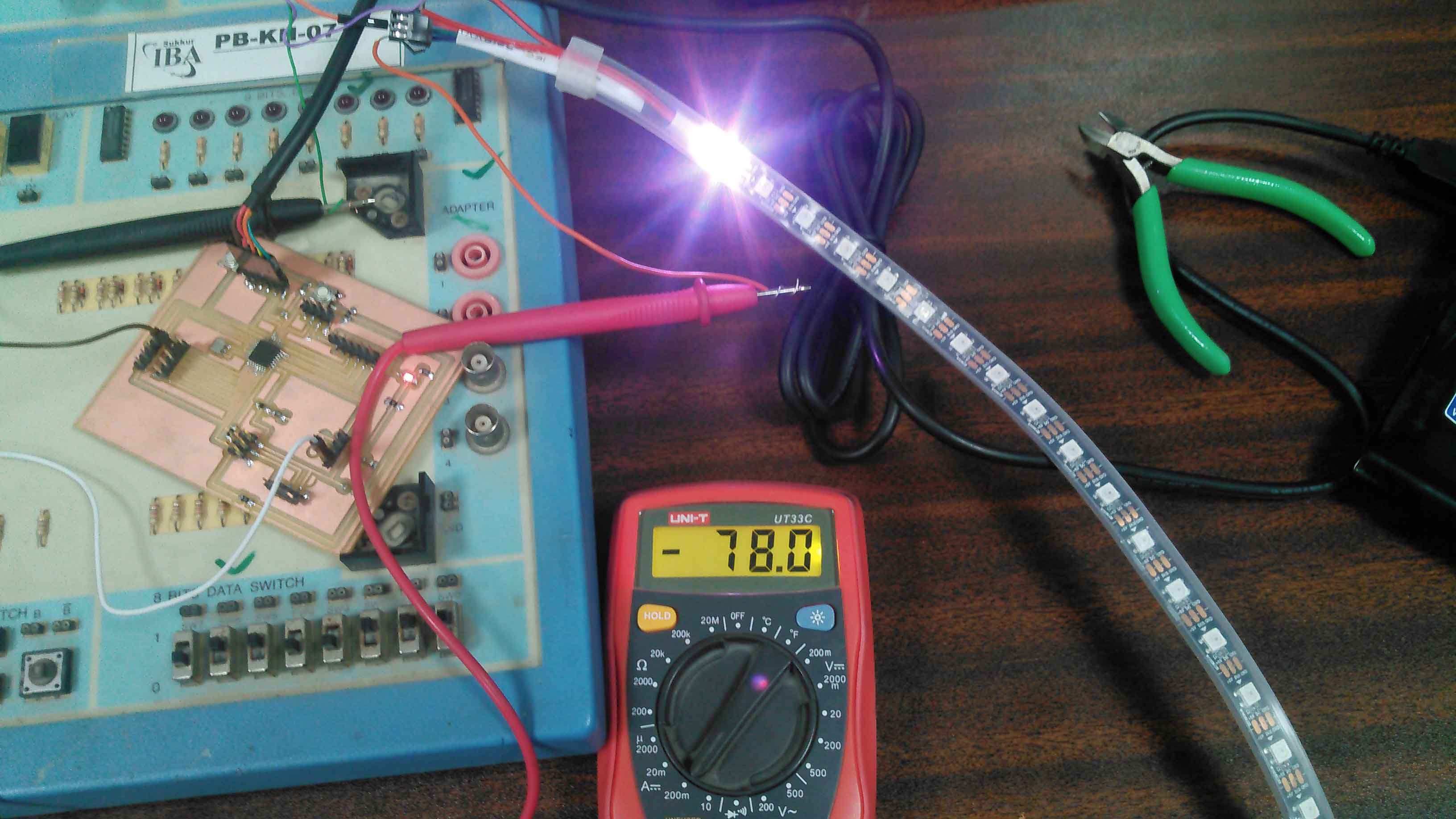
The current is measured 78mA which is multiplied with 5 Volts is equal to 390mW
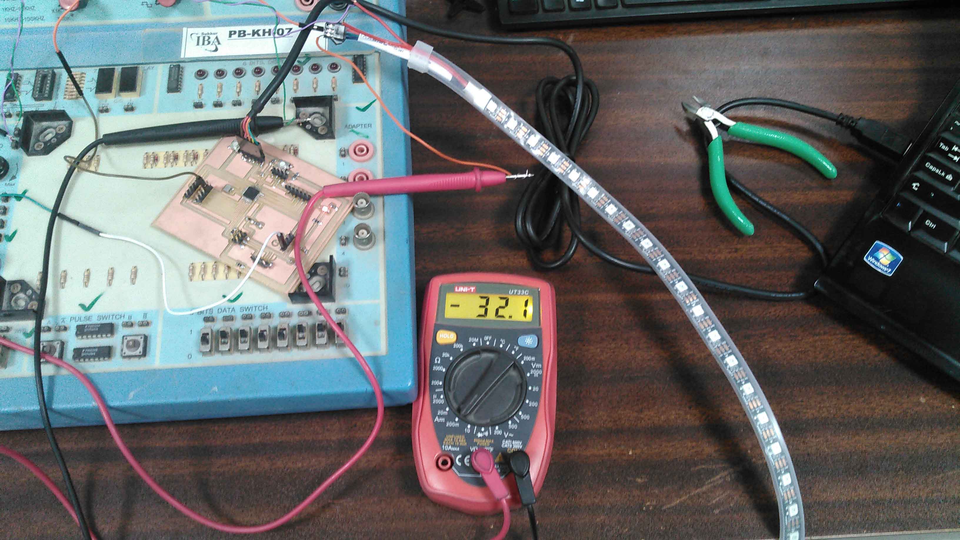
The current is measured 32.1mA which is multiplied with 5 Volts is equal to 160.5mW Different colors have different current consumptions. As per results we found that green color have low power consumption and white has maximum power consumption.
The files for this week are attached HERE

This work is licensed under a Creative Commons Attribution-NonCommercial 4.0 International License.