

Success is a journey, not a destination
Individual Assignment:
- measure something: add a sensor to a microcontroller board that you have designed and read it
Group Assignment:
- measure the analog levels and digital signals in an input device
Individual Task:
As part of this week's assignment, I need to interface any sensor with the board and using the sensor as an input device, I need to show the results.I have used almost all of these sensors durng my degree courses, I chose Ultrasonic sensor (HC-SR04) as my input device to measure the ditance.The basic concepts and working principle of the ultrasonic sensor are discussed below:
Ultrasonic Sensor:
Ultrasonic sensors emit an ultrasound at 40 KHz which travels through the air and if there is an object or obstacle on its path It will bounce back to the module. The distance is calculated by measuring the travel time and the speed of the sound.The HC-SR04 Ultrasonic Module has 4 pins, Ground, VCC, Trig and Echo. The Ground and the VCC pins of the module needs to be connected to the Ground and the 5 volts pins on the Arduino Board respectively and the trig and echo pins to any Digital I/O pin on the Arduino Board.
In order to generate the ultrasound you need to set the Trig on a High State for 10 µs. That will send out an 8 cycle sonic burst which will travel at the speed sound and it will be received in the Echo pin. The Echo pin will output the time in microseconds the sound wave traveled.To know more about the working of sensor click HERE

Milling the Board
The boards were provided in the class schedule, so I used the same board but with slight changes in it. I used EAGLE for this purpose.

In the next step, I checked for errors using ERC comand and cleared the warnings, as shown below:

The board was created and routing was performed, this is how the board finally looked like:
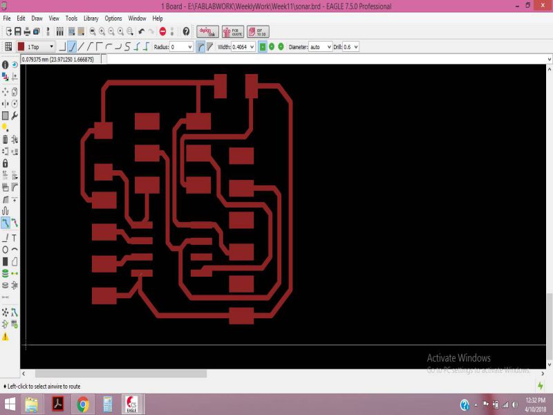
I had done routing several times, and I needed to adjust the trace width so that the paths do not merge while generating the rml files.

I exported the board and edited in paint, to create the traces and outline of the board.
I used fabmodules to generate the RML files,by following the same procedures as in the previous weeks.The Paths are given below, and the RML files at the end of the page.


It's now very easy to use Rolland SRM-20, It took me no time to mill the board, the following images show the PCB after being milled.

Soldering the components
Soldering the components has become the favorite part of assignment, because I can do soldering easily then I did earlier. the list of components is given below:
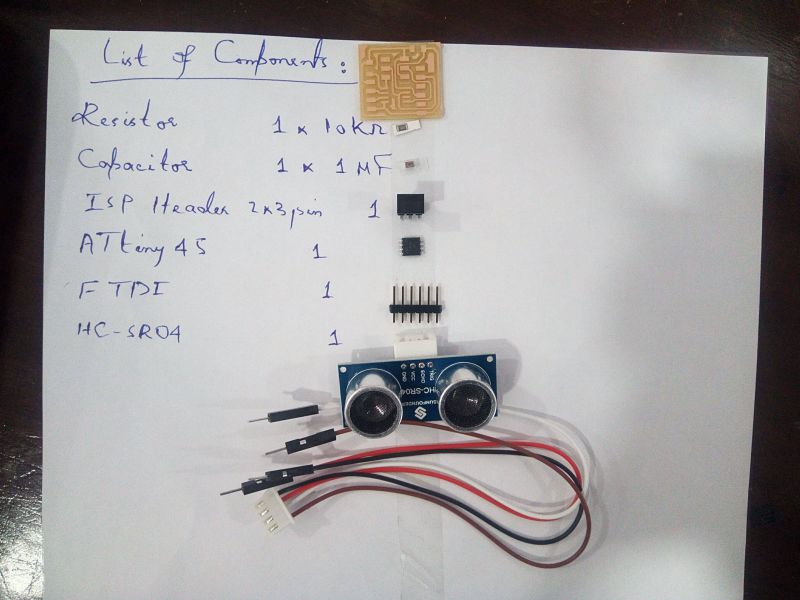
Within 15 minutes, I was able to solder the components, the board after soldering is given below:

Programming the Board
I have used Arduino IDE for programming, becuase I find it very easy to use and it makes the tsaks easier. Following are the steps needed for programming the Input device.
-
Select The Board From the Tools
.jpg)
- Select the Attiny45 Processor , and 1MHz internal Oscillato.
-
Select the programmer, USBTinyISP and Burn the bootloader in the microcontoller.
.jpg)
In the next step, I uploaded the code provided by Niel in the class schedule. Initially I could not get the proper result, because I was not using the Software Serial Library properly. After reading about the functionality of Software Serial library, I tried again. This time I got some results , but not accurate.
After Burning the bootloader, I opened the serial monitor to get the result of distance in cm, as I move any object away from the sensor
.jpg)
I had written in my name in ()"Serial.println") of the arduino code. I got this unusual result, as I would move the object far away I was getting less letters of my name on screen.
.jpg)
After making the connection again, I finally got the result of Distance in com, as shown in the Serial monitor below:
.jpg)
I will be using the Input Device in my upcoming Assignments too, So I am planning to make the same ciruit on Attiny44 too , so that I can have more I/O pins.
Conclusion:
Input Devices is really an important week from the perspective of electronics work, I intend to use the Input and Output weeks to cover some part of my final Project. Working with Atiny44 sometimes troubles because it has less pins and memory, but it was based on learning.
Group Task:
In this week group assignment we have to measure analog levels and digital signals in an input devices.
Measuring Analog Levels of Phototransistor
SFH 320 Silicon NPN Phototransistor is used by one of our group member in individual task in which the circuit is detecting light and displays result of light intensity on bar using python. So as the group assignment we measured the resistance of this component which is changed when we increase or decrease the intensity of lights on it. The resistance is measured by Digital Multimeter. We observe that at one instance when we increase the intensity of light resistance decreases and when we decrease intensity of light resistance increases.


Detecting Digital Signals in UltraSonic Sensor
HC SR-04 Ultrasonic sensor is used by one of our group member in his individual task of this week. We detect the change in digital signal in Oscilloscope using arduino UNO. A sensor is connected with arduino and the pin of Echo is connected with Oscilloscope. Arduino is program to detect obstacle in front of Ultrasonic sensor (a code is attached with files), when an obstacle is present in front of Ultrasonic sensor we found change in wave in oscilloscope


The Files of this week are attached below:
Week11 Files!

This work is licensed under a Creative Commons Attribution-NonCommercial 4.0 International License.