Week 11
Input Devices
Group assignment
Individual assignment
Learning outcomes:
- Demonstrate workflows used in circuit board design and fabrication.
- Implement and interpret programming protocols.
Have you:
- Described your design and fabrication process using words/images/screenshots.
- Explained the programming process/es you used and how the microcontroller datasheet helped you.
- Explained problems and how you fixed them.
- Included original design files and code.
Individual assignment:
A. Introduction to the inputs that I will use:
For my final project, the posture corrector, I would like to measure how the body changes when you are in a correct position vs when you are not. For doing so I am going to try four types of inputs:
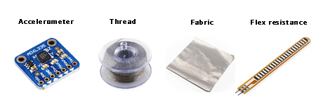
- Accelerometer: to measure the inclination of the body.
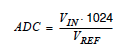
- Conductive thread, which has 28 Ohms/30cm.
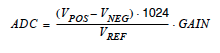
- Conductive fabric
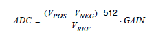
- Flexible resistance
How to read the input signals
For this week's assignment I needed to know how to read the Analog signals from my sensors. I went to the Analog to Digital converter section of AtTiny's 44 datahseet.
After the conversion is complete (ADIF is high), the conversion result can be found in the ADC Data Registers (ADCL, ADCH). The form of the conversion result depends on the type of conversion that you perform. We can distinguish three types of conversion:
- Single ended conversion: This is the one that I will use with the accelerometer and with the flex sensor.
- Unipolar differential conversion: The voltage of the positive pin must always be larger than the voltage of the negative pin or otherwise the voltage difference is saturated to zero.
- Bipolar differential conversion: this one I will use it with the conductive thread. If I was certain that my value is going to be always greater or smaller than the reference resistance I could use unipolar and like that I wouldn't loose a bit, but as this can vary, I will use this bipolar mode.
1. Accelerometer:
An accelerometer is an electromechanical device that measures acceleration forces. When measuring these forces we can have two forces: The static ones, like the constant force of gravity, or the dynamic ones that are caused by moving or vibrating the accelerometer. So, an accelerometer can be used to measure the static angle of tilt or inclination of a person.
Output: voltage proportional to the acceleration.
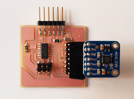
I will use an ADXL335 accelerometer, in particular the Adafruit one. Characteristics of the Adafruit accelerometer:
- Triple-axis accelerometer.
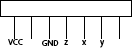
- In total it has 8 pins:
- VCC
- VCC at 3.3v directly.
- Ground
- Three analog pins.
- Test pin.
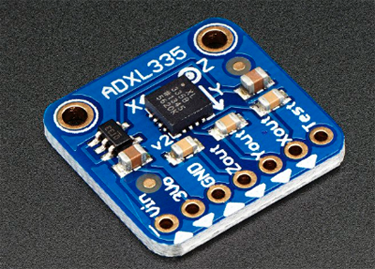
- The 3.3V regulator is integrated and it will it will save me from adding the regulator in the board.
- 3 analog outputs for X, Y and Z axis measurements.
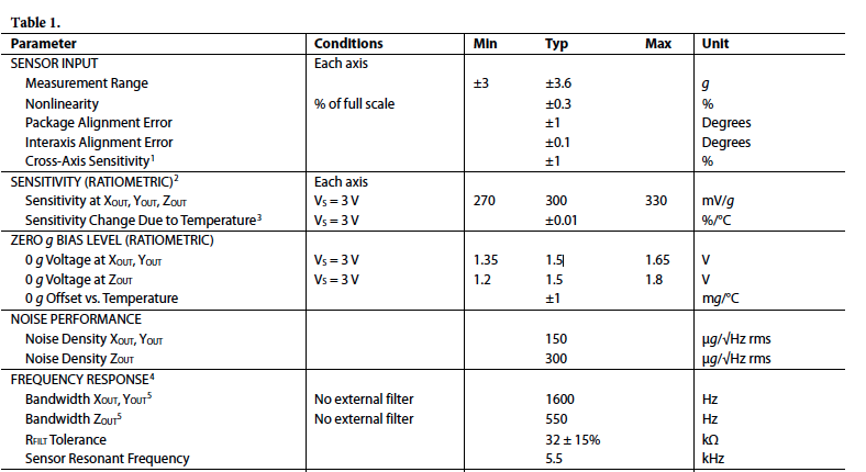
- Those three outputs are radiometric which means that:
- 0g measurement output is always at half of the 3.3V output (1.65V).
- -3g is at 0v
- 3g is at 3.3V with full scaling in between.
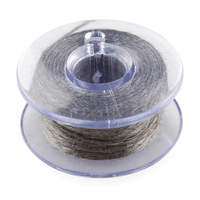
A. Designing the board for the accelerometer
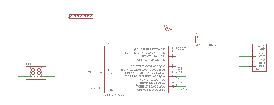
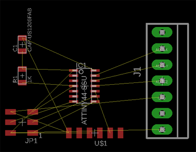
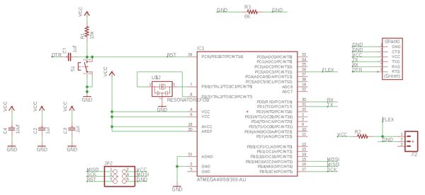
Schematic:
For this accelerometer I will design a board that will be then communicating with a main board that will receive and process the information. In this board I need:
- A 7 pin connector that will make the connection with the Adafruit. I've chosen the MTA07-156 from Eagle.
- ATTiny44
- 3x2 Header
- 1K Resistance for the reset pin
- 1uF capacitor for the VCC
- FTDI
- VCC and GND
For adding this components in Eagle I made use of the information gathered in Week 07. When designing the schematic I did a table where I have the names that I have to look for in the program to be able to add them.
 I add the components and I started to create the nets to join the different pins.
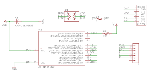
The final result of the schematic was this one:
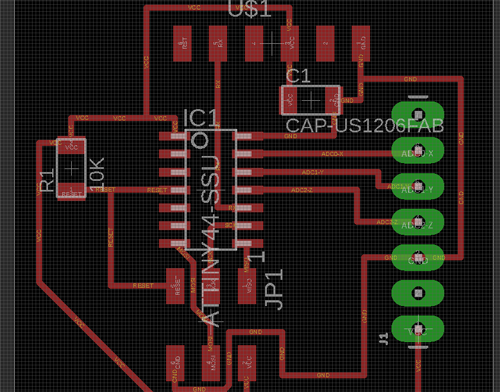
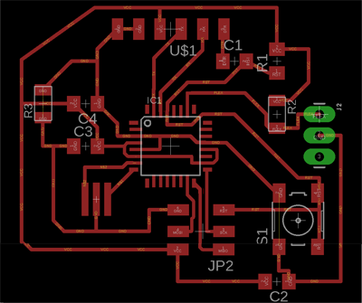
Board:
Once I had all the components in my schematic I switched to the board window and I started to display the components.
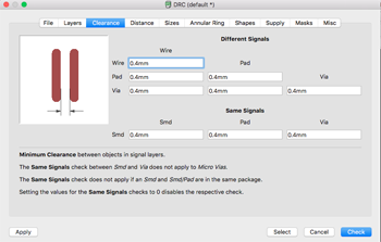
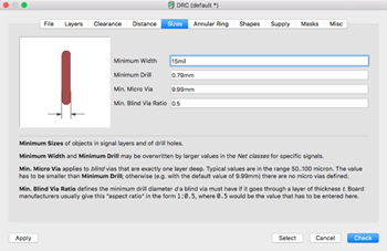
 In the same way I did on Week 07, I set the DRC to the constrains that I need when designing the board.
Then I organized the different components in the board.
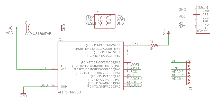
PROBLEM:
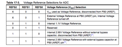
I thought it was ok like that but I didn't realize that as the accelerometer will work with voltage = 3.3v, I need to think about what voltage I will use as a reference. I can't use the 5V one, and the ATTiny 44 only has an internal one of 1.1V that won't be enough, so I needed to add a pin to the microcontroller that will communicate with the 3.3V pin of the accelerometer.
This voltage external reference , AREF, needs to go in pin PA0, so I had to modify the original schematic. I also changed the 7 pin connector for the Sparkfun one: CONN_07.
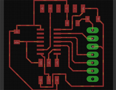
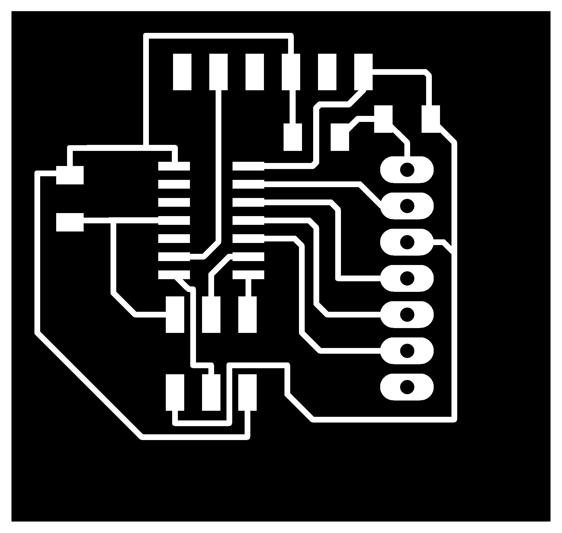
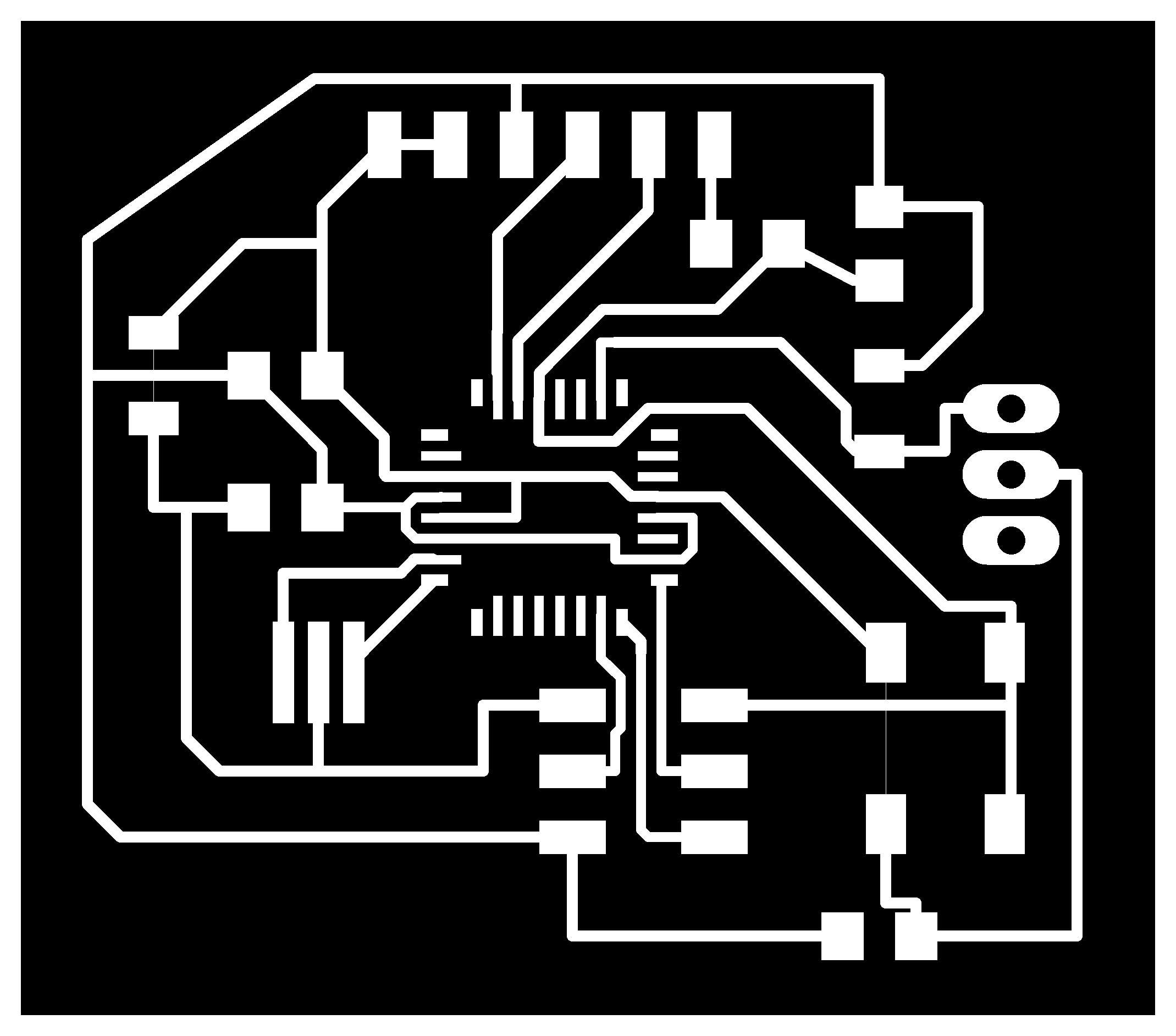
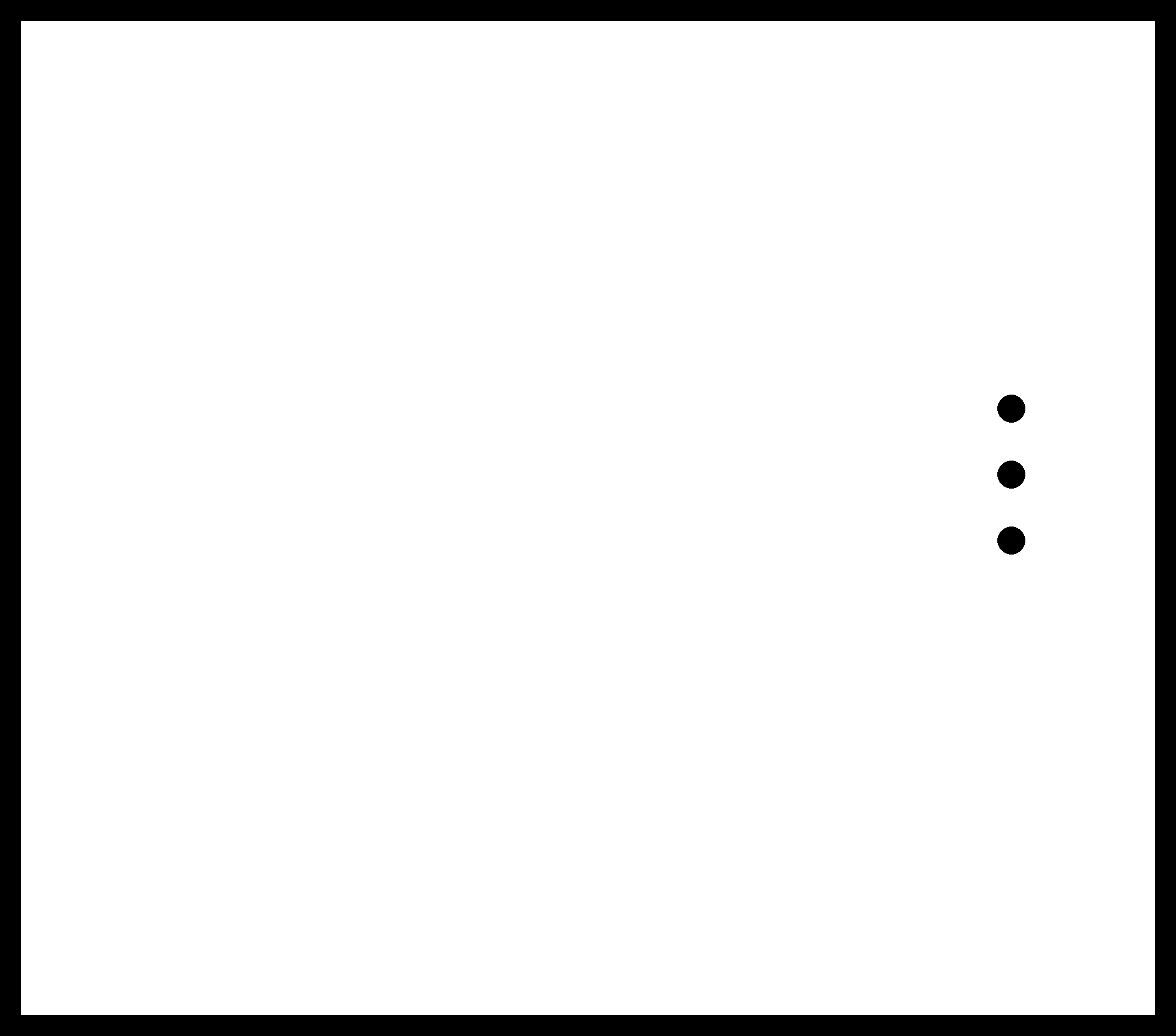
Once I changed that my board was ready to be exported as an image. In this case, as the connector had holes I had to choose not only the top layer but also the pads one.
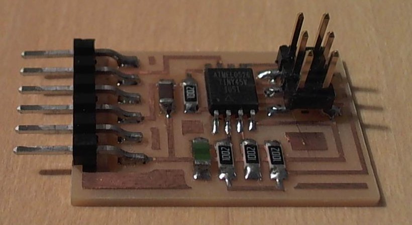
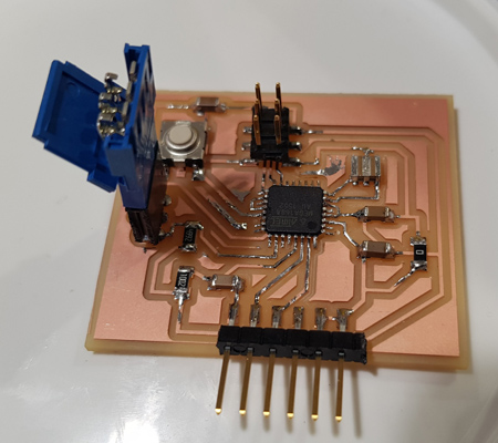
B. Milling and soldering:
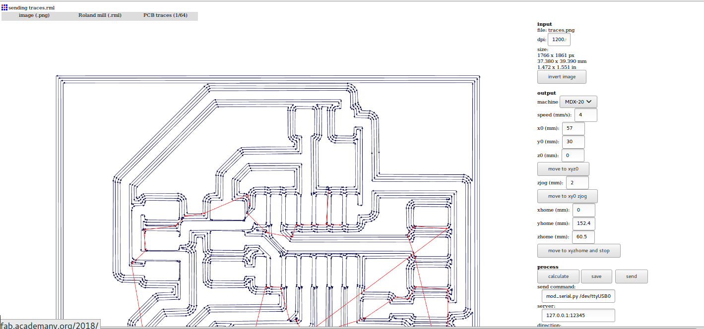
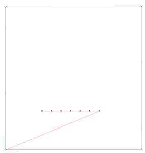
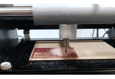
I milled the boards using Fabmodules, again, I followed the same process of the Week 07. I checked that all the traces were going to be milled properly and I send it to the Modela.
The components that I had to solder to the accelerometer board were:
- Attiny 44
- FTDI
- 1x7 connectors, both male and female
- 1uf capacitor
- 10K resistor
- SPI 3x2 header.
C. Programming the Accelerometer:
Structure of the accel.c program:
- Include the libraries and define the variables tat will be used. As I will reuse a program from Neil I will include the #define output, #define set....
- Look in the board design what port and pin are being used for the serial communication, and change the corresponding lines:#define serial_port PORTA
#define serial_direction DDRA
#define serial_pin_out (1 << PA7) - Include the put_char function to be able to send the data.
- As the accelerometer has three ADC ports I created a function called uint16_t readadc(uint8_t ch) where I will enable the corresponding ADC pin, depending on the axis, and I will start the conversion.
- Main function :
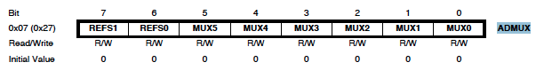
- Set the clock divider to 1, to know what registers and what values to give them, check the datasheet:
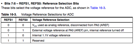
- Initialize the output pins and select the voltage reference value. I am using an External Voltage Reference, so I need to set FEFS0 to 1 and REFS1 to 0.
- Enable de ADC and set the prescaler to 128.
- And then in the while loop I will call the function to read the three values for x, y and z and I will send them in blocks of 8 bits.
PROBLEMS:
At first the accel.c file was not sending the data properly and after searching in the code what was the problem I found out several problems:
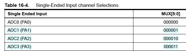
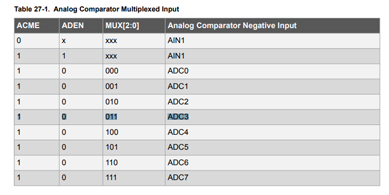
- First, instead of setting the registers for the ADC pins in ADMUX, I had left it like the template: ADCSRA. This means that I was not changing the register values that I wanted, so I changed for this:
ADMUX = (0 << MUX3)|(0 << MUX2)|(1 << MUX1)|(1 << MUX0); // ADC3 - x (011) - I changed this and the values were being sent but I was not getting what I was expecting. I was missing an | to clear the previous register configuration. So now it will look something like:
ADMUX = (0 << MUX3)|(0 << MUX2)|(1 << MUX1)|(1 << MUX0); // ADC3 - x (011) - But, by doing so I was clearing all the values of that register when setting it to read x,y and z, including in those values the voltage reference ones
- So in the end I decided to set the value that I wanted to read each of the ADC registers directly in binary.
accel.c (first correct version):
//
// hello.mag.45.c -- accel.c
//
// Hall effect magnetic sensing hello-world
// 9600 baud FTDI interface
//
// Neil Gershenfeld 11/3/13
// (c) Massachusetts Institute of Technology 2013
//
// This work may be reproduced, modified, distributed,
// performed, and displayed for any purpose. Copyright is
// retained and must be preserved. The work is provided
// as is; no warranty is provided, and users accept all
// liability.
//
//Modified by Victoria Peredo
//FabLab Madrid CEU
#include <avr/io.h>
#include <util/delay.h>
#define output(directions,pin) (directions |= pin) // set port direction for output
#define set(port,pin) (port |= pin) // set port pin
#define clear(port,pin) (port &= (~pin)) // clear port pin
#define pin_test(pins,pin) (pins & pin) // test for port pin
#define bit_test(byte,bit) (byte & (1 << bit)) // test for bit set
#define bit_delay_time 102 // bit delay for 9600 with overhead
#define bit_delay() _delay_us(bit_delay_time) // RS232 bit delay
#define half_bit_delay() _delay_us(bit_delay_time/2) // RS232 half bit delay
#define char_delay() _delay_ms(10) // char delay
//I changed the port to the one that I am using for RX: PORTA, pin PA7
#define serial_port PORTA

#define serial_direction DDRA

#define serial_pin_out (1 << PA7)
void put_char(volatile unsigned char *port, unsigned char pin, char txchar) {
//
// send character in txchar on port pin
// assumes line driver (inverts bits)
//
// start bit
//
clear(*port,pin);
bit_delay();
//
// unrolled loop to write data bits
//
if bit_test(txchar,0)
set(*port,pin);
else
clear(*port,pin);
bit_delay();
if bit_test(txchar,1)
set(*port,pin);
else
clear(*port,pin);
bit_delay();
if bit_test(txchar,2)
set(*port,pin);
else
clear(*port,pin);
bit_delay();
if bit_test(txchar,3)
set(*port,pin);
else
clear(*port,pin);
bit_delay();
if bit_test(txchar,4)
set(*port,pin);
else
clear(*port,pin);
bit_delay();
if bit_test(txchar,5)
set(*port,pin);
else
clear(*port,pin);
bit_delay();
if bit_test(txchar,6)
set(*port,pin);
else
clear(*port,pin);
bit_delay();
if bit_test(txchar,7)
set(*port,pin);
else
clear(*port,pin);
bit_delay();
//
// stop bit
//
set(*port,pin);
bit_delay();
//
// char delay
//
bit_delay();
}
//Function to read the ADC signal, depending on the channel that is selected we read ADC3, 3 or 1
uint16_t readadc(uint8_t ch)
{
if(ch == 3){
ADMUX = 0b01000011; // I wrote the registers value directly
//ADMUX |= (0 << MUX3) | (0 << MUX2) | (1 << MUX1) | (1 << MUX0); // ADC3 - x (011)
}
else if(ch == 2){
ADMUX = 0b01000010;
//ADMUX |= (0 << MUX3) | (0 << MUX2) | (1 << MUX1) | (0 << MUX0); // ADC2 - y (010)
}
else{
ADMUX = 0b01000001;
//ADMUX |= (0 << MUX3) | (0 << MUX2) | (0 << MUX1) | (1 << MUX0); // ADC1 - z (001)
}
ADCSRA|=(1<<ADSC); //START CONVERSION
while((ADCSRA)&(1<<ADSC))
;
//WAIT UNTIL CONVERSION IS COMPLETE
_delay_ms(1);
return(ADC); //Return the whole ADC value (16 bits)
}
int main(void) {
//Defining the variables where I will store the ADC signal
uint16_t x,y,z;
//
// main
//
//
// set clock divider to /1
//
CLKPR = (1 << CLKPCE);
CLKPR = (0 << CLKPS3) | (0 << CLKPS2) | (0 << CLKPS1) | (0 << CLKPS0);
//
// initialize output pins, calling the previously defined functions with the serial output (porta, pa7)
//
set(serial_port, serial_pin_out);
output(serial_direction, serial_pin_out);
//
// We initialize the ADC, we just do this the first time
//
ADMUX = (0 << REFS1) | (1 << REFS0); // I am using an external reference por the voltage in the PA0
ADCSRB = (0 << ADLAR) ;// right adjust
ADCSRA = (1 << ADEN) // enable ADC
| (1 << ADPS2) | (1 << ADPS1) | (1 << ADPS0); // prescaler /128
//
// main loop
//
while (1) {
//for 100 hilo = 32 bits
x=readadc(3); //when we send a 3 to the function, the ADC3 that is connected to the x signal will be read
y=readadc(2); //with a 2 the ADC2, the y signal
z=readadc(1); //and with a 1 the ADC1, the 1 signal
//
// send framing
//
put_char(&serial_port, serial_pin_out, 1);
char_delay();
put_char(&serial_port, serial_pin_out, 2);
char_delay();
put_char(&serial_port, serial_pin_out, 3);
char_delay();
put_char(&serial_port, serial_pin_out, 4);
char_delay();
//
// send result, as we are sending the 16 bits for each of the signals (x,y,z) we need to divide them in blocks of
// two to be able to send them
put_char(&serial_port, serial_pin_out, (x & 255));
char_delay();
put_char(&serial_port, serial_pin_out, ((x >> 8) & 255));
char_delay();
put_char(&serial_port, serial_pin_out, (y & 255));
char_delay();
put_char(&serial_port, serial_pin_out, ((y >> 8) & 255));
char_delay();
put_char(&serial_port, serial_pin_out, (z & 255));
char_delay();
put_char(&serial_port, serial_pin_out, ((z >> 8) & 255));
char_delay();
}
}
When this version was sending correctly the adc values I decided to crete a loop to send, instead of value by value, adding 100 samples to be able to average them and be more precise. For doing so I had to increment the size of the variable that is going to store my three signals, and send them in blocks of three instead of two.
accel.c with loop:
//
// hello.mag.45.c   -- accel.c
//
// Hall effect magnetic sensing hello-world
//    9600 baud FTDI interface
//
// Neil Gershenfeld 11/3/13
// (c) Massachusetts Institute of Technology 2013
//
// This work may be reproduced, modified, distributed,
// performed, and displayed for any purpose. Copyright is
// retained and must be preserved. The work is provided
// as is; no warranty is provided, and users accept all
// liability.
//
//Modified by Victoria Peredo
//FabLab Madrid CEU

#include <avr/io.h>
#include <util/delay.h>

#define output(directions,pin) (directions |= pin) // set port direction for output
#define set(port,pin) (port |= pin) // set port pin
#define clear(port,pin) (port &= (~pin)) // clear port pin
#define pin_test(pins,pin) (pins & pin) // test for port pin
#define bit_test(byte,bit) (byte & (1 << bit)) // test for bit set
#define bit_delay_time 102 // bit delay for 9600 with overhead
#define bit_delay() _delay_us(bit_delay_time) // RS232 bit delay
#define half_bit_delay() _delay_us(bit_delay_time/2) // RS232 half bit delay
#define char_delay() _delay_ms(10) // char delay

//I changed the port to the one that I am using for RX: PORTA, pin PA7

#define serial_port PORTA
#define serial_direction DDRA
#define serial_pin_out (1 << PA7)

#define nsamples 100 // number of samples to accumulate

void put_char(volatile unsigned char *port, unsigned char pin, char txchar) {
   //
   // send character in txchar on port pin
   //    assumes line driver (inverts bits)
   //
   // start bit
   //
   clear(*port,pin);
   bit_delay();
   //
   // unrolled loop to write data bits
   //
   if bit_test(txchar,0)
      set(*port,pin);
   else
      clear(*port,pin);
   bit_delay();
   if bit_test(txchar,1)
      set(*port,pin);
   else
      clear(*port,pin);
   bit_delay();
   if bit_test(txchar,2)
      set(*port,pin);
   else
      clear(*port,pin);
   bit_delay();
   if bit_test(txchar,3)
      set(*port,pin);
   else
      clear(*port,pin);
   bit_delay();
   if bit_test(txchar,4)
      set(*port,pin);
   else
      clear(*port,pin);
   bit_delay();
   if bit_test(txchar,5)
      set(*port,pin);
   else
      clear(*port,pin);
   bit_delay();
   if bit_test(txchar,6)
      set(*port,pin);
   else
      clear(*port,pin);
   bit_delay();
   if bit_test(txchar,7)
      set(*port,pin);
   else
      clear(*port,pin);
   bit_delay();
   //
   // stop bit
   //
   set(*port,pin);
   bit_delay();
   //
   // char delay
   //
   bit_delay();
   }

   //Function to read the ADC signal, depending on the channel that is selected we read ADC3, 3 or 1

   uint16_t readadc(uint8_t ch)
   {
      if(ch == 3){
        ADMUX = 0b01000011; // I wrote the registers value directly
         //ADMUX |= (0 << MUX3) | (0 << MUX2) | (1 << MUX1) | (1 << MUX0); // ADC3 - x (011)
      }
      else if(ch == 2){
        ADMUX = 0b01000010;
         //ADMUX |= (0 << MUX3) | (0 << MUX2) | (1 << MUX1) | (0 << MUX0); // ADC2 - y (010)
      }
      else{
        ADMUX = 0b01000001;
        //ADMUX |= (0 << MUX3) | (0 << MUX2) | (0 << MUX1) | (1 << MUX0); // ADC1 - z (001)
      }

      ADCSRA|=(1<<ADSC);            //START CONVERSION
      while((ADCSRA)&(1<<ADSC))
         ;

         //WAIT UNTIL CONVERSION IS COMPLETE
      _delay_ms(1);
      return(ADC);                  //Return the whole ADC value (16 bits)
   }

int main(void) {

   //Defining the variables where I will store the ADC signal
   uint16_t x,y,z;

   //I will use a loop for a bit more of accurate
   static uint16_t count;
   static uint32_t accum_x;
   static uint32_t accum_y;
   static uint32_t accum_z;
   //
   // main
   //
   //
   // set clock divider to /1
   //
   CLKPR = (1 << CLKPCE);
   CLKPR = (0 << CLKPS3) | (0 << CLKPS2) | (0 << CLKPS1) | (0 << CLKPS0);
   //
   // initialize output pins, calling the previously defined functions with the serial output (porta, pa7)
   //
   set(serial_port, serial_pin_out);
   output(serial_direction, serial_pin_out);
   //
   // We initialize the ADC, we just do this the first time
   //
   ADMUX = (0 << REFS1) | (1 << REFS0); // I am using an external reference por the voltage in the PA0
   ADCSRB =  (0 << ADLAR) ;// right adjust
   ADCSRA = (1 << ADEN) // enable ADC
      | (1 << ADPS2) | (1 << ADPS1) | (1 << ADPS0); // prescaler /128
   //
   // main loop
   //
   while (1) {

      accum_x = 0;
      accum_y = 0;
      accum_z = 0;

      for (count = 0; count < nsamples; ++count) {
         //
         // Call the function that sets the reading ADC (x,y or z)
         //
         x=readadc(3);      //when we send a 3 to the function, the ADC3 that is connected to the x signal will be read
         accum_x += x;

         y=readadc(2);      //with a 2 the ADC2, the y signal
         accum_y += y;

         z=readadc(1);      //and with a 1 the ADC1, the 1 signal
         accum_z += z;
         }
      //
      // send framing
      //
      put_char(&serial_port, serial_pin_out, 1);
      char_delay();
      put_char(&serial_port, serial_pin_out, 2);
      char_delay();
      put_char(&serial_port, serial_pin_out, 3);
      char_delay();
      put_char(&serial_port, serial_pin_out, 4);
      char_delay();

      //
      // send result, as we are sending the 16 bits for each of the signals (x,y,z) we need to divide them in blocks of
      // two to be able to send them


      put_char(&serial_port, serial_pin_out, (accum_x & 255));
      char_delay();
      put_char(&serial_port, serial_pin_out, ((accum_x >> 8) & 255));
      char_delay();
      put_char(&serial_port, serial_pin_out, ((accum_x >> 16) & 255));
      char_delay();
      put_char(&serial_port, serial_pin_out, (accum_y & 255));
      char_delay();
      put_char(&serial_port, serial_pin_out, ((accum_y >> 8) & 255));
      char_delay();
      put_char(&serial_port, serial_pin_out, ((accum_y >> 16) & 255));
      char_delay();
      put_char(&serial_port, serial_pin_out, (accum_z & 255));
      char_delay();
      put_char(&serial_port, serial_pin_out, ((accum_z >> 8) & 255));
      char_delay();
      put_char(&serial_port, serial_pin_out, ((accum_z >> 16) & 255));
      char_delay();

   }
}
Reading and displaying the data:
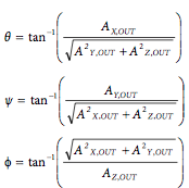
In order to know how to meassure the inclination by using the accelerometer I read this application Note that helps you to calculate the ideal inclination angle. I used a .py model from Neil to read the values that the board is sending through the .c progrma. In this python file what I am doing is first to read the signal, in the first version of .c in two blocks and in the second one in three, and put them together in a variable. Then I had to convert that input value to a voltage (at first I was not doing this conversion so my values had no sense). This can be done my using this formula:

 And then, with that voltage value the angle can be calculated:
Python version for the first version, without loop:
#
# hello.mag.45.py
#
# receive and display magnetic field
#    hello.mag.45.py serial_port
#
# Neil Gershenfeld 11/3/13
# (c) Massachusetts Institute of Technology 2013
#
# This work may be reproduced, modified, distributed,
# performed, and displayed for any purpose. Copyright is
# retained and must be preserved. The work is provided
# as is; no warranty is provided, and users accept all
# liability.

# accelerometer.py
# Modified by Victoria Peredo
#

from Tkinter import *
import serial
import numpy
import math

WINDOW = 800 # window size
nsamples = 100.0 # number of samples accumulated
vref = 3.3
sensi = 0.3
offset_xy = 512  #Value that the signals had when being laying flat
offset_z = 629


def idle(parent,canvas):
  global filter, eps
  #
  # idle routine
  #
  byte2 = 0
  byte3 = 0
  byte4 = 0
  ser.flush()
  while 1:
    #
    # find framing
    #
    byte1 = byte2
    byte2 = byte3
    byte3 = byte4
    byte4 = ord(ser.read())
    if ((byte1 == 1) & (byte2 == 2) & (byte3 == 3) & (byte4 == 4)):
       break

  #Theoretical vlevel = 1.5
  v_level_xy = (offset_xy*vref)/1024;
  v_level_z = (offset_z*vref)/1024;


  x1 = ord(ser.read())   #we read the first 8 bits
  x2 = ord(ser.read())   #we read the second 8 bits
  x_adc = (256*x2 + x1)   #we put them together in the same variable
  x_value = (((x_adc*vref)/1024)-v_level_xy)/sensi;      #Conversion to a voltage level


  #READING THE ACCELERATION OF Y

  y1 = ord(ser.read())
  y2 = ord(ser.read())
  y_adc = (256*y2 + y1)

  y_value = (((y_adc*vref)/1024)- v_level_xy)/sensi;

  #For reading the values that are being send from the ACDC we need re-build the two blocks

  #READING THE ACCELERATION OF Z

  z1 = ord(ser.read())
  z2 = ord(ser.read())
  z_adc = (256*z2 + z1)
  z_value = (((z_adc*vref)/1024)- v_level_z)/sensi;


  #Displaying the voltage value

  canvas.itemconfigure("accel_z",text="Voltage z %.1f"%z_value)
  canvas.itemconfigure("accel_x",text="Voltage x %.1f"%x_value)
  canvas.itemconfigure("accel_y",text="Voltage y %.1f"%y_value)


  #Calculating the angle in every axis with the voltage value: extracted from the datasheet

  if x_value==0:
    x_value = 0.001
  if y_value==0:
    y_value = 0.001
  if z_value==0:
    z_value = 0.001

  x_angle = math.atan(x_value / (math.sqrt((y_value**2) + (z_value**2)))) * (180/math.pi);

  y_angle = math.atan(y_value / (math.sqrt((x_value**2) + (z_value**2)))) * (180/math.pi);

  z_angle = math.atan((math.sqrt((x_value**2) + (y_value**2)))/z_value) * (180/math.pi);

  canvas.itemconfigure("angle_x",text="Angle x %.1f"%x_angle)
  canvas.itemconfigure("angle_y",text="Angle y %.1f"%y_angle)
  canvas.itemconfigure("angle_z",text="Angle z %.1f"%z_angle)

  #Calculating the total angle

  total_angle = math.acos(z_value / (math.sqrt((x_value**2) + (y_value**2) + (z_value**2)))) * (180/math.pi);

  canvas.itemconfigure("angle_total",text="Total angle:  %.1f"%total_angle)

  canvas.update()
  parent.after_idle(idle,parent,canvas)

#
#  check command line arguments
#
if (len(sys.argv) != 2):
   print "command line: accel.py serial_port"
   sys.exit()
port = sys.argv[1]
#
# open serial port
#
ser = serial.Serial(port,9600)
ser.setDTR()
#
# set up GUI
#
root = Tk()
root.title('Accelerometer (q to exit)')
root.bind('q','exit')
canvas = Canvas(root, width=WINDOW, height=.7*WINDOW, background='white')

canvas.create_text(.2*WINDOW,.2*WINDOW,text=".33",font=("Helvetica", 24),tags="accel_x",fill="#0000b0") # x acceleration value
canvas.create_text(.2*WINDOW,.4*WINDOW,text=".33",font=("Helvetica", 24),tags="angle_x",fill="#0000b0") # x angle

canvas.create_text(.5*WINDOW,.2*WINDOW,text=".33",font=("Helvetica", 24),tags="accel_y",fill="#0000b0") # y ADC value
canvas.create_text(.5*WINDOW,.4*WINDOW,text=".33",font=("Helvetica", 24),tags="angle_y",fill="#0000b0") # x angle

canvas.create_text(.8*WINDOW,.2*WINDOW,text=".33",font=("Helvetica", 24),tags="accel_z",fill="#0000b0") # z ADC value
canvas.create_text(.8*WINDOW,.4*WINDOW,text=".33",font=("Helvetica", 24),tags="angle_z",fill="#0000b0") # x angle

canvas.create_text(.5*WINDOW,.6*WINDOW,text=".33",font=("Helvetica", 24),tags="angle_total",fill="#0000b0") # total angle
canvas.pack()
#
# start idle loop
#
root.after(100,idle,root,canvas)
root.mainloop()
Python version for the first version, without loop:
#
# hello.mag.45.py
#
# receive and display magnetic field
#    hello.mag.45.py serial_port
#
# Neil Gershenfeld 11/3/13
# (c) Massachusetts Institute of Technology 2013
#
# This work may be reproduced, modified, distributed,
# performed, and displayed for any purpose. Copyright is
# retained and must be preserved. The work is provided
# as is; no warranty is provided, and users accept all
# liability.

# accelerometer.py
# Modified by Victoria Peredo
#

from Tkinter import *
import serial
import numpy
import math

WINDOW = 800 # window size
nsamples = 100.0 # number of samples accumulated
vref = 3.3
sensi = 0.3
offset_xy = 512
offset_z = 629
nsamples = 100.0 # number of samples accumulated


def idle(parent,canvas):
  global filter, eps
  #
  # idle routine
  #
  byte2 = 0
  byte3 = 0
  byte4 = 0
  ser.flush()
  while 1:
    #
    # find framing
    #
    byte1 = byte2
    byte2 = byte3
    byte3 = byte4
    byte4 = ord(ser.read())
    if ((byte1 == 1) & (byte2 == 2) & (byte3 == 3) & (byte4 == 4)):
       break

  #Theoretical vlevel = 1.5
  v_level_xy = (offset_xy*vref)/1024;
  v_level_z = (offset_z*vref)/1024;

  #leer 3 trozoz y dividir entre 100  -> mirar media y si no mediana

  x1 = ord(ser.read())   #we read the first 8 bits
  x2 = ord(ser.read())   #we read the second 8 bits
  x3 = ord(ser.read())   #we read the third 8 bits
  x_adc = (256*256*x3 + 256*x2 + x1)/nsamples   #we put them together in the same variable
  x_value = (((x_adc*vref)/1024)-v_level_xy)/sensi;      #Conversion to a voltage level


  #READING THE ACCELERATION OF Y

  y1 = ord(ser.read())
  y2 = ord(ser.read())
  y3 = ord(ser.read())
  y_adc = (256*256*y3 + 256*y2 + y1)/nsamples
  y_value = (((y_adc*vref)/1024)- v_level_xy)/sensi;

  #For reading the values that are being send from the ACDC we need re-build the two blocks

  #READING THE ACCELERATION OF Z

  z1 = ord(ser.read())
  z2 = ord(ser.read())
  z3 = ord(ser.read())
  z_adc = (256*256*z3 + 256*z2 + z1)/nsamples
  z_value = (((z_adc*vref)/1024)- v_level_z)/sensi;


  #Displaying the voltage value

  canvas.itemconfigure("accel_z",text="Voltage z %.1f"%z_value)
  canvas.itemconfigure("accel_x",text="Voltage x %.1f"%x_value)
  canvas.itemconfigure("accel_y",text="Voltage y %.1f"%y_value)


  #Calculating the angle in every axis with the voltage value: extracted from the datasheet

  if x_value==0:
    x_value = 0.001
  if y_value==0:
    y_value = 0.001
  if z_value==0:
    z_value = 0.001

  x_angle = math.atan(x_value / (math.sqrt((y_value**2) + (z_value**2)))) * (180/math.pi);

  y_angle = math.atan(y_value / (math.sqrt((x_value**2) + (z_value**2)))) * (180/math.pi);

  z_angle = math.atan((math.sqrt((x_value**2) + (y_value**2)))/z_value) * (180/math.pi);

  canvas.itemconfigure("angle_x",text="Angle x %.1f"%x_angle)
  canvas.itemconfigure("angle_y",text="Angle y %.1f"%y_angle)
  canvas.itemconfigure("angle_z",text="Angle z %.1f"%z_angle)

  #Calculating the total angle

  total_angle = math.acos(z_value / (math.sqrt((x_value**2) + (y_value**2) + (z_value**2)))) * (180/math.pi);

  canvas.itemconfigure("angle_total",text="Total angle:  %.1f"%total_angle)

  canvas.update()
  parent.after_idle(idle,parent,canvas)

#
#  check command line arguments
#
if (len(sys.argv) != 2):
   print "command line: accel.py serial_port"
   sys.exit()
port = sys.argv[1]
#
# open serial port
#
ser = serial.Serial(port,9600)
ser.setDTR()
#
# set up GUI
#
root = Tk()
root.title('Accelerometer (q to exit)')
root.bind('q','exit')
canvas = Canvas(root, width=WINDOW, height=.7*WINDOW, background='white')

canvas.create_text(.2*WINDOW,.2*WINDOW,text=".33",font=("Helvetica", 24),tags="accel_x",fill="#0000b0") # x acceleration value
canvas.create_text(.2*WINDOW,.4*WINDOW,text=".33",font=("Helvetica", 24),tags="angle_x",fill="#0000b0") # x angle

canvas.create_text(.5*WINDOW,.2*WINDOW,text=".33",font=("Helvetica", 24),tags="accel_y",fill="#0000b0") # y ADC value
canvas.create_text(.5*WINDOW,.4*WINDOW,text=".33",font=("Helvetica", 24),tags="angle_y",fill="#0000b0") # x angle

canvas.create_text(.8*WINDOW,.2*WINDOW,text=".33",font=("Helvetica", 24),tags="accel_z",fill="#0000b0") # z ADC value
canvas.create_text(.8*WINDOW,.4*WINDOW,text=".33",font=("Helvetica", 24),tags="angle_z",fill="#0000b0") # x angle

canvas.create_text(.5*WINDOW,.6*WINDOW,text=".33",font=("Helvetica", 24),tags="angle_total",fill="#0000b0") # total angle
canvas.pack()
#
# start idle loop
#
root.after(100,idle,root,canvas)
root.mainloop()
This python program was displaying the voltage values, the angle in each axis and the total angle in a canvas.
.zip with all the accelerometer files:
- Two versions of the .c program (one with loop and the other one without, accel.c and accel_loop.c)
- Make file to run the .c script
- Two versions of the .py programs, again, one with loop, accel_loop.py and another one without it, accel.py
- Eagle files, both schematic and board design
- Pictures of the board and the schematic
- Images of the traces and the outside+holes
2. Conductive thread:
The purpose of the this and the flexible resistance inputs are to measure the length variation of the muscles when the posture changes. What I did was:
- Measuring different back muscles in two different positions, straight and slumped, to see which ones change the most and what was that variation.
- Once I had that, I sew three pieces of thread with different stitches in a cotton t-shirt to study what the max resistence and min resistence of the thread is when stretching and in the resting state.
- Then I followed the same process for the conductive fabric. I measure what the resistance was when being in the resting state and when stretching it.
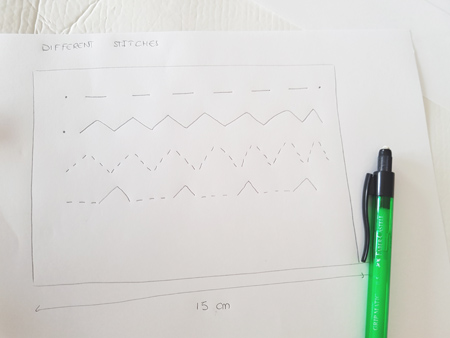 When measuring the thread that I had sew straight, few changes were observed as this material is non-elastic and it was not varying in size when stretching. At first I though that the third way will be the optimal but when I measure the resistance value, the one who had a bigger difference when stretching 2 cm was the second way. More info will be added in the project description.
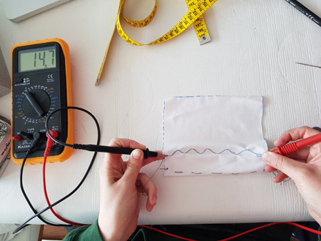
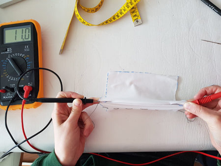
Length variance : 2cm:
· Stretching : Resistance = 11 ohms.
· Resting state: Resistance = 14.7 ohms.
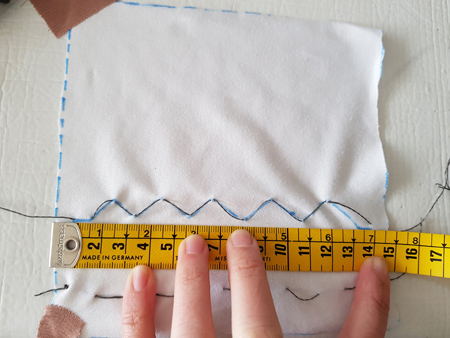
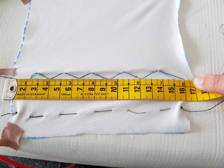
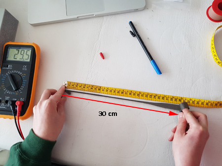
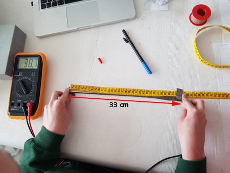
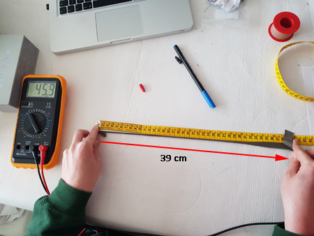
So for the conductive thread I measure those values: the maximum resistence, when the thread is stretched, and the minimum resistence, when I measure the thread without stretching.
A. Downloading the board files:
In order to do the first test with this material I will use the already designed temperature board as it has what I need, a Wheatstone Bridge.
I downloaded the corresponding files for the temperature sensor Click here to find the files where you can find the board design, the traces, the outside and the component image. And what I had to do was to calculate the values my resistances will have. This calculations are explained in the Milling and soldering part.

B. Milling and soldering:
The components that I needed to solder to the thread board:
- Microcontroller : ATTiny 45
- SPI connector, 3x2 header.
- 4 resistances: one the 10K resistance needed for the reset pin and the other three for the Wheatstone bridge that I needed for measure the resistance of my thread. As the values of this thread are very small I need to calculate the resistances needed for the Wheatstone bridge. We had resistances of 10ohms and 1/4 power in the Fablab so I checked if there will be ok.
Vout = 2.5V
Rmax thread = 14.7ohms
Rmin thread = 11 ohms
Intensity =2.5V 14'7+11= 0.09727 A
Power = V · I = 0'2432. So I can use those resistance.
Three 10omhs resistance and 10k one. - A 1uf capacitor
- FTDI connector.
C. Programming the conductive thread sensor:
For the conductive thread I was using the temperature board, so for programming I first downloaded Neil's .c code and I run it without making any changes, just changing the name, to check it.
I went to the file location in the console and I execute the make file to compile the .c code:
$sudo make -f thread.make program-usbtiny
For the python code I modified it as I didn't need the calculations that were done for the temperature. I only needed to:
- Read the low and high values.
- Multiply them by 256 to have the complete value (the value is sent to the computer in 2byte segments).
- I used the filter that Neil uses in the functions to have a more stable value.
- Checked the sign bit to know whether the value is positive or negative.
- Calculate the ADV result which as we are using Bipolar Differential conversion is given by this equation:
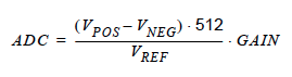
Here you have the python.py code that I used.
    # thread.py
    #
    # receive and display temperature
    # hello.temp.45.py serial_port
    #
    # Neil Gershenfeld
    # CBA MIT 3/27/12
    #
    # (c) Massachusetts Institute of Technology 2012
    # Permission granted for experimental and personal use;
    # license for commercial sale available from MIT
    #

    #Edited by Victoria Peredo
    #FabLab CEU

    from Tkinter import *
    from numpy import log
    import serial

    WINDOW = 600 # window size
    eps = 0.5 # filter time constant
    filter = 0.0 # filtered value

    def idle(parent,canvas):
       global filter, eps
       #
       # idle routine
       #
       byte2 = 0
       byte3 = 0
       byte4 = 0
       ser.flush()
       while 1:
          #
          # find framing
          #
          byte1 = byte2
          byte2 = byte3
          byte3 = byte4
          byte4 = ord(ser.read())
          if ((byte1 == 1) & (byte2 == 2) & (byte3 == 3) & (byte4 == 4)):
             break


       low = ord(ser.read())
       high = ord(ser.read())
       value = 256*high + low
       filter = (1-eps)*filter+eps*value
       if (value > 511):
           value -= 1024
       V = 2.5 - value*5.0/(20.0*512.0)

       filter = (1-eps)*filter + eps*V

       x = int(.2*WINDOW + (.9-.2)*WINDOW*filter/1024.0)
       canvas.itemconfigure("text",text="Value: %.1f"%filter)
       canvas.coords('rect1',.2*WINDOW,.05*WINDOW,x,.2*WINDOW)
       canvas.coords('rect2',x,.05*WINDOW,.9*WINDOW,.2*WINDOW)
       canvas.update()
       parent.after_idle(idle,parent,canvas)


    #
    #  check command line arguments
    #
    if (len(sys.argv) != 2):
       print "command line: hello.temp.45.py serial_port"
       sys.exit()
    port = sys.argv[1]
    #
    # open serial port
    #
    ser = serial.Serial(port,9600)
    ser.setDTR()
    #
    # start plotting
    #
    root = Tk()
    root.title('Thread resistance (q to exit)')
    root.bind('q','exit')
    canvas = Canvas(root, width=WINDOW, height=.25*WINDOW, background='#eeeded')
    canvas.create_text(.1*WINDOW,.125*WINDOW,text=".33",font=("Helvetica", 20),tags="text",fill="#000000")
    canvas.create_rectangle(.2*WINDOW,.05*WINDOW,.3*WINDOW,.2*WINDOW, tags='rect1', fill='#62d1ff')
    canvas.create_rectangle(.3*WINDOW,.05*WINDOW,.9*WINDOW,.2*WINDOW, tags='rect2', fill='#ffffff')
    canvas.pack()
    root.after(100,idle,root,canvas)
    root.mainloop()
PROBLEM:
I got some errors when executing the python script as I didn't have Numpy installed on my computer, so I went to this site and I downloaded the installation package for mac 'numpy-1.6.1-py2.7-python.org-macosx10.6.dmg'. Then I went to the console and I wrote pip install numpy.
Running the python script and displaying value:
Once I had done this I executed the python script: python thread.py /dev/cu.usbserial-FTFMJ6MW, specifying the serial port that I was using.
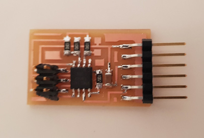
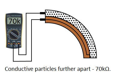
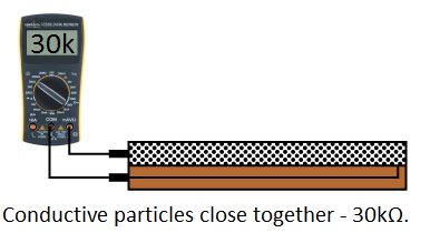
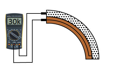
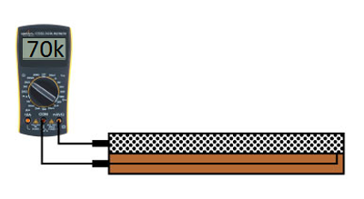
3. Flexible resistance: Redrawing FabKit
The flex sensor is printed with a polymer ink that has conductive particles embedded in it. When the sensor is laying flat these particles give the ink a resistor about 30Komhs, in my case around 25kohms. When I bend the sensor these particles move further apart increasing the resistance value, reaching around 50-70kohms when being at 90º.
A. Designing the board:
For using the flexible resistance I needed a voltage divider. In this case I will use the FabKit board adding some modifications on it. I downloaded the Fabkit file and I cloned it in order to change the components that I had in the schematic. I removed some of the connectors that I didn't need and I added a 3x1 connector that I will use for the flexible resistance.
Then I redraw the board display as I had removed and add new components. I added a 0k resistor in order to be able to communicate two pins. I had some trouble when joining the microcontroller's pins as they are quite small and the wire had clearance problems. I normally use 16mil width trace and in some parts I had to use 15mil one for it to fit.
B. Milling and soldering the components:
Components that need to be solder to the board:
- Attiny 168
- FTDI
- 3x2 SPI header
- One 1uf capacitor, one of 10uf and two 0.1uf capacitors
- One 10Kohms resistor, one 39.9Kohms resistor and 10ohms resistor
- SPI 3x2 header
- Button
- 8Mhz resonator
- 3x01 connector
Programming the flexible resistance:
For programming the flexible resistance board I was based on the light example. Here you have the .c code that I used.
// flex.c
//
// phototransistor hello-world
//   9600 baud FTDI interface
//
// Neil Gershenfeld
// 10/27/10
//
// (c) Massachusetts Institute of Technology 2010
// This work may be reproduced, modified, distributed,
// performed, and displayed for any purpose. Copyright is
// retained and must be preserved. The work is provided
// as is; no warranty is provided, and users accept all
// liability.
//
// Modified by Victoria Peredo
// FabLab Madrid CEU

#include <avr/io.h>
#include <util/delay.h>

#define output(directions,pin) (directions |= pin) // set port direction for output
#define set(port,pin) (port |= pin) // set port pin
#define clear(port,pin) (port &= (~pin)) // clear port pin
#define pin_test(pins,pin) (pins & pin) // test for port pin
#define bit_test(byte,bit) (byte & (1 << bit)) // test for bit set
#define bit_delay_time 102 // bit delay for 9600 with overhead
#define bit_delay() _delay_us(bit_delay_time) // RS232 bit delay
#define half_bit_delay() _delay_us(bit_delay_time/2) // RS232 half bit delay
#define char_delay() _delay_ms(10) // char delay


//OUTPUT ports, do not mix with inputs, here we need to know where is RX

#define serial_port PORTD
#define serial_direction DDRD
#define serial_pin_out (1 << PD0)

void put_char(volatile unsigned char *port, unsigned char pin, char txchar) {
   //
   // send character in txchar on port pin
   //    assumes line driver (inverts bits)
   //
   // start bit
   //
   clear(*port,pin);
   bit_delay();
   //
   // unrolled loop to write data bits
   //
   if bit_test(txchar,0)
      set(*port,pin);
   else
      clear(*port,pin);
   bit_delay();
   if bit_test(txchar,1)
      set(*port,pin);
   else
      clear(*port,pin);
   bit_delay();
   if bit_test(txchar,2)
      set(*port,pin);
   else
      clear(*port,pin);
   bit_delay();
   if bit_test(txchar,3)
      set(*port,pin);
   else
      clear(*port,pin);
   bit_delay();
   if bit_test(txchar,4)
      set(*port,pin);
   else
      clear(*port,pin);
   bit_delay();
   if bit_test(txchar,5)
      set(*port,pin);
   else
      clear(*port,pin);
   bit_delay();
   if bit_test(txchar,6)
      set(*port,pin);
   else
      clear(*port,pin);
   bit_delay();
   if bit_test(txchar,7)
      set(*port,pin);
   else
      clear(*port,pin);
   bit_delay();
   //
   // stop bit
   //
   set(*port,pin);
   bit_delay();
   //
   // char delay
   //
   bit_delay();
   }

int main(void) {
   //
   // main
   //
   static char chr;
   //
   // set clock divider to /1
   //
   //The CLKPCE must be written to logic one to enable change of the CLKPS bits.
   CLKPR = (1 << CLKPCE);
   //we set them all to 0 to set division factor to 1
   CLKPR = (0 << CLKPS3) | (0 << CLKPS2) | (0 << CLKPS1) | (0 << CLKPS0);
   //
   // initialize output pins
   //
   set(serial_port, serial_pin_out);
   output(serial_direction, serial_pin_out);
   //
   // init A/D
   //
   // Vcc ref;  (0,0,1 for external reference)
   ADMUX = (0 << REFS2) | (0 << REFS1) | (0 << REFS0)
      | (0 << ADLAR) // right adjust
      | (0 << MUX3) | (0 << MUX2) | (1 << MUX1) | (1 << MUX0);
   // ADC3   = my pin is PC3 = ADC3, which is (0,0,1,1)
   ADCSRA = (1 << ADEN) // enable ADC
      | (1 << ADPS2) | (1 << ADPS1) | (1 << ADPS0); // prescaler /128
   //
   // main loop
   //
   while (1) {
      //
      // send framing
      //
      put_char(&serial_port, serial_pin_out, 1);
      char_delay();
      put_char(&serial_port, serial_pin_out, 2);
      char_delay();
      put_char(&serial_port, serial_pin_out, 3);
      char_delay();
      put_char(&serial_port, serial_pin_out, 4);
      char_delay();
      //
      // initiate conversion
      //
      ADCSRA |= (1 << ADSC);
      //
      // wait for completion
      //
      while (ADCSRA & (1 << ADSC))
         ;
      //
      // send result
      //
      chr = ADCL;
      put_char(&serial_port, serial_pin_out, chr);
      char_delay();
      chr = ADCH;
      put_char(&serial_port, serial_pin_out, chr);
      char_delay();
      }
   }
In order to visualize the values that this program was sending I created a python file based on Neil's example also:
flex.py
#
# flex.py
#
# receive and display temperature
# hello.temp.45.py serial_port
#
# Neil Gershenfeld
# CBA MIT 3/27/12
#
# (c) Massachusetts Institute of Technology 2012
# Permission granted for experimental and personal use;
# license for commercial sale available from MIT
#
# Modified by Victoria Peredo
# FabLab Madrid CEU

from Tkinter import *
from numpy import log
import serial

WINDOW = 600 # window size
eps = 0.5 # filter time constant
filter = 0.0 # filtered value
vcc = 2.98
div_resis = 24600 #Measured resistance value of the voltage divider res

def idle(parent,canvas):
   global filter, eps
   #
   # idle routine
   #
   byte2 = 0
   byte3 = 0
   byte4 = 0
   ser.flush()
   while 1:
      #
      # find framing
      #
      byte1 = byte2
      byte2 = byte3
      byte3 = byte4
      byte4 = ord(ser.read())
      if ((byte1 == 1) & (byte2 == 2) & (byte3 == 3) & (byte4 == 4)):
         break
   low = ord(ser.read())
   high = ord(ser.read())
   adc = 256*high + low
   flexVolt = adc*vcc/1024
   #flexRes = div_resis*(vcc/flexVolt-1)
   flexRes = (((vcc*div_resis)/flexVolt)-div_resis)/1000

   #x = int(.2*WINDOW + (.9-.2)*WINDOW*flexRes)
   canvas.itemconfigure("adc",text="ADC: %.1f"%adc)
   canvas.itemconfigure("volt",text="Volt of res: %.1f"%flexVolt)
   canvas.itemconfigure("res",text="Res (Kohms): %.1f"%flexRes)
   #canvas.coords('rect1',.2*WINDOW,.05*WINDOW,x,.2*WINDOW)
   #canvas.coords('rect2',x,.05*WINDOW,.9*WINDOW,.2*WINDOW)
   canvas.update()
   parent.after_idle(idle,parent,canvas)


#
#  check command line arguments
#
if (len(sys.argv) != 2):
   print "command line: hello.temp.45.py serial_port"
   sys.exit()
port = sys.argv[1]
#
# open serial port
#
ser = serial.Serial(port,9600)
ser.setDTR()
#
# start plotting
#
root = Tk()
root.title('Thread resistance (q to exit)')
root.bind('q','exit')
canvas = Canvas(root, width=WINDOW, height=WINDOW, background='#eeeded')
canvas.create_text(.5*WINDOW,.1*WINDOW,text=".33",font=("Helvetica", 40),tags="adc",fill="#000000")
canvas.create_text(.5*WINDOW,.4*WINDOW,text=".33",font=("Helvetica", 40),tags="volt",fill="#000000")
canvas.create_text(.5*WINDOW,.7*WINDOW,text=".33",font=("Helvetica", 40),tags="res",fill="#000000")
#canvas.create_rectangle(.2*WINDOW,.05*WINDOW,.3*WINDOW,.2*WINDOW, tags='rect1', fill='#62d1ff')
#canvas.create_rectangle(.3*WINDOW,.05*WINDOW,.9*WINDOW,.2*WINDOW, tags='rect2', fill='#ffffff')
canvas.pack()
root.after(100,idle,root,canvas)
root.mainloop()
I moved to the file where I had the different scripts and I executed make file: sudo make -f flex.make program-usbtiny. Then I executed the pyhton file python flex.py /dev/cu.usbserial-FTFMJ6MW
In the explanation that I did before I said that acording to the tutorials the value of the resistance when its extended was around 30kohms and bended close to 70kohms. In my case (as you can see in the video) I obtain the oposite values, higher when the resistance is not bended and lower when it is. This values were also obtained when measuring directly with the multimeter.
Group assignment:
Group assignment pageFor this week's assignment we had to measure the analog levels and digital signals in an input device. We started by measuring some circuits with the Saint Smart Osilloscope DSO NoteII.
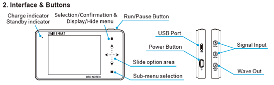
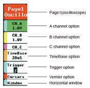
For using this oscilloscope we need to connect the probe to both ground and the part we aim to measure. Then we go to the menu and we enable the channels that we are going to read. In this case we were only measuring with the Channel A. you can also modify the voltage that will be represented, the timebase and how the signal will be displayed, if we are going to start reading when a trigger that we have set up occurs or if it is reading in an automatic way. In this assignment we read the signals from different circuits:
1. A circuit, connected to Arduino for the power supply, with a LDR.
2. Voltage variance when the we change the power of the potentiometer:
3. Moving the accelerometer to see changes of voltage in the Y axis:
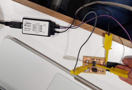
Using Saleae to measure input signals
We also used Saleae logic analyzer to measure and visualize the signals in our electrical circuits. We used the board of Week 07 running first a program that will light up the LED with different delay times.
#include <SoftwareSerial.h>

SoftwareSerial mySerial(0, 1); // RX, TX

const int id = '1';
const int ids = 1;
const int ledPin = PA3; //PA7
int ledState;


void setup() {
pinMode(ledPin, OUTPUT);
mySerial.begin(9600);
}

void loop() {
  if (mySerial.available()>0){
    ledState = mySerial.read();
    if (ledState == id){
      digitalWrite(ledPin,HIGH);
      delay(500);
      digitalWrite(ledPin,LOW);
      delay(500);
      digitalWrite(ledPin,HIGH);
      delay(500);
      digitalWrite(ledPin,LOW);
      delay(500);
      mySerial.println(ids);
  }
  else{
      digitalWrite(ledPin,HIGH);
      delay(500);
      digitalWrite(ledPin,LOW);
  }

  }
  delay(10);

}
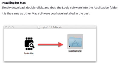
Downloading the required software:
We downloaded the software from the webpage.
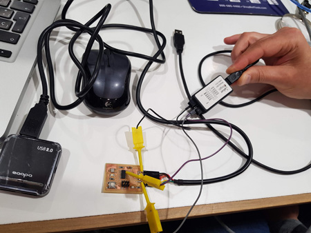
Connecting the wires to the board
To measure analyze our signals we need to plug the pins of the Salea analyzer to the pins that we are working with. In this case the two connected to the LED and to ground.
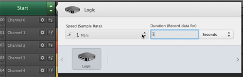
Working with logic.app
In this case we just need to know to what channels we have pluged our pins, conect it to the usb port and stablish how many seconds do we want to record on the start button.
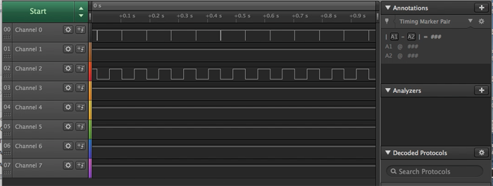
Here we can see how the voltage is changing when the LEDs being on and off. In this case one was connected to channel 0 and the other one to channel 2.
Analysing serial signals
We also analyze the signals when using the serial port. For doing so we uploaded Neil's hello.ftdi code. Then we changed the connectors to the pins that we had defined as RX and TX.
This time we had to create the signal Analyzers for both RX and TX channels. The way of doing this is by clicking on the + symbol on the right of Analyzers->Async serial.
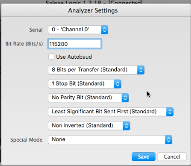
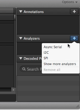 And then choosing the channels that we are using and modyfying the baud speed according to the one we have in our board.
 When this is ready we can open a serial monitor to send the letters to the microcontroller and like that we can see how the communication is done with the analyzer. You can also modify the way the information is being displayed (binary, dec, ASCII...) This is shown in the next video:
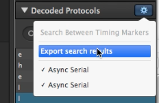
Data can be saved in the computer.
Downloads:
- Accelerometer board: Click here to download the zip file
- Thread board (designs of the temperature board): Click here to download the zip file
- Flexible resistance board (Fabkit): Click here to download the zip file