Week 15
Mechanical Design
Group assignment
Learning outcomes:
- Work and communicate effectively in a team and independently.
- Design, plan and build a system.
- Analyse and solve technical problems.
- Recognise opportunities for improvements in the design.
Have you:
- Shown how your team planned and executed the project.
- Described problems and how the team solved them.
- Listed future development opportunities for this project.
- Included your design files, 1 min video (1920x1080 HTML5 MP4) + slide (1920x1080 PNG).
Group assignment page
Inspiration
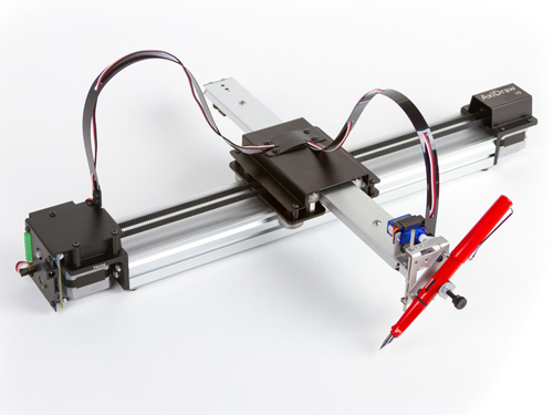
When developing the design of the machine we were inspired by the Axidraw Drawing Machine. This machine consist in two axis being the Y axis fixed to the X one. The aim was to design a 2-axis machine that could then hold a pen or knife to draw or cut vinyls.
Creating the stages in Rhino
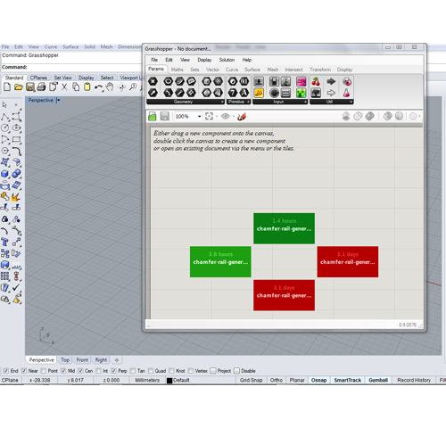
In order to design this machine we used Fellesverkstedet repository, downloading the chamferail grasshoper axis generator.
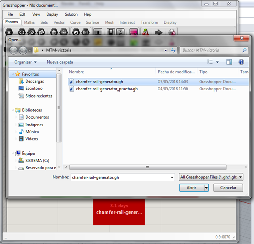
We opened the Grasshopper in Rhino by typing in the command. Then we went to File->OpenFile and a window opened to select the Grasshopper file.
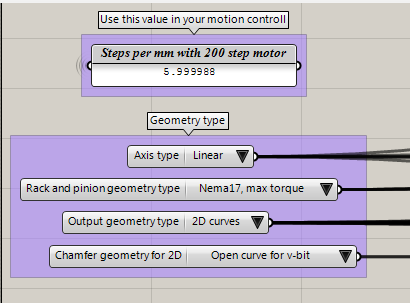
This tool allows you to costume the axis in order to fit our specifications. First thing we did was:
- Select the Axis type: linear
- Select the motor that we will be using: Nema 17
- Select v-bit tool to do the chamfer
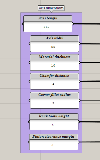
Then we need to specify the dimensios of the axis, in this case we were doing the Y axis. This size is related to the one given to the X axis which is 600mm. Here we also specify the thickness of the material that we are using:
| Length | 550mm |
|---|---|
| Axis width | 55mm |
| Material thickness: | 10mm |
| Chamfer distance | 4mm |
| Corner fillet radius | 5mm |
| Rack tooth radius | 4mm |
| Pinion clearance margin | 3mm |
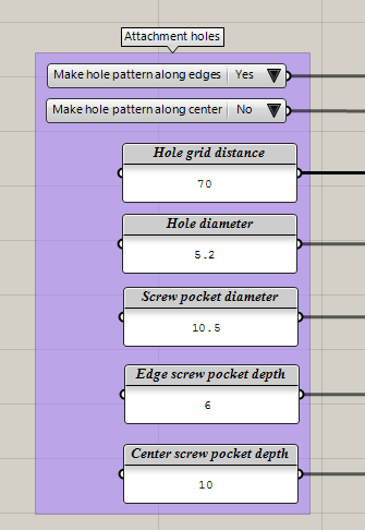
Attachment holes: when creating the stage with the grasshopper we draw this attachment holes but then most of them were removed from the design as we didn't really need them.
| Hole grid distance | 70mm |
|---|---|
| Diameter of the hole | 5.20mm |
| Screw pocket diameter | 10.5 mm |
| Edge screw pocket depth | 6mm |
| Center screw pocket depth | 10mm |
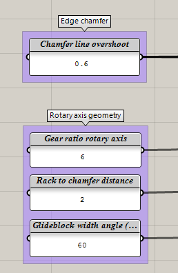
Edge chamfer: these values were left as default.
| Chamfer line overshoot | 0.6 mm |
|---|---|
| Gear ratio rotary axis | 6 mm |
| Rack to changer distance | 2 mm |
| Glideblock width angle | 60 mm |
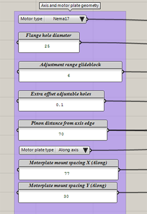
Axis and motor plate geometry: The motor support size was constraint by the size of the X axis. This support needed to fit on top of the X axis to be able to attach them.
| Flange hole diameter | 25 mm |
|---|---|
| Adjustment range glideblock | 6 mm |
| Extra offset adjustable holes | 0.1 mm |
| Pinion distance from axis edge | 70 mm |
| Motorplate mount spacing X (along) | 77 mm |
| Motorplate mount spacing Y (along) | 30 mm |
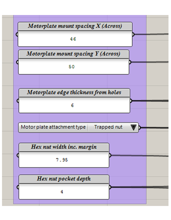
| Motorplate mount spacing X (Across) | 46 mm |
| Motorplate mount spacing Y (Across) | 50 mm |
| Motorplate edge thickness from holes | 6 mm |
| Hex nut with inc. margin | 7.95 mm |
| Hex nut pocket depth | 4 mm |
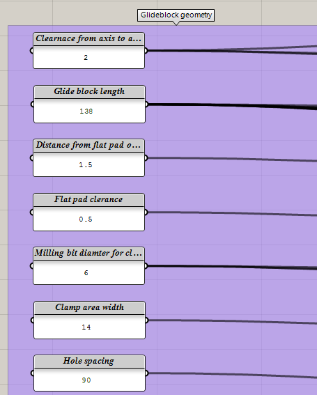
Then we changed the dimensions of the Glide Block as said before we want it to fit in the support of the X axis so we measured what was the length of that piece and changed the length of the Y axis.
| Clearnace from axis | 2 mm |
|---|---|
| Glide block length | 138 mm |
| Distance from flat pad | 1.5 mm |
| Flat pad clearance | 0.5 mm |
| Milling bit diameter for clearance | 6 mm |
| Clamp area width | 14 mm |
| Hole spacing | 90 mm |
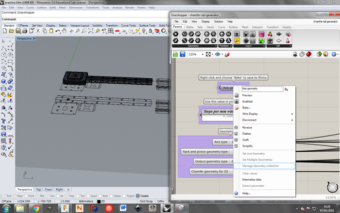
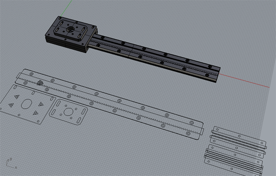
When we finished setting the parameters required for our machine we went back to the top part of the grasshopper file and we right-clicked on the Axis generator, and clicked on Bake.... For doing the 3D we just needed to change the Output geometry type and repeat the baking process.
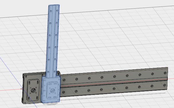
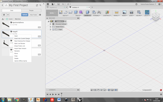
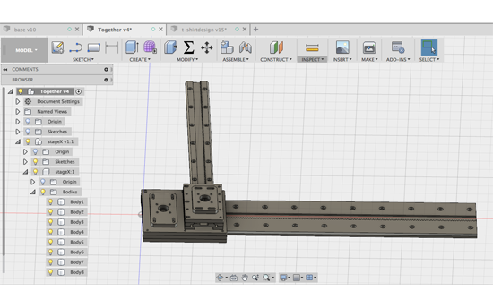
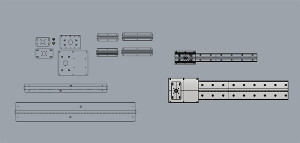
Working in Fusion
Once we had both designs, we put them together in Fusion 360 to check that the measurements were correct and both pieces fitted in the way we wanted to. We created a new design and we inserted both axis in the current design. Like this if the pieces are modified this design will also change.
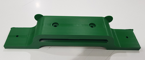
Designing the legs of the machine
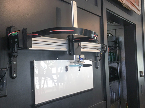
Then we designed the legs that will give support to the machine. The idea is that it can be either attached to a table or to a hung in a wall. For doing so we projected the side of the X stage and as this legs will be 3D printed we created an offset of 0.5mm for tolerance reasons.
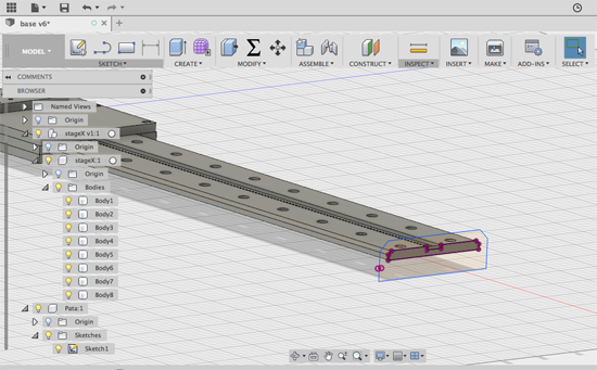
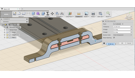
Then we gave the legs a length to be able to put a hole for attachment purposes and then drilled the holes that will allow the union between the axis and the leg. As it can be observed in the picture we removed part of the material from the bottom as we checked how long it will take to 3D print this piece and it was too long. By removing some of this material we lowered down this time.
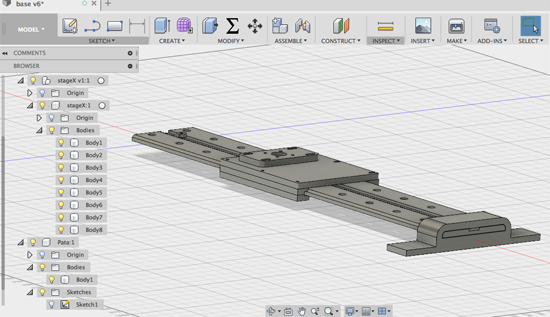
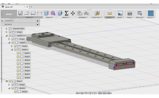
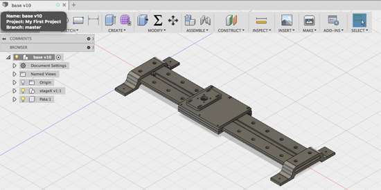
The final design of the X axis with both legs will look like this:
3D printing the legs
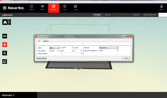
Once the design was done we exported the file as an .stl in Fusion and we opened in Mekerboot's software. To avoid the use of supports we flattened down the figure to one side. The first time we printed the legs we set these parameters:
- Quality: low
- Layer height: 0.34 mm
- Infill: 5%
- Temperature: 205º
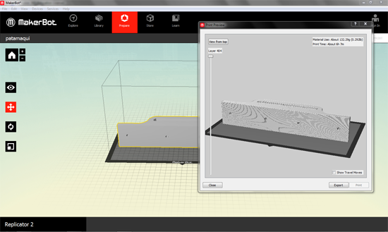
With this settings the estimation of printing time was 3 hours and 30 minutes.
Milling the parts of the machine
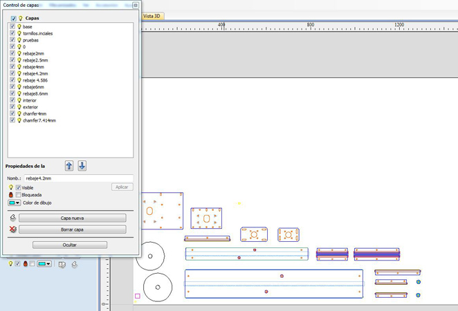
For milling the design we first had to export the .dxf files from Rhino, the 2D files that were generated with the Grasshopper. But before doing so, we needed to separate the pieces that will be milled with different tools (6mm, 3mm and 2mm) in different layers, as well as the different types of cuts (exterior, interior, pockets).
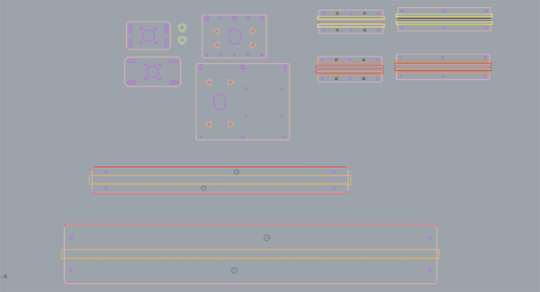
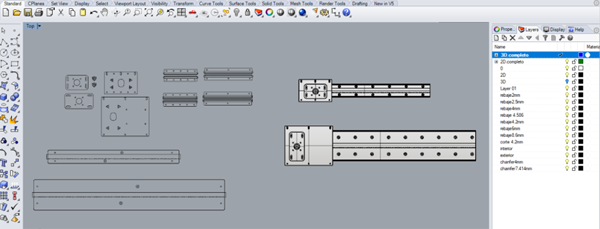
We imported the .dxf file into the CNC software and following the steps of the 8th week:
1. First we checked that we didn't have any open or duplicated vectors.
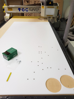
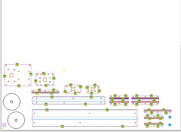
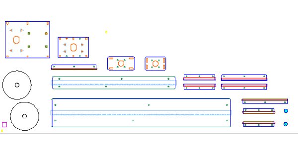
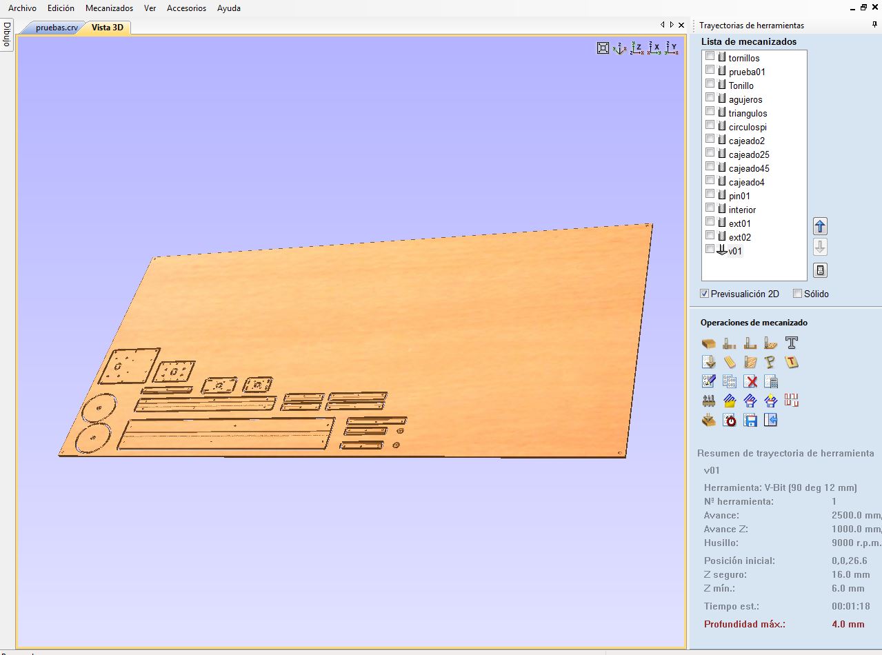
2. Then we started to place the objects to be milled in the material as can be seen in the next picture.
3. Once we finish displaying them we checked that the distances between them were right specially between the ones that we were going to use the V-bit tool.
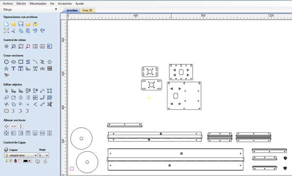
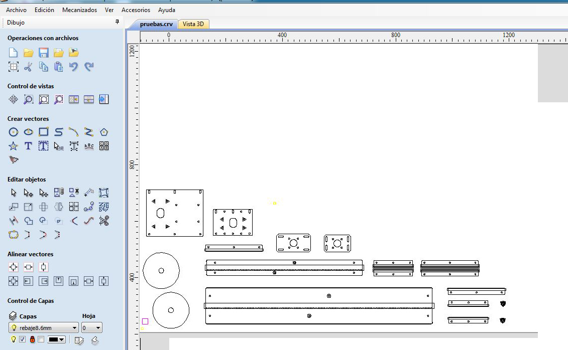
4. To plan the trajectories we spliced the different cuts in different layers as was explained before, trying to set them in the order that we were going to mill them.
Tools
We used four different tools:
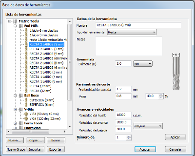
2 mm Endmill Up-Cut double-flute
| Tool diameter | 2 mm |
|---|---|
| Depth of the cut | 1.2 mm |
| Step | 0.8 mm |
| Spindle speed | 18000 r.p.m |
| Feed Rate | 2880 mm/min |
| Plunge Rate | 400 mm/min |
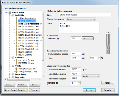
3 mm Endmill Up-Cut single-flute
| Tool diameter | 3 mm |
|---|---|
| Depth of the cut | 3 mm |
| Step | 2.04 mm |
| Spindle speed | 2400 r.p.m |
| Feed Rate | 425 mm/min |
| Plunge Rate | 200 mm/min |
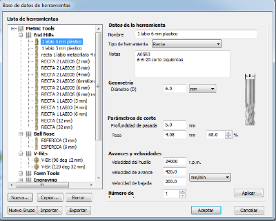
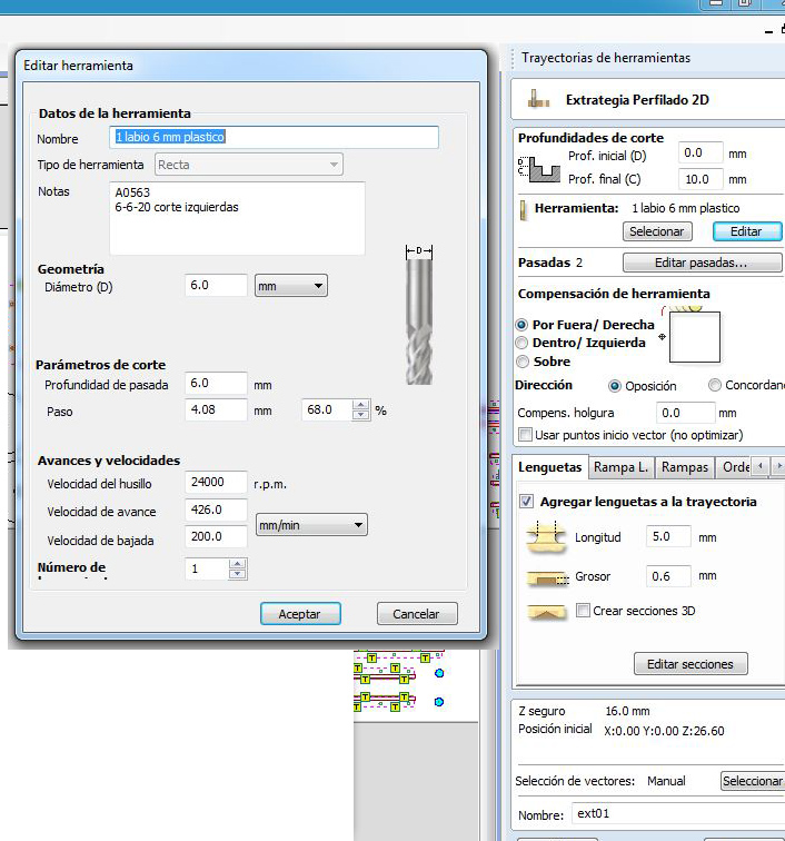
6 mm Endmill Up-Cut single-flute
| Tool diameter | 6 mm |
|---|---|
| Depth of the cut | 6 mm |
| Step | 4.08 mm |
| Spindle speed | 2400 r.p.m |
| Feed Rate | 426 mm/min |
| Plunge Rate | 200 mm/min |
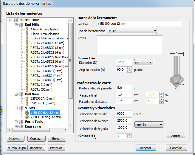
V-bit 90 deg 12 mm
| Tool diameter | 12 mm |
|---|---|
| Angle | 90 º |
| Depth of the cut | 5 mm |
| Final cut | 1.2 mm |
| Roughing cut | 1.2 mm |
| Spindle speed | 9000 r.p.m |
| Feed Rate | 2500 mm/min |
| Plunge Rate | 1000 mm/min |
A. Drilling with 3mm tool:
The first trajectory that we described was the inside holes as we used them to fix the pieces to the sacrifice layer. As you can see in the pictures we have removed some of them as we were not going to use them.
B. Fixing the pieces to the sacrifice layer:
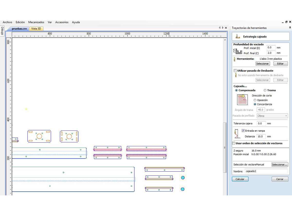
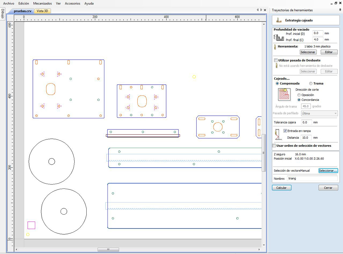
C. Pockets with the 3 mm:
We used the V-bit tool to do the different pockets that we needed for the racket and for covering the nuts. We had two types of pockets that needed to be done one of 2 mm depth and the other one of 4mm depth.
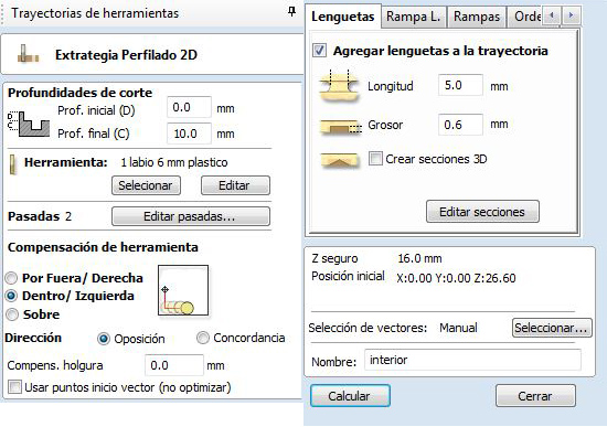
D. Profile path with the 6mm tool:
For milling the exterior of the pieces we used the 6mm tool. We created a new trajectory, setting the outside milling type and selecting the tool that we wanted. Like in the interior case, we used ramps. We selected the exterior parts of all the pieces and we saved this trajectory.
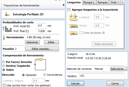
E. Profile path with the V-Bit tool:
We used this tool to do a chamfer on the sides of the rail and glidebocks.
F. Milling the pinion with the 2mm tool:
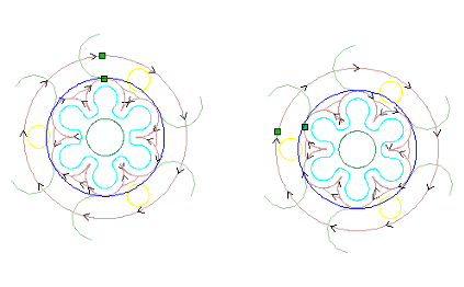
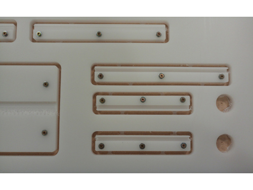
The resulting trajectories looked like this:
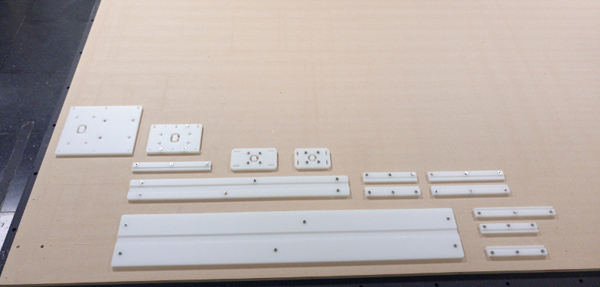
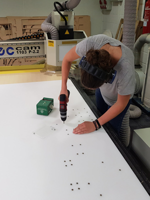
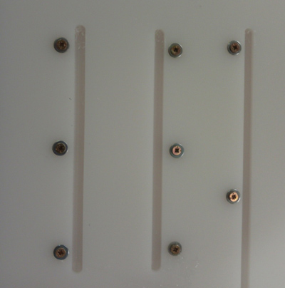
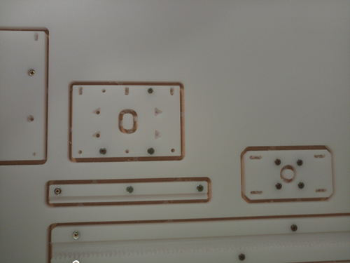
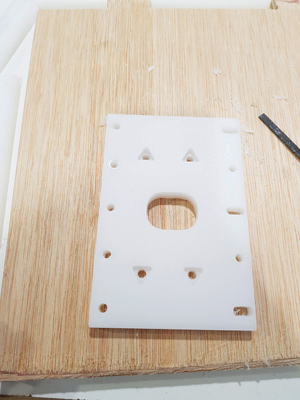
Removing the pieces from the base:
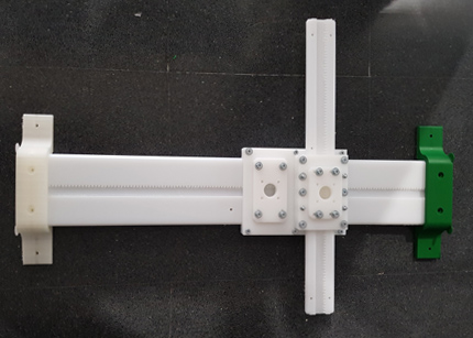
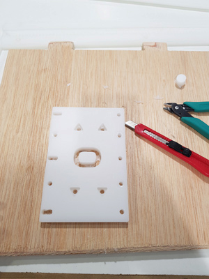
Assembly
Once we had milled all the axis pieces we started to assembly them. We had to remove the tabs of some of the pieces:
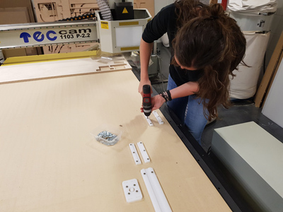
Join the different pieces together
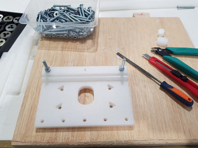
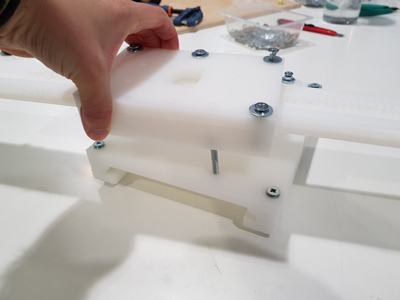
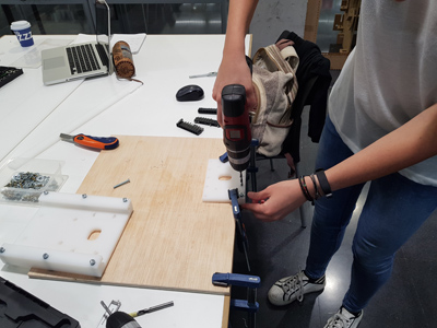
We also did some extra holes that we didn't do when doing the trajectories as they were the ones that conform the union between both axis. We wanted this union to be coiled. First we attached the pieces to be milled manually to the base, then we drilled the corresponding holes and then we coiled it.
Resulting chamfer rail: