Input device
Things to do:
2) Measure something: add a sensor to a microcontroller board that you have designed and read it
Have I achieved this week's goals?
Distance Sensor
Thanks to the Embedded programming week, I understood the importance of input and output roles. For this week, I started looking for the different kind of sensors. I paid attention to all of them, but I was curious to try the distance sensor. I already tried to find useful information on its use and features. The user guide I looked at, was really well organized and gave me a complete idea about the sensor I wanted to use. Obviously, I also read some datasheet's sections here. Thanks to it and some quick information I googled, I understood the main difference between the HC-SR04 (the sensor I'm going to use this week) and the HC-SR05, that is an other version that has an OUT pin too. So, with the HC-SR05 you can link the OUT to the GND and in this way the pin related to the trig and the echo will work just in one pin. Doing so, you have the availability of an extra pin. Anyway I wanted know more about the sensor I would have been used. So, here's a quick sum up!
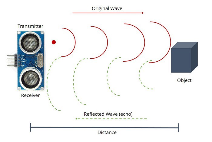
The ultrasonic sensor uses sonar to determine the distance to an object. Here’s what happens:
1) the transmitter (trig pin) sends a signal: a high-frequency sound
2) when the signal finds an object, it is reflected
3) (and) the transmitter (echo pin) receives it.
Before drawing my PCB, I looked at the Neil's one, because I'm a beginner in electronics field and I don't always have the awareness of needed component. In other words, I want to be sure to use the right ones. In addition, this week I read some paragraphs of ATtiny45 datasheet. It was the first time I used it and so, I had to know something more about its pins features. Moreover, I watched some video tutorials about the sensor I wanted to use. I've never seen it before and I had no idea about its characteristic. In fact, I discover which were the roles of TRIG and ECHO pins.
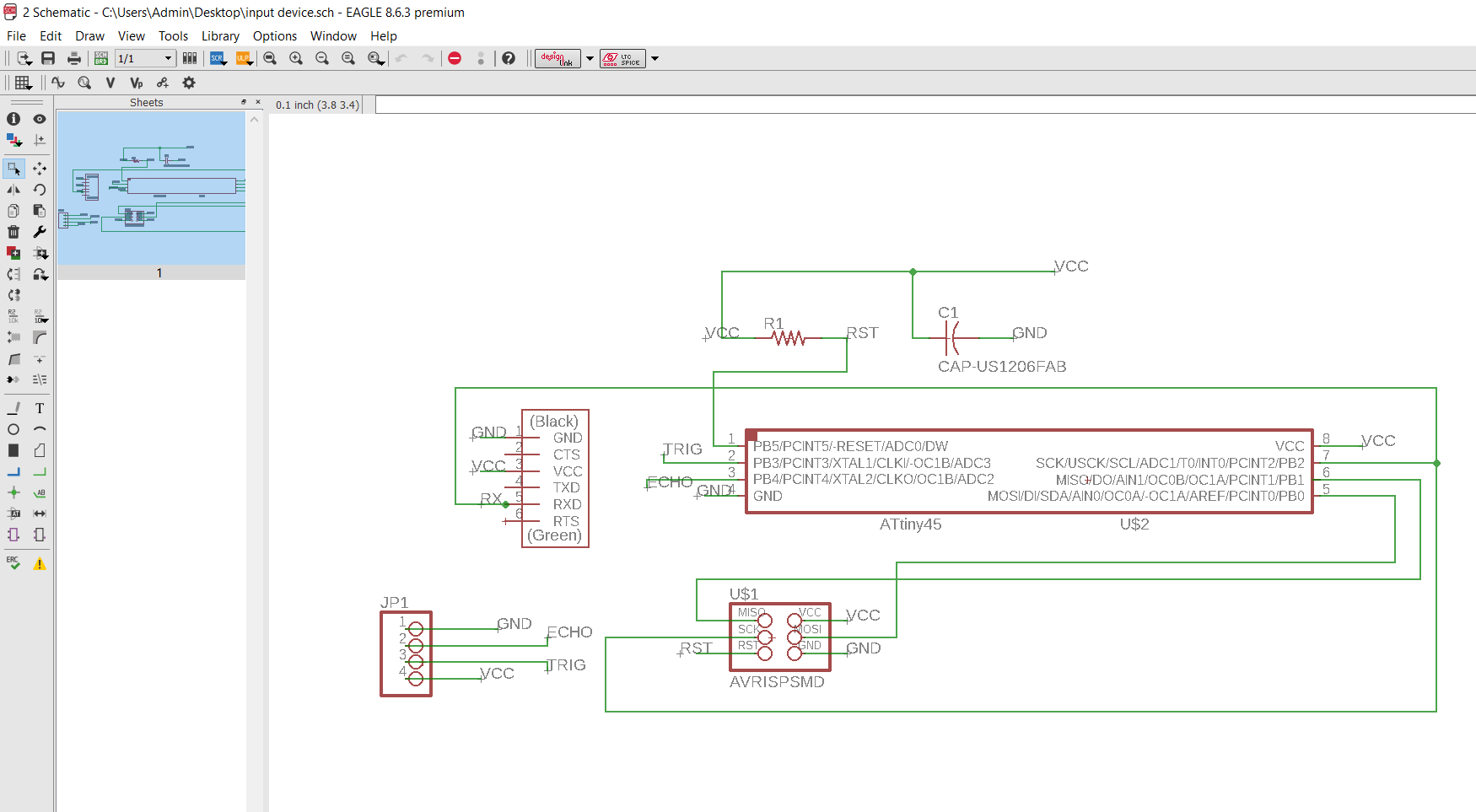
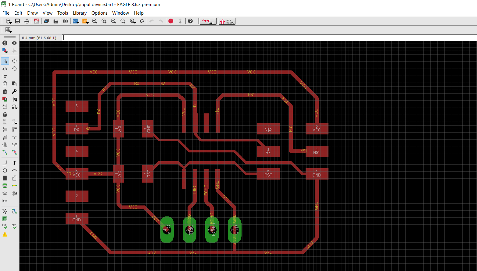
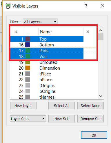
After this quick understanding, I started drawing my board on Eagle. I enjoyed my time working on it, because it's quite fun. In order to become more practical, I decided to do an effort: please, don't draw the green labyrinth of green lines! So, I tried using the labels where I can and when I feel sure about them, because I'm always scared to put off my stride! Then, when I started drawing the routes, I remembered and I noticed (thanks to the setting I did) I used a small width during the electronics design week. For this reason, I draw them on 16 mill (instead of 12). As a matter of fact, the board's design was better, but I had to pay lot of attention to the proximity of your traces. After having finished my board, I saved it clicking on Export ---> .png/.jpg and setting the following options (visible layers: top, vias, pad).
Then I started using Gimp to resize my file and to create three different files: traces, outline and drills (in this case because I have male pin headers 1x4).
Next, I opened Fab Modules to export my files in .rml extension and mill my board with the Roland.
When I downloaded the .rml file I didn't pay attention to my traces and only during the soldering (...obviously!) I noticed I drew two traces too near. So, when I started soldering the ISP I noticed it and for this reason I unsoldered it with the twist in order to remove some tin. After that, I used the hot air gun but...it removed the traces too. So, I had to mill and solder again my components before doing the test with the sonar. All I can do is to keep my finger crossed! What I did at this point? Obviously, I came back to the Eagle's board and I edited the traces that caused me the problem. Next, I exported again the file and I did the same procedures on Gimp and Fab Modules too. When my files were ready, I milled my board and I started soldering the components (I took them from the old one). Anyway, I tried the ready-made code (sonar.py) but when I tried to flash the program, I found rc = -1. At this point, I tried to use the multimeter and my board worked properly. So, I understood that the mistake was on the traces I did. I opened the schematic and I noticed that all was linked correctly. But, from the board's sight I saw that the PB2 and MISO weren't linked. I immediately went to the soldering station in order to create a jumper. Here's my board and its problem (finally) fixed!
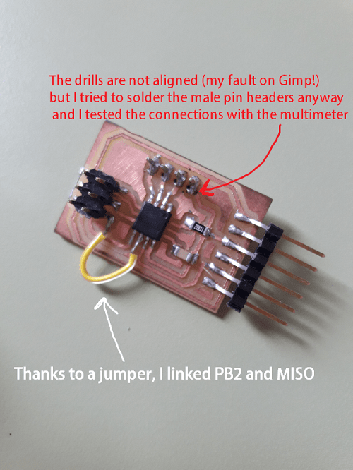
Doing so, I soldered both the extremities of my jumper to the PB2 and the MISO. After that, I decided to do a quick test with the ready-made code. I followed this procedure because I wanted to see how the sonar worked: it was an ordeal! Probably, at the expert's sight, this kind of situation could seem ridiculous but I'm really trying to do many efforts to understand things and to improve. Obviously, I learned a lot from my mistakes and this week (more than other times) I can say for sure..."you learn by your mistakes!"
The make file I tried first is available on this page. Then, I tried the following one via Arduino IDE and I connected my wires to the Arduino UNO in the following way:
Finally, I could watch the sonar working!
HC-SR04 sonar.mp4 from Eleonora Piccinelli on Vimeo.
Velostat / FSR
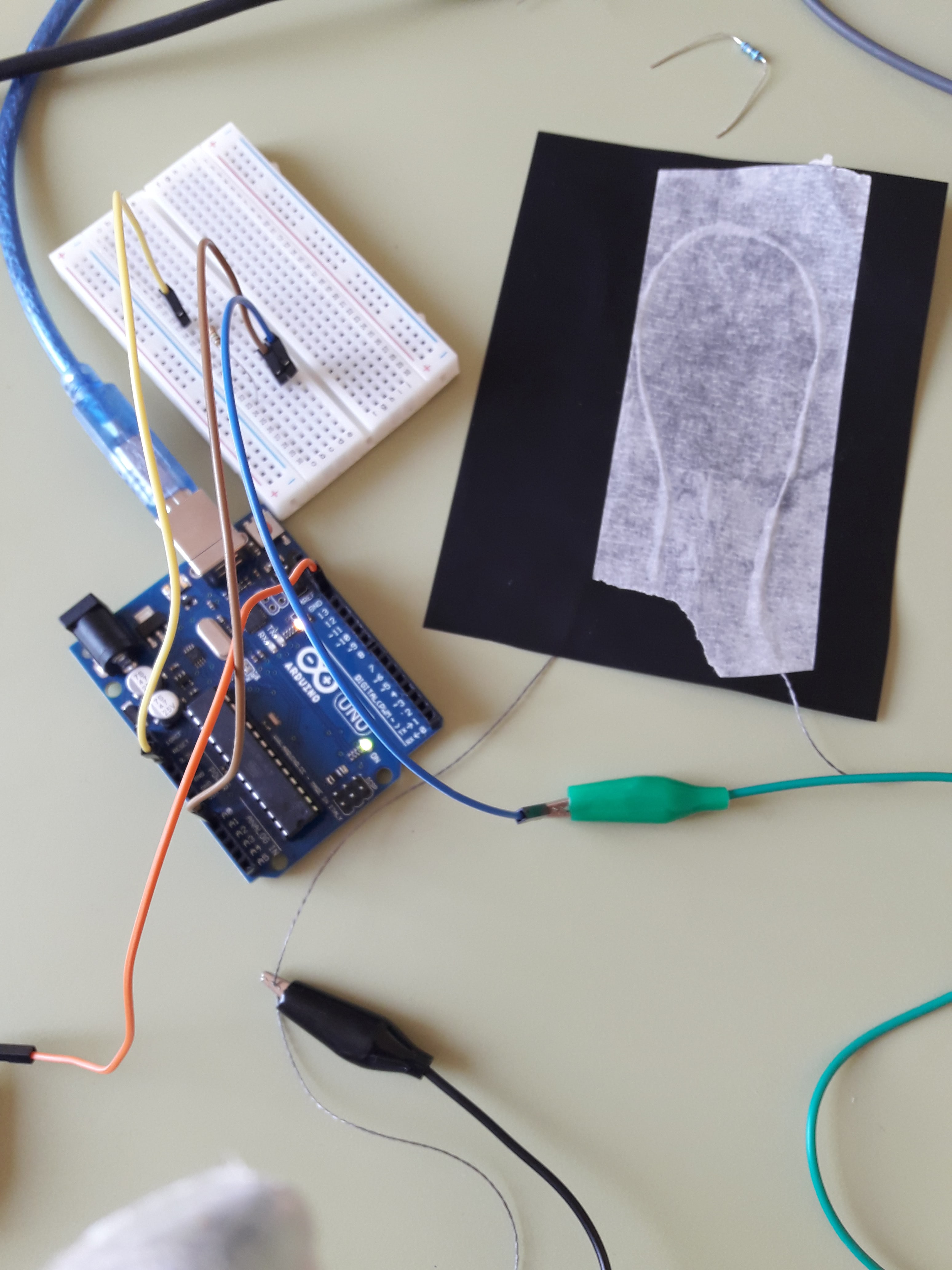
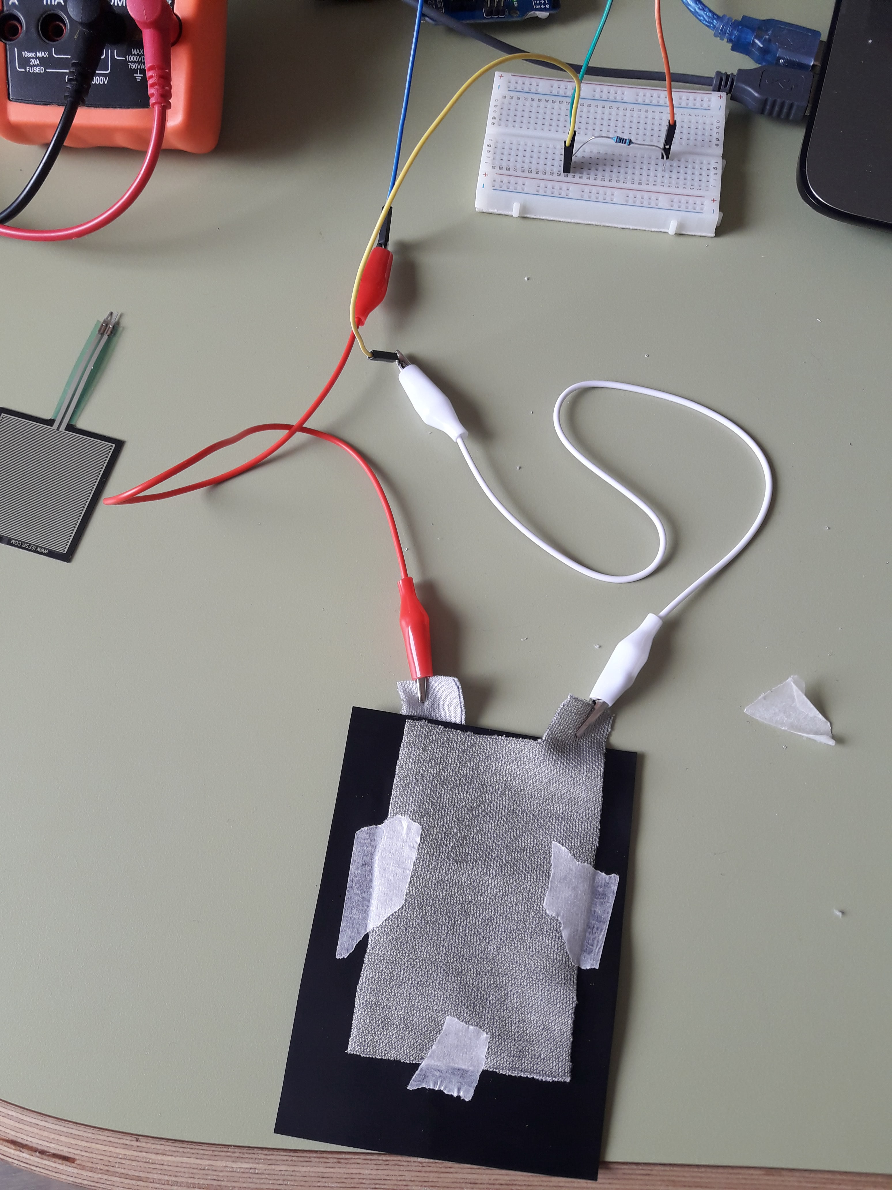
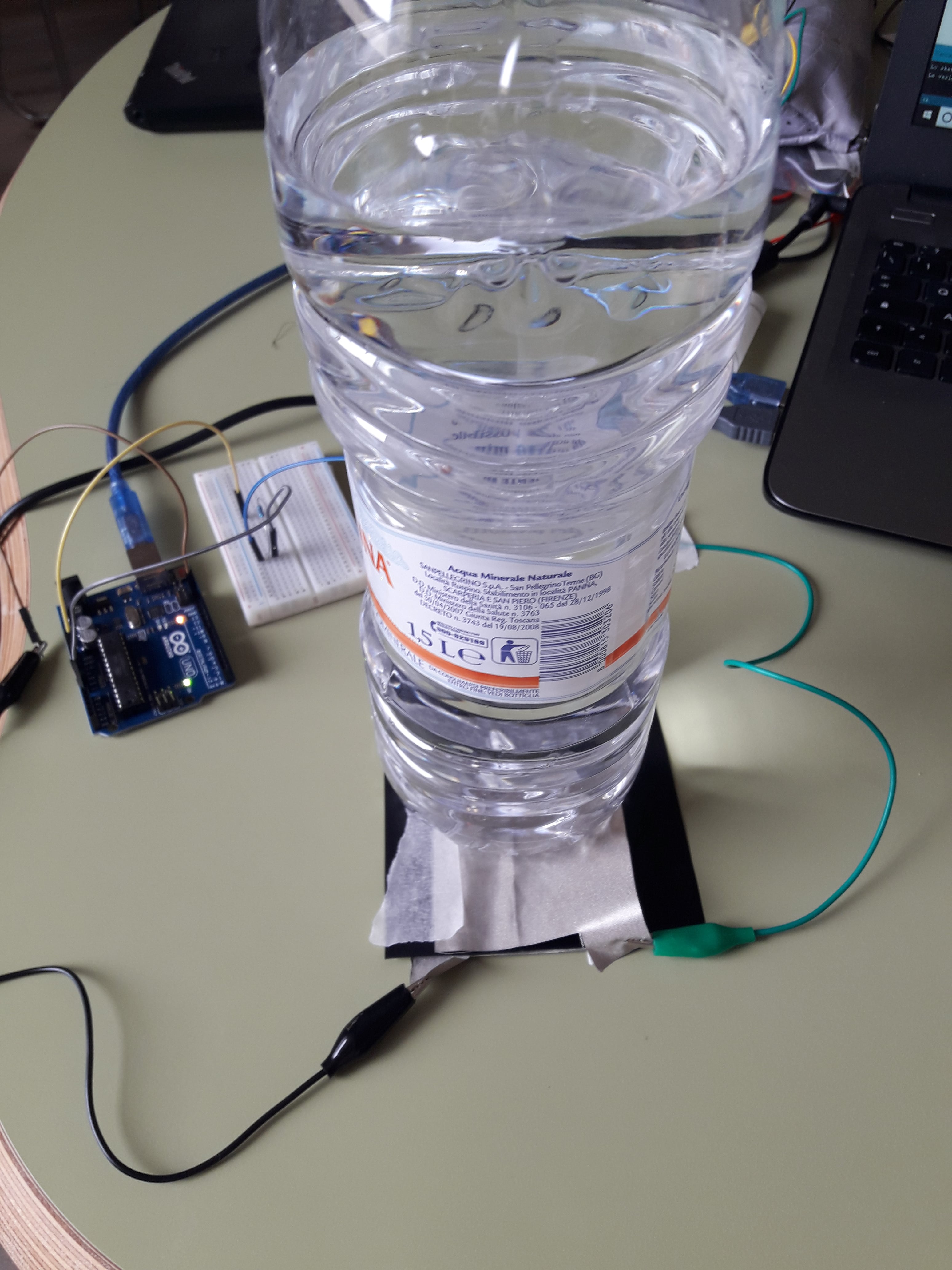
In order to increase my awareness in the field I've more lacks, I decided to update this section with the input device I used for my final project. Particularly, I needed a pressure sensor made of Velostat and conductive fabric. I linked it to my master board and I wanted to receive data from it (presence/absence of pressure).
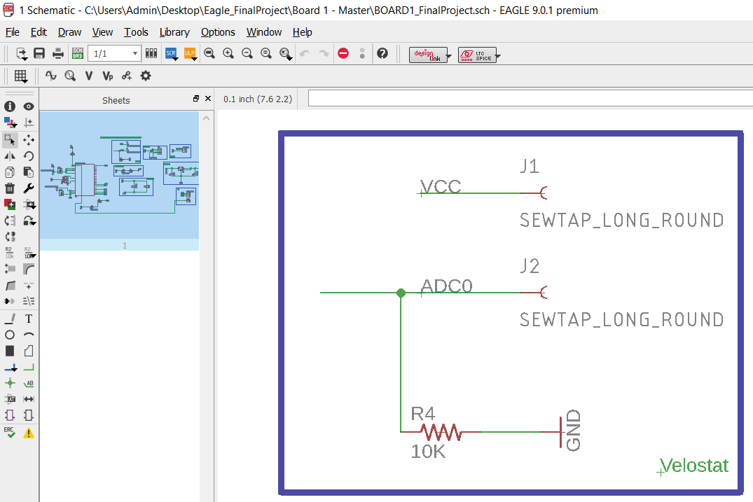
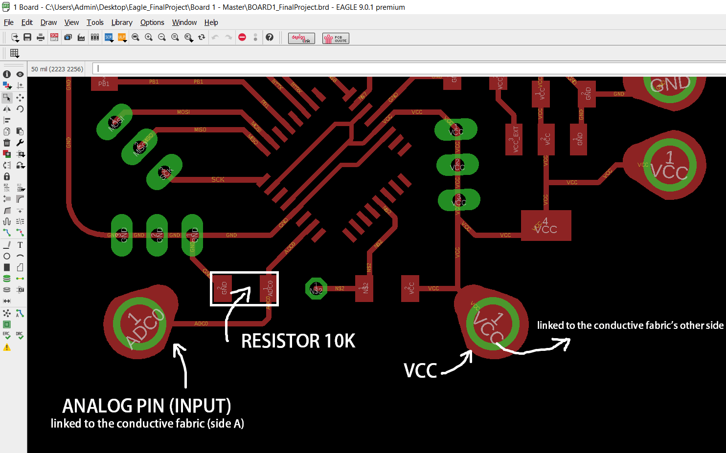
As you can see from the schematic, in order to connect the pressure sensor, I needed an analog pin. Consequently, I linked the latter one to a pad (installed by the Lilypad Library). My conductive thread would have been sewed around it and the sensor will represent an input device. On my PCB I used an ATmega328p and I looked for its datasheet. I connected the alligator clip to the VCC and to the ANALOG PIN. Basically, I did it because I wanted to respect the condition I had on my board. I programmed the board using the following options on Arduino:
I did some tries and I watched which kind of values I had on my IDE. To know more about them, please go to the final project section. To do a quick sum up, I can just say the values were quite steady. As a matter of curiosity and after some tries, I wanted to know more about the FRS too. I wanted to know if its values were more precise or not. Not surprisingly, they were as I've imagined. And yet, in spite of everything, I needed Velostat for my final project and it allowed me to respect the functionalities I had in mind. It won't represent the last solution because it doesn't allow too much certainty.
 >
>
More than this, I did some tests and the first code I wrote to do some attempts (for both the input devices) is the following one:
Final code and pressure sensor's improvements are available here.
Useful links:
Distance sensorATtiny45 datasheet
HC-SR04 datasheet
HC-SR04 guide
HC-SR04 - Youtube
How to use the ultrasonic sensor trig pin
Velostat / FSR
ATmega 328p datasheet
Velostat features
FSR datasheet
Connecting an analog sensor to Arduino
