Electronics Production
Things to do:
2) Make an in-circuit programmer by milling the PCB (program it, so that you can use it to program your board in electronic design week)
Optionally, trying other processes.
Have I achieved this week's goals?
This week has been really amazing because the assignment's aim was related to electronics field and the creation of an In-System Programming (ISP) board . I looked for some information and I chose to recreate the FabOptimus2 electronic board. First of all, I downloaded the traces and the outline and I saved them on my desktop. Then, it was necessary to convert the images in a different extension (readable by our SRM-20 Roland Machine). So, I opened the Fab Modules site and I followed the actions below.
ATTENTION!
Remember that the Roland Machine (SRM-20) engraves what is in black and leaves what is in white.
For this reason, pay attention and reverse the image color on the modules if is necessary.
Preparing traces and outline
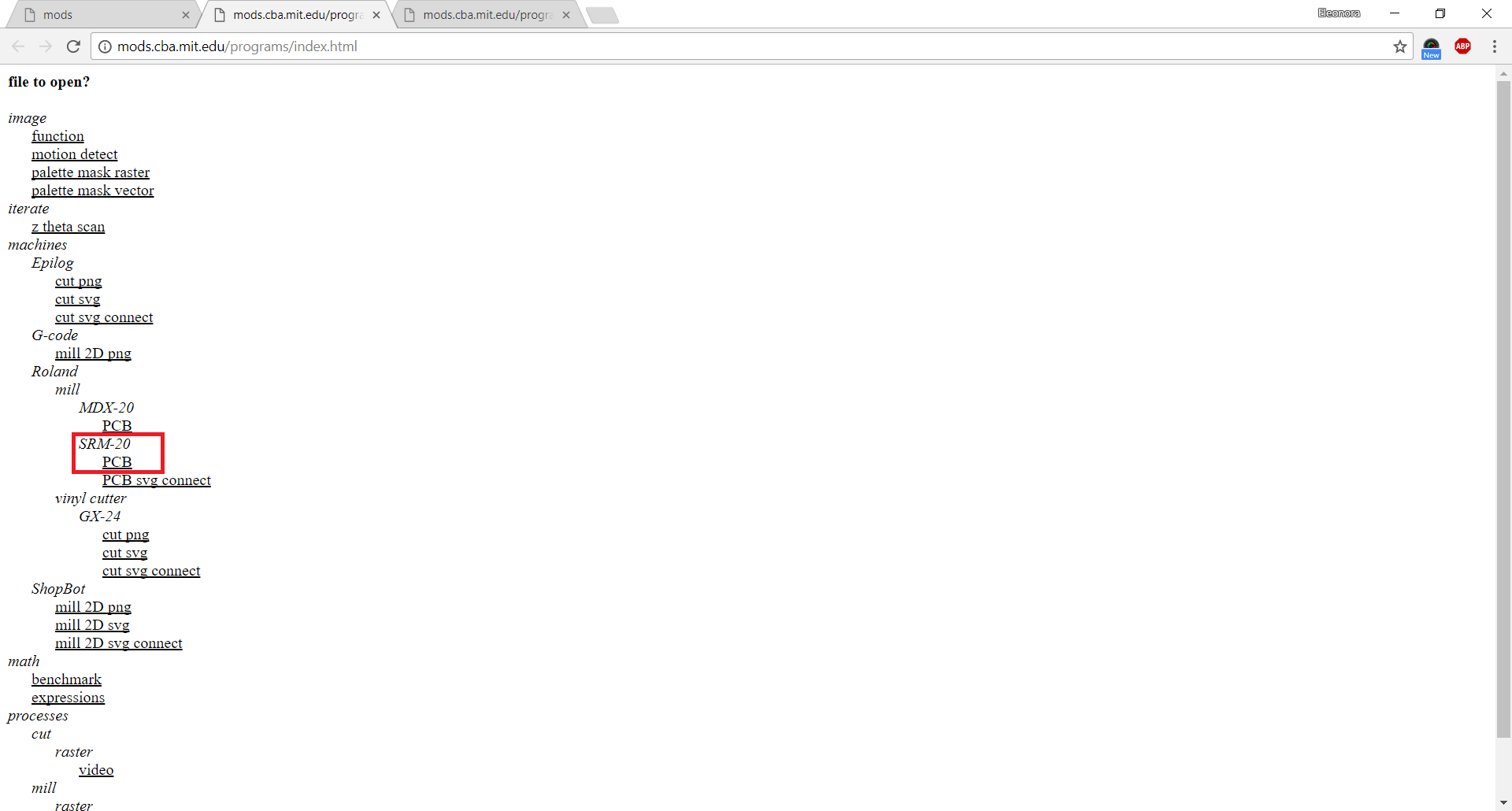
1) Program--> Open server program --> Machines --> Roland --> mill --> SRM-20 --> PCB
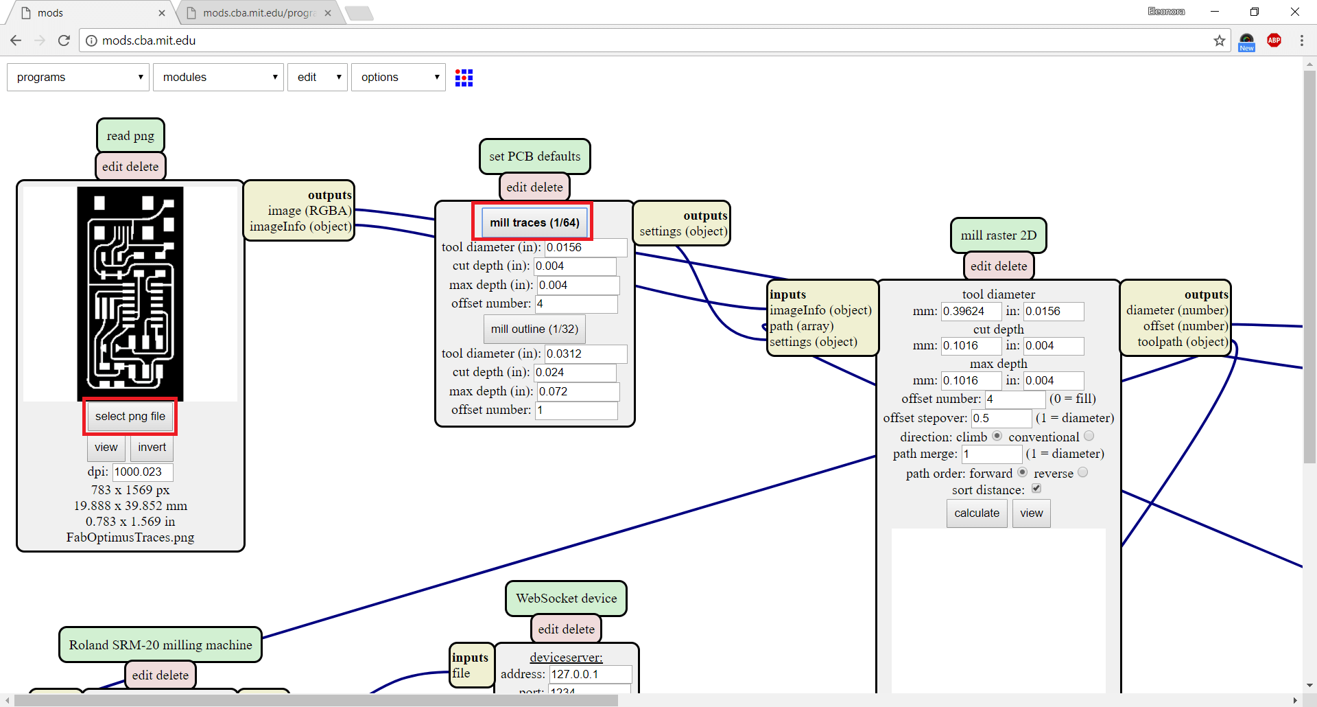
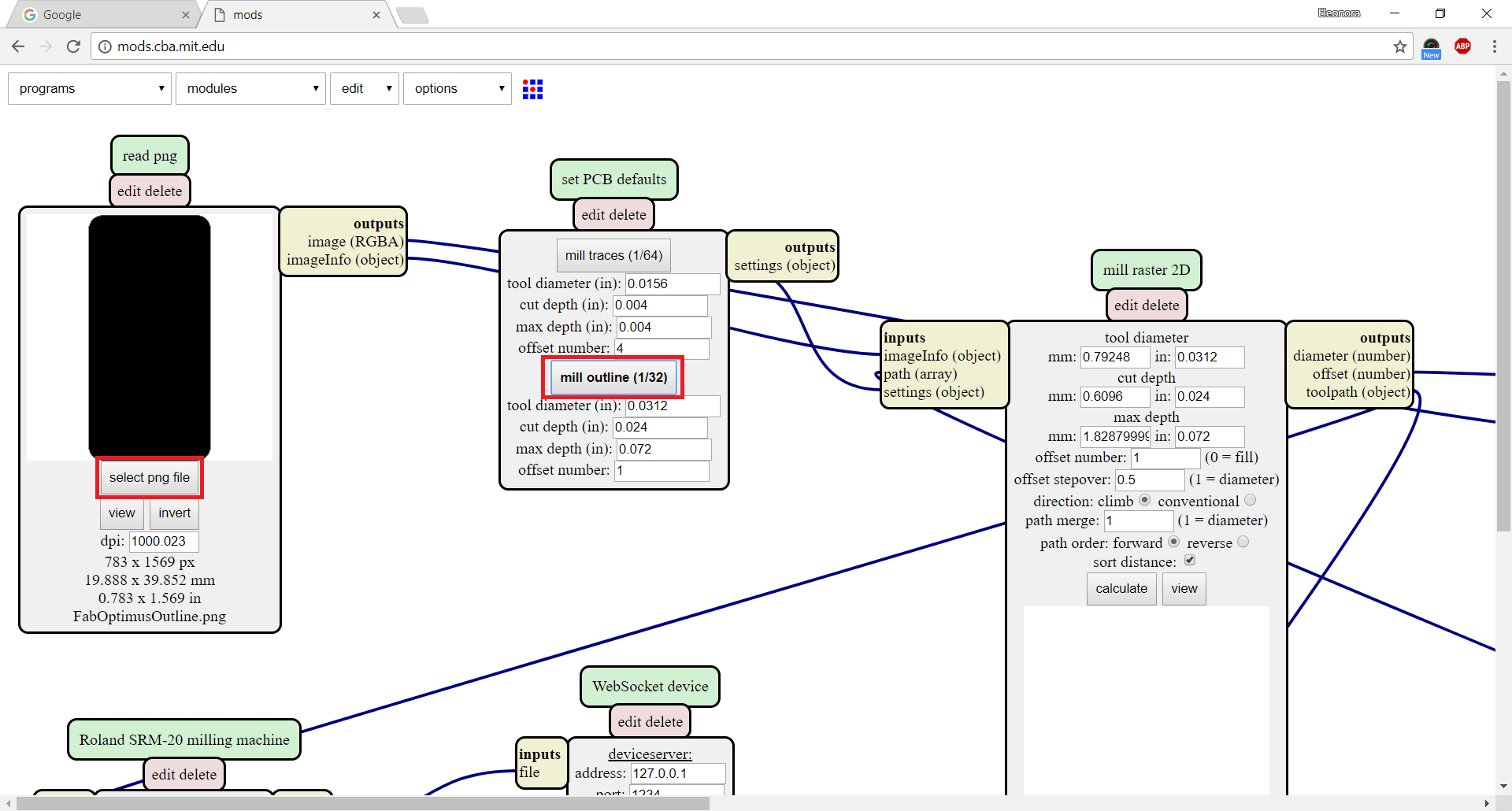
2) Next, I uploaded the traces file I saved on my desktop (.png extension). Here, is important to follow some main actions:
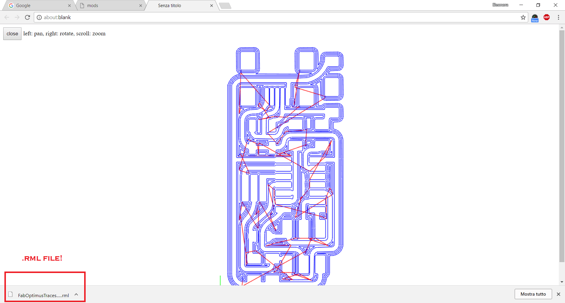
3) Then, I clicked the right mouse button and I chose Module --> open server module ---> FILE --> SAVE (it allows you to generate the .rml file and to mill the PCB. In other words, the .jpg you saved on the computer and you uploaded on the Fab Modules, will be converted and saved (in the download's folder) as an .rml file (language's machine!)
4) Finally, I clicked on CALCULATE and the system downloaded the .rmlextension automatically. As I said few lines above, now I was ready to mill!
5) I repeated the same steps to obtain outlines .rml file. The only thing you have to keep in mind is related to the option under the MILL RASTER 2D. In fact, this time you have to use a different tin: the outline needs the 1/32. Excepting this thing, the other passages are the same. Consequently, I followed the same actions I described.
Roland SRM-20 and VPanel
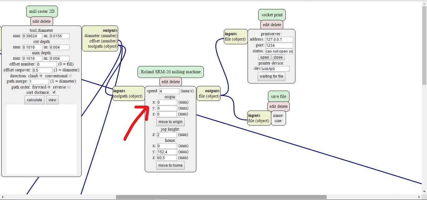
After that, I went to the Roland Machine and I connected my USB pen. At this point, I learned to set the right values in order to mill my first board! You have to give the origin to X, Y and Z axis. The VPanel you find on the computer is very useful and well organized. It shows all the sections you need to know:
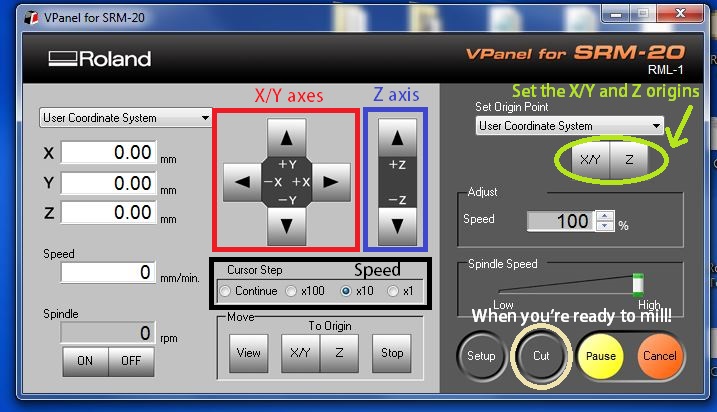
The screenshot below shows the panel that controls our Lab Roland SRM-20. Before starting, you must remember the most important things:
For example, when you're next to the plate with the milling point, it is recommended to use a lower speed instead of the "continue" option.
In other words, I moved the cutter in the starting position I wanted and when I was sure about it, I set it as the origin starting point (X and Y axes). After, I did the same thing to set the Z axis. To do that, I moved the axis really slowly in order to touch the copper plate delicately (that's why I recommended to use a lower speed to move the axis). Right now, I could press on CUT option, but there are some things to looked at before starting the milling process. In fact, I followed the actions I highlighted in the screenshot below:
DELETE ALL to clean the files listADD to upload the .rml fileOUTPUT to mill the board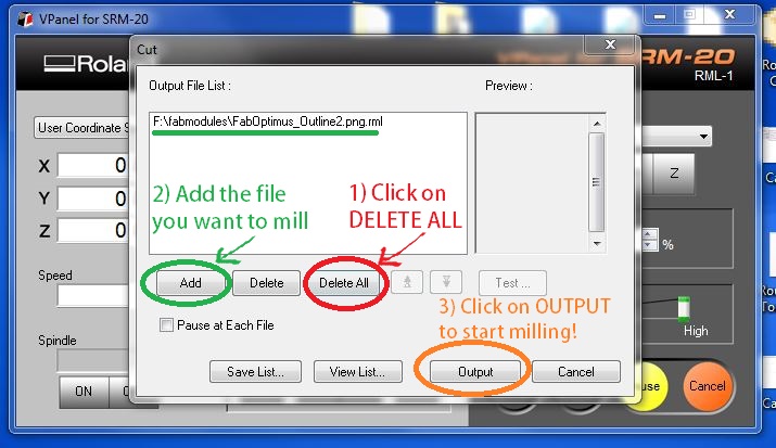
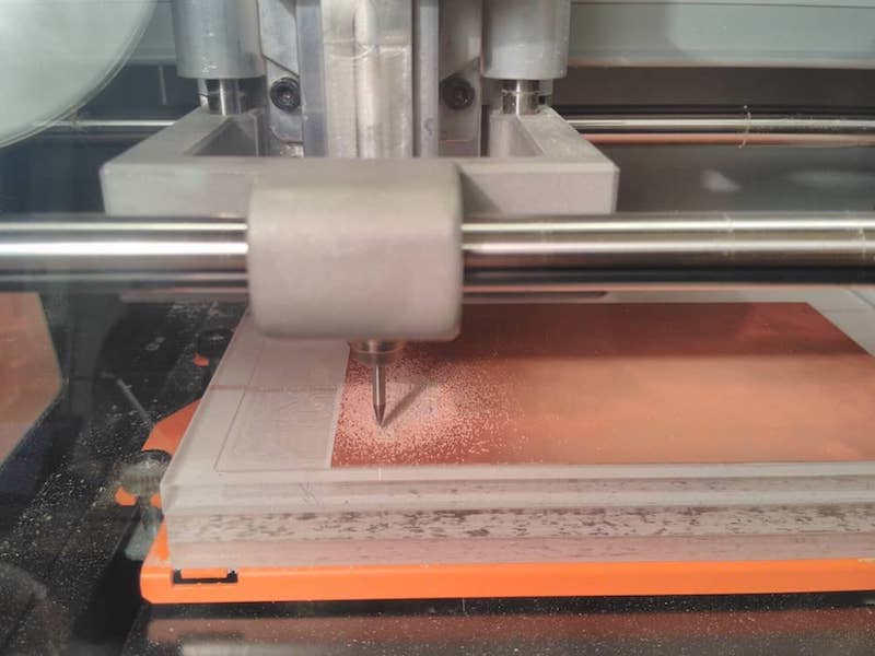
Wait and repeat the same workflow to mill the outline using the 1/32 tip!
N.B: When you have chosen the tip (1/64 to mill the traces and 1/32 to mill the outline). Don't forget to bring the essential tools in front of you and the machine. Our instructor suggested us to keep the desk clean and tidy. Doing so, you avoid the risk to lose some tools or using the wrong tip!
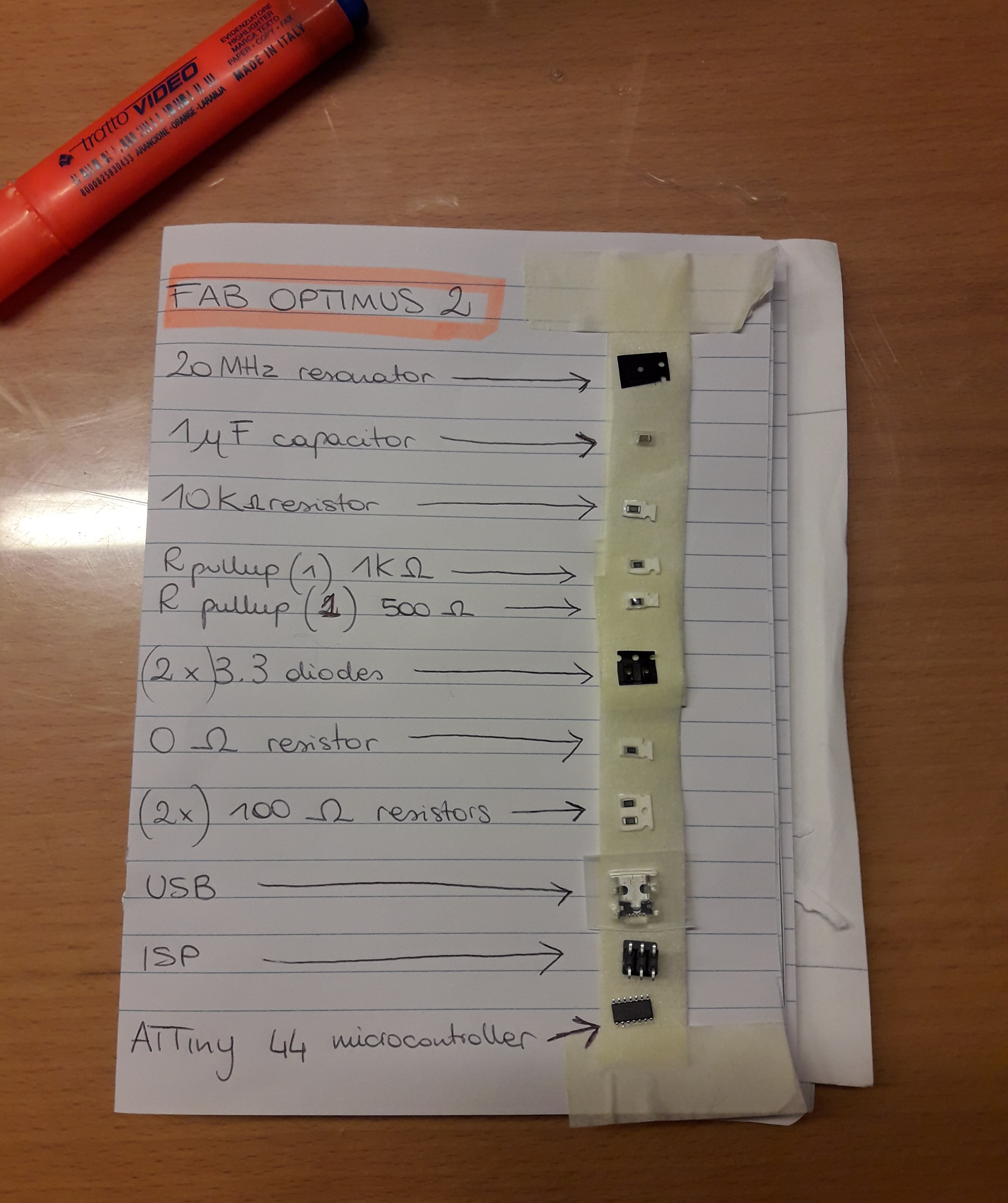
Bill of materials (BOM)
What is the bill of materials? It can also be called BOM and it is a simple list of the needed components. Basically, I looked for them inside my Lab and the following list will explain which ones I needed:
Soldering
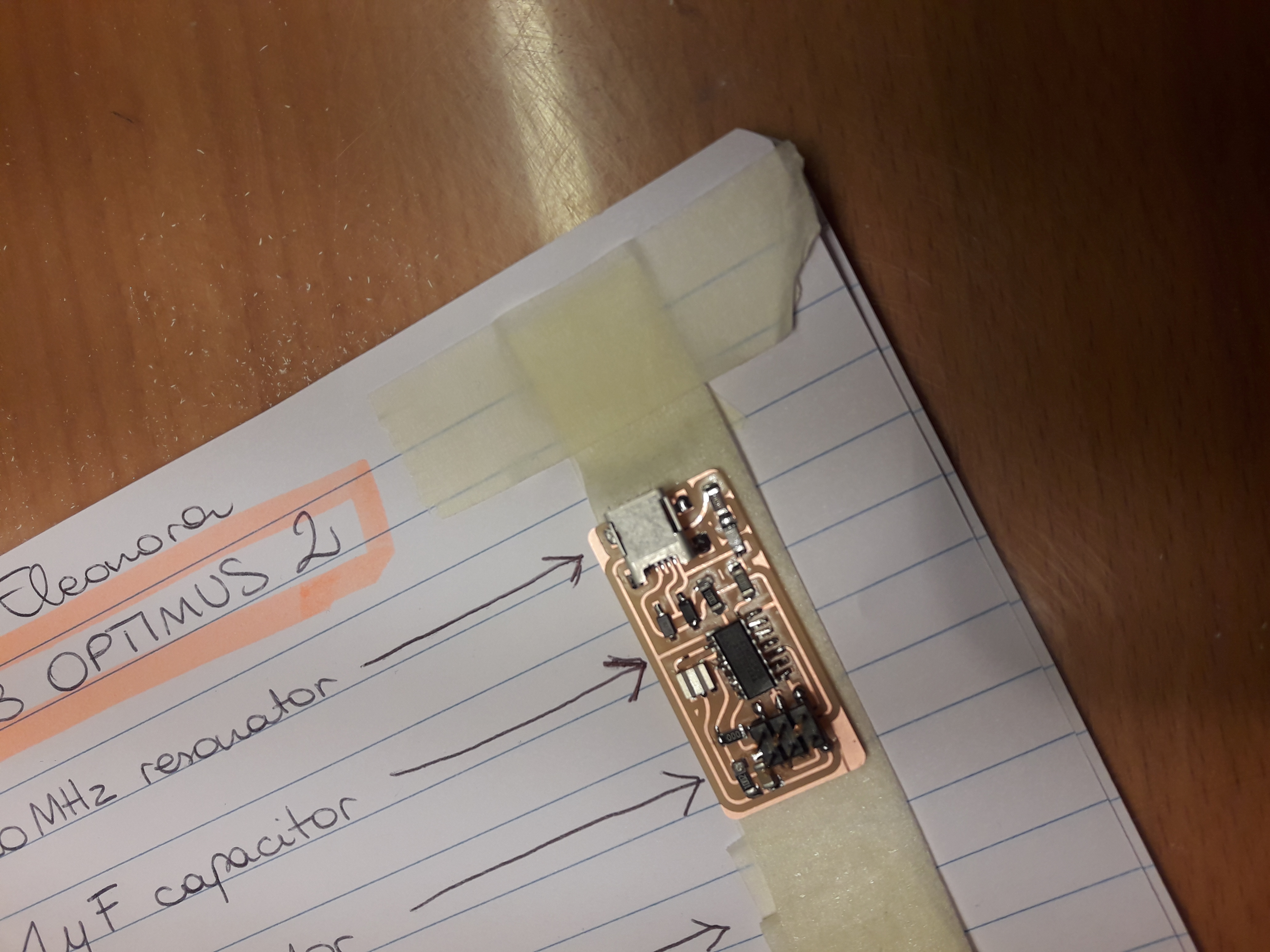
I really enjoyed my time in soldering. I've never done it before. Even if it's a demanding activity, it gives you the right satisfaction! The essential thing before starting is: don't be hurry! You need time and patience, especially if you work with micro electronics elements. Don't touch the soldering iron and try to be precise. It's easy to describe the action in worlds, but it's quite complicate soldering for the first time. My first test wasn't too bad, but I moved the ATTiny 44 (microcontroller) during the soldering operation, so it wasn't straight with the traces. My board will never work! In the picture below, you can see the problem I had: the microcontroller is not aligned with its traces. Consequently, the tin put under the pins was completely useless!
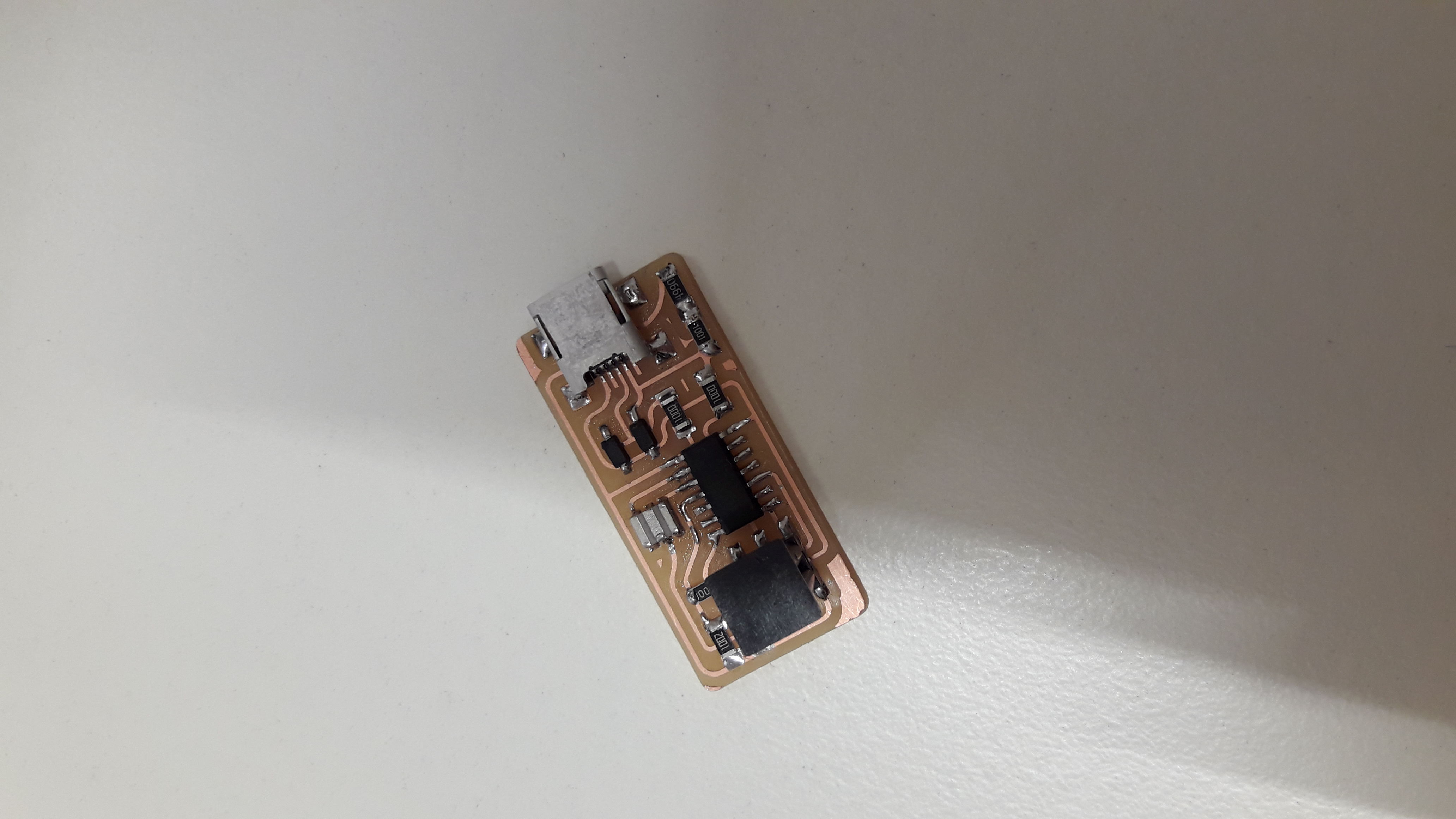
So, I decided to try again, because I needed a bit of practice and I would notice the difference with the last one. I simply did the same board paying attention to all the components. I followed a precise order in order to soldering them without too many difficulties. Anyway, I noticed it was really complex keeping the component unmovable in the right place: the electronics part are really small! It has been challenging and I put myself on the line: I started working on a sunny morning with a background music. The result was good! :)
Programming
After being alienated with the soldering activity, I programmed my FabOptimus board. I listened to my classmates guidelines and I noticed I was obliged in using a different operative system from mine. So, I tried to start my programming session with Linux on Tommaso Lombardi laptop. Before starting, we did the test on our boards and everything was fine. His board would have been my programmer, but unfortunately, after the first steps on Ubuntu Terminal, typing the first action related to make fuse, we noticed an error. Where was the problem? We bad linked our boards. What does it mean? Boards must be linked correctly with the right direction of VCC and GND. In other words, each GND pins on the ISP must correspond to the other board's GND and so on. When we realized our mistake my board was already programmed with with MacOs operative system. The second try has been a beginner's lucky?! I can say that was, because I noticed all my mistakes after having done them.
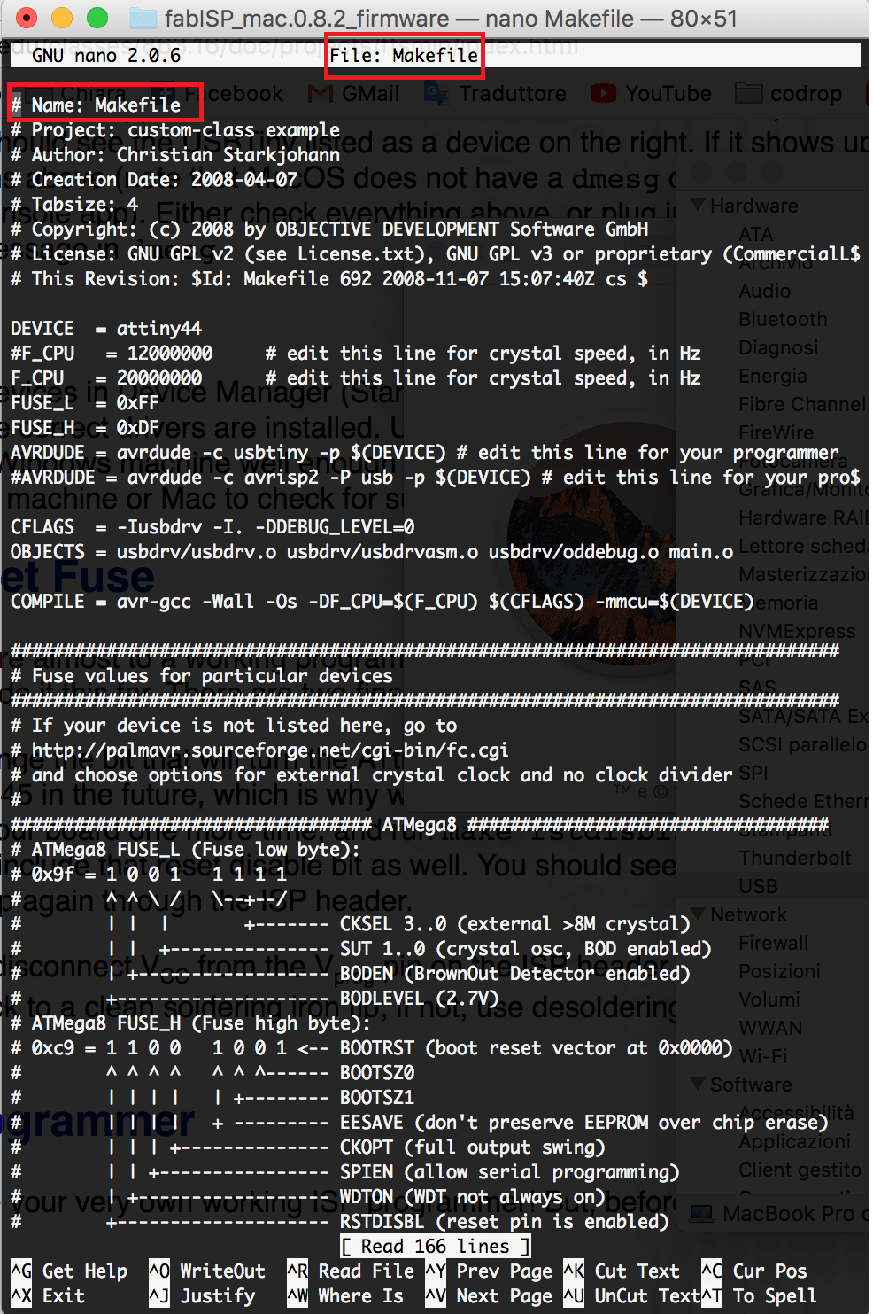
In order to program my board, I followed the guidelines written here, but, I'd try to summarize the main steps in a few passages.
First of all, I opened the MakeFile with the TextEdit on the computer and I wrote the passages written on the webpage I linked.
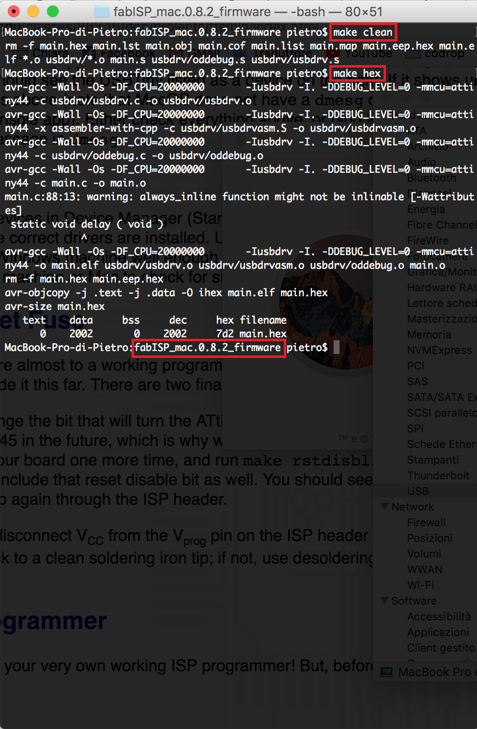
1) make clean
2) make hex
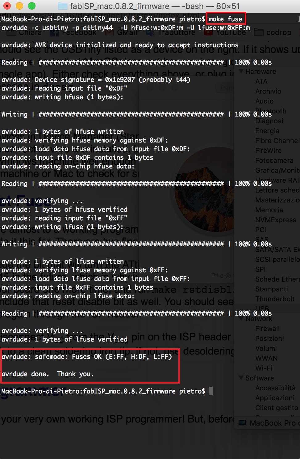
3) make fuse
The commands I mentioned above were only three, but their meaning was much more complex. That's why I tried to better understand what do they mean.
source code. After that, it builds the hex file (that is the essential machine code!) Fortunately, I found this useful webpage that explains it very well!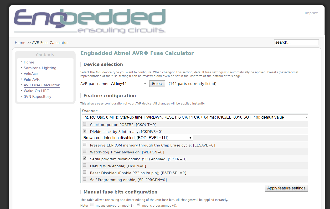
As you can see, I just set the microcontroller I had on my PCB, but the webpage didn't help me a lot...because it was Greek to me! So, I read the ninth chapter of Make AVR Programming and only after, I can say that fuses are simply related to the microcontroller's clock speed. So, my convintion to be aware of MCU properties was correct, but now I have to study a lot to better understand its features.
hex file you created before. After that, it will be uploaded into the microcontroller.If you got errors, check this page! Even if I programmed the poard without any kind of trouble, I checked it because I thought something wouldn't have gone right.
After having programmed the board, remove the 0 Ohm resistor and solder bridge. Only doing this, you can use it as a programmer to program other boards. It is an essential step, otherwise you'll do the same mistake I did! I thought my FabOptimus didn't work properly :D ... In other words, I pretended to program other boards without having soldered the resistor! After having understood my mistake, I unsoldered the jumper and my board became ready to be a programmer.
Useful links:
Fab OptimusFab Modules
Fab ISP Programming
