Week 12: Output Devices
Group assignment:Measure the power consumed by a Output Device
Individual assignment: Add an output device to a microcontroller board you've designed, and program it to do something
In this week we need to add an output device to the microcontroller and do something on that, I plan to make LCD Display board that displays the atmospheric temperature and pressure.
Now I am going with the design a new board for output week, From Neil's lecture I heard about sastha kit. So this week I was going to design a board using atmega328p.
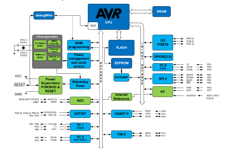
High performance micro chip developed by Atmel .It is a 8bit AVR RISC-based microcontroller combines 32KB ISP flash memory with read-while-write capabilities, 1024B EEPROM, 2KB SRAM, 23 general purpose I/O lines, 32 general purpose working registers, three flexible timer/counters with compare modes, internal and external interrupts, serial programmable USART, a byte-oriented 2-wire serial interface, SPI serial port, a 6-channel 10-bit A/D converter (8-channels in TQFP and QFN/MLF packages), programmable watchdog timer with internal oscillator, and five software selectable power saving modes. The device operates between 1.8-5.5 volts.
Here i am using TQFP package . Pinout diagram is shown in below
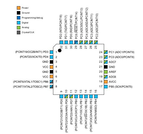
Here I choose Atmega32p TQFP package; it mainly has 8channel 10 bit it ADC, Flash memory of 32 k and EEPROM of 1K, and 23 general purpose input output line, it consists of 2 8-bit Timer/Counters and one 16-bit Timer/Counters
The device is shipped with internal RC oscillator at 8.0MHz, and with the fuse CKDIV8 programmed, resulting in 1.0MHz system clock. The startup time is set to maximum, and the time-out period is enabled: CKSEL=0010, SUT=10, CKDIV8=0. This default setting ensures that all users can make their desired clock source setting using any available programming interface.
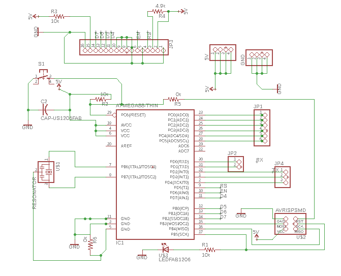
Open the eagle softawre and draw schematics shown above .I plan to add an LCD directly to board and also give header pins to for using other pins to connect with any sensor you want, Also make some extra VCC and Ground.
A 20Mhz resonator connected across the XTAL1 and XTAL2 pins, Rest is pulled up using 10k resistor series with VCC, also join push button to rest pin and another pin of the switch is grounded. Atmega 328p already has the 8mhz internal clock. A clock is essential for the working of a microcontroller. It helped to execute the codes sequentially. We usually connected Crystal oscillator is used to provide a clock to micro-controller. The clock is used to carry all the function that microcontroller offers. Crystal connected across the XTAL1 and XTAL2, add the load capacitances from the pins to ground. I used Resonator instead for Crystal oscillator because it already has capacitors inbuild.
A 22uf capacitor connected across the VCC and ground ( avoid the ripples -ripples may cause the improper working of the microcontroller).Led is connected to digital pin 13. ISP pins are connected to MOSI, MISO, SCK and Reset pin. 16 pin header is provided to connect the LCD. The connection diagram for LCD referred from referred from This link
Complete the schematics next go to eagle board design part in which I give 16mm clearance and 18mm width.
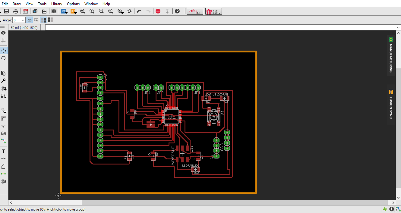
After design the pcb in eagle and export the traces, dimension and dill paths separately, save it as png ( use monochrome mode to export the images )
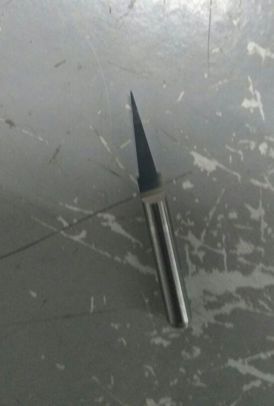
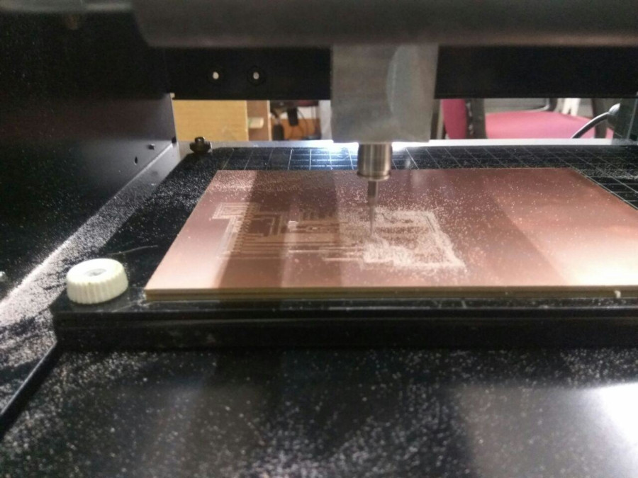
After opening the traces image in mods and choose use 1/64 bit to mill the pcb.while drawing the traces I give 16mill as the trace width.in our lab has 0.25mm () V bit) for milling the pcb while giving the tool bit diameter 0.25mm it shows a good tool path. Set offset to 3 and kept other settings by default.
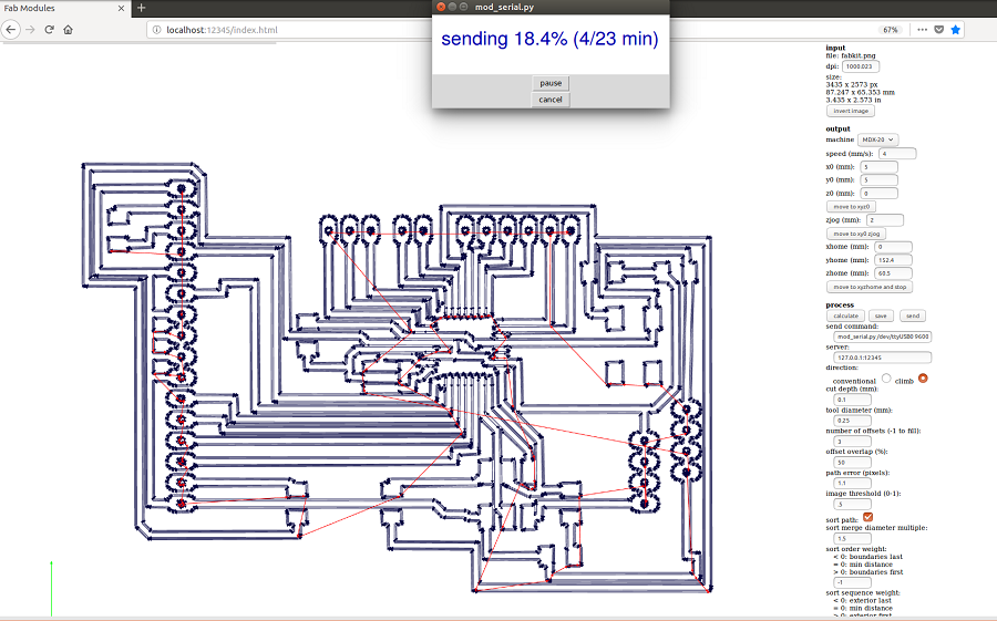
After milling the traces then i replace the 0.25mm bit with 1/34mm bit and first perform the drill and then perfrom the cutting function finally i got my pcb.
Next i go to soldering stage its quite interesting , soldering atmega 328p to pcb is quite hard ,first i solder one leg and then flow the other
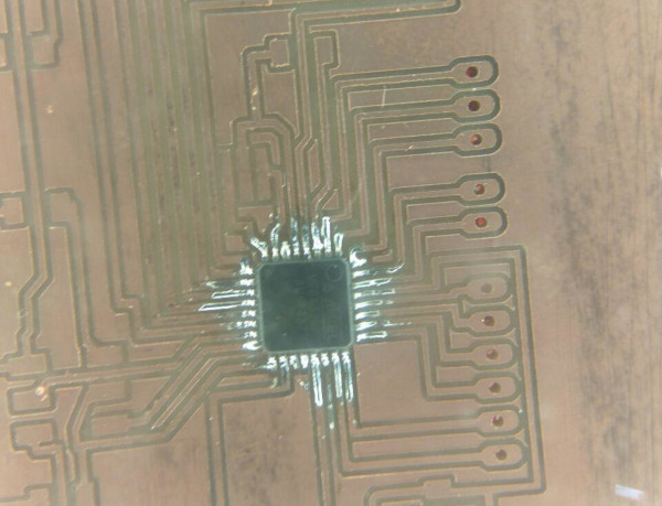
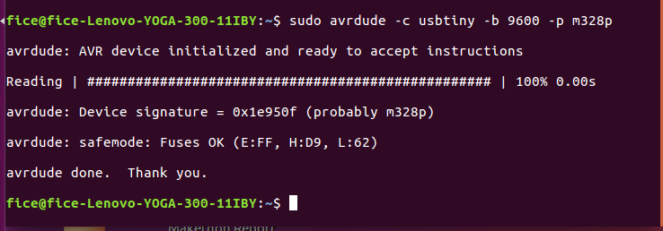
After soldering the components i checked the board using avrdude command and it shows the board is working good.
Here I am providing an external clock of 20khetrz, Running the device on an external clock, the CKSEL Fuses must be programmed to '0000':
Configuring Arduino IDE
I am planning to program the microcontroller using Arduinoo IdE so i need to add few settings in Arduino Ide environment to make programming.I am using different clock frequency and IC package is differnt from that of Normal Arduino Uno so i used to follow the MCUDUDE mini core to make such changes in my arduino IDE : Mcdude Mini core package .
Steps for Installing MiniCore
- Open the File > Preferences menu item.Enter the following URL in Additional Boards Manager URLs:https://mcudude.github.io/MiniCore/package_MCUdude_MiniCore_index.json
- Tools > Board > Boards Manager... menu item -enter MiniCore search panel and click on it.
- Click Install:After installation is complete close the Boards Manager window.
After installing the mini-core package in Arduino IDE, Next, I need to burn the fuse, which means that I connect 20khz resonator with the Atmega IC if I don't burn the fuse it doesn't use that 20khz only uses the internal clock. So first i burn the bootloader using Arduino IDE.
Next i check the board using sudo avrdude -c usbtiny -b 9600 -p m328p and it show a Atmega 328p is working fine
LCD 16x2 Display Module :
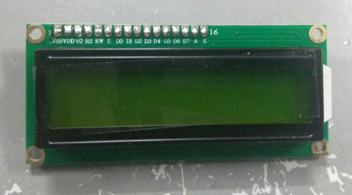
LCD is the technology used for displays in notebook ,smaller computers and small devices .16x2 LCD means it means it has 16 Columns and 2 Rows.there are various combinations available in the market mainly 8x1, 16x4 etc.
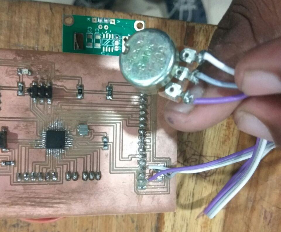
VCC is the source pin that is used to give supply to lcd, VO pin is used to adjust the contrast of lcd we need to connect it with a variable pot that can source 0-5V.RS/RW Toggles the LCD between Read/Write Operation ,this pin are connected to Microcontroller pin and gets either 0 or 1. 0 for command operation and 1 for read operations.EN pin sange for enable, it must be held high to perform Read/Write Operation
D0 to D7 are Pins used to send Command or data to the LCD. LCD module has 15 and 16th pins that are used to connect a led to illuminate the LCD, we need to add a 1o k resistor serious with 15 pin and then connect to 5v otherwise led may tends to damage.
Details are taken from this source
Using arduino ide we can easily interface the lcd with microcontroller board.we can use Lcd in 4 bit mode or 8 bit mode in four bit mode we can only use any of the pins from Do to D7.In 8 bit mode we need to use all the pins from D0 to D7
Inside arduino IDE,There is a library allows microcontroller to control LiquidCrystal displays LCDs based on the Hitachi HD44780 or a compatible chipset, which is found on most text-based LCDs. The library works with in either 4- or 8-bit mode using 4 or 8 data lines in addition to the rs, enable, and, optionally, the rw control lines.
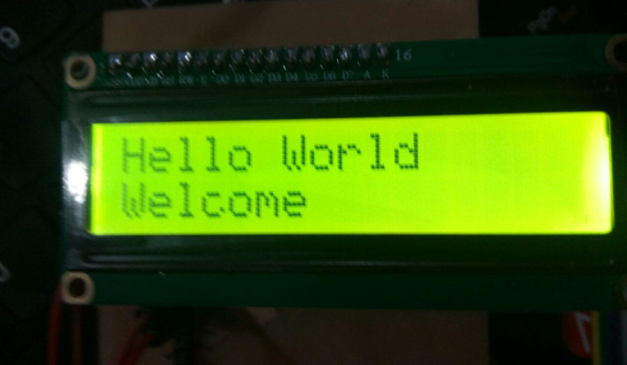
Sample code that i run in lcd to perform test function
// Copied from Arduino exapmles //edited by amith gopkumar : April 10 2018 #include// call the library const int rs = 5, en = 6, d4 = 7, d5 = 8, d6 = 9, d7 = 10; //intialise the pins LiquidCrystal lcd(rs, en, d4, d5, d6, d7); /* Create object named lcd of the class LiquidCrystal */ */ For 4-bi mode */ void setup() { lcd.begin(16,2); /* This function is used to define the numbers of rows and colums the LCD has and to intialize the LCD. */ } void loop() { lcd.setCursor(0, 0); /* This function positions the cursor of the LCD to a location specified by the row and colum parameters.*/ // set location to 0 coloum and first row lcd.print("Hello World"); /* print dataa on display*/ lcd.setCursor(0, 1); // set location to 0 coloum and second row lcd.print("Welcome "); }
After writing the code , uploaded it to the microcontroller board but it does not shows the display output , so i need to check the connections .I made a simple mistake in oder to control the contrast of lcd ,instead of using a pot i used 4.9k resisistor to connect vo and vcc pins , so i remove the resistor , and connect a 10k pot between vcc, ground and vo pins of lcd . Now it shows the display what i need to print on LCD module.
Output Shown in LCD
After writing the code , uploaded it to the microcontroller board but it does not shows the display output , so i need to check the connections .I made a simple mistake in oder to control the contrast of lcd ,instead of using a pot i used 4.9k resisistor to connect vo and vcc pins , so i remove the resistor , and connect a 10k pot between vcc, ground and vo pins of lcd . Now it shows the display what i need to print on LCD module.
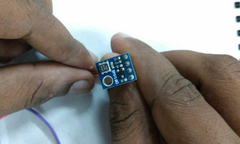
Next i go with BMP180 sensor module
BMP180
BMP180 is a low cost sensing solution for measuring barometric pressure and temperature.Pressure varies depends on attitude and weather. This sensor comees with I2C interface.BMP180 modules have 4 pins VCC, GND, SCL,SDA These pins are connected to 5V, GND , A4 and A5 pins of microconntroller board that i designed .I used jumper wires to made the connection with board.
Source from this information got
I2C
I2C is communication protocol that allows to allow multiple “slave” digital integrated circuits or chips to communicate with one or more master chips.I2C requires a mere two wires, and those two wires can support up to 1008 slave devices. I2C can support a multi-master system, allowing more than one master to communicate with all devices on the bus
Each I2C bus consists of two signals: SCL and SDA. SCL is the clock signal, and SDA is the data signal. The clock signal is always generated by the current bus master; some slave devices may force the clock low at times to delay the master sending more data or to require more time to prepare data before the master attempts to clock it out.
In order to work with bmp180 we need to add the library , Libraries are collections of software functions geared towards a single purpose, such as communicating with a specific device. Library for communication BMP180 sensor can be download from sparkfun website.
After installing the library i test BMP180 with test code and its work fine and i got the values
Details are taken from this source
My work
First i connect LCD to Microcontroller board that i designed , in which RS,EN. D4,D5,D6,D7 pins are connected to digital pins 5,6,7,8,9,10 .
SCL and SDA are theI2c pins of BMP 180 sensor it is connected with I2C pins of atmeaga 328p A4 (SCL) and A5 (SDA)
Code
// code is take form spakfun BMP180 Library
// Rfer: https://learn.sparkfun.com/tutorials/bmp180-barometric-pressure-sensor-hookup-/installing-the-arduino-library
// edited by Amith G container:11 April 2018
//
#include <LiquidCrystal.h>
const int rs = 5, en = 6, d4 = 7, d5 = 8, d6 = 9, d7 = 10;
LiquidCrystal lcd(rs, en, d4, d5, d6, d7);
#include <SFE_BMP180.h>
#include <Wire.h>
SFE_BMP180 pressure;
void setup()
{
lcd.begin(16, 2);
Serial.begin(115200);
Serial.println("REBOOT");
if (pressure.begin())
Serial.println("BMP180 init success");
else
{
Serial.println("BMP180 init fail\n\n");
while(1); // Pause forever.
}
}
void loop()
{
char status;
double T,P,p0,a;
status = pressure.startTemperature();
if (status != 0)
{
delay(status);
status = pressure.getTemperature(T);
if (status != 0)
{
lcd.setCursor(0, 0);
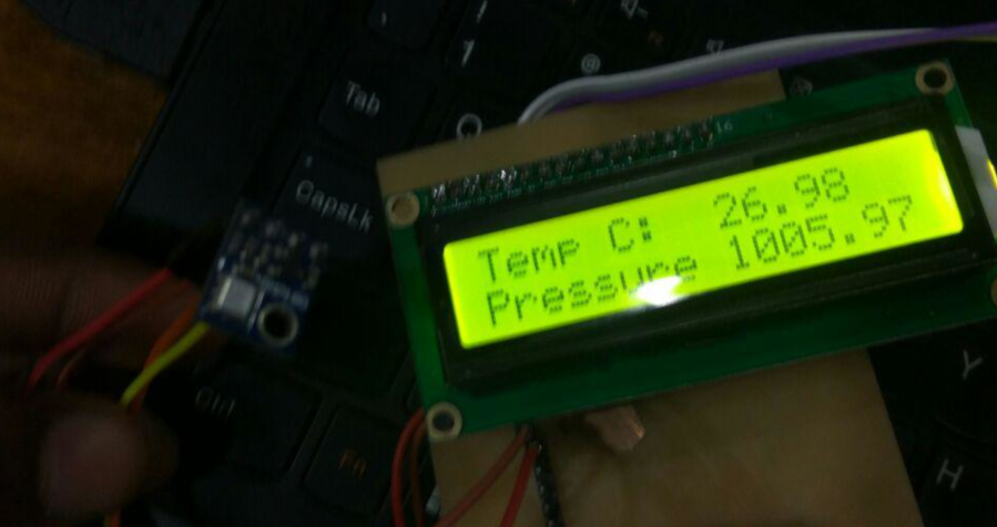
lcd.print("Temp C: ");
Serial.print("temperature: ");
Serial.print(T,2);
lcd.setCursor(9, 0);
lcd.print(T);
Serial.print(" deg C, ");
status = pressure.startPressure(3);
if (status != 0)
{
delay(status);
status = pressure.getPressure(P,T);
if (status != 0)
{
lcd.setCursor(0, 1);
lcd.print("Pressure");
lcd.setCursor(9, 1);
lcd.print(P);
Serial.print("absolute pressure: ");
Serial.print(P,2);
Serial.print(" mb, ");
Serial.print(P*0.0295333727,2);
Serial.println(" inHg");
}else Serial.println("error retrieving pressure measurement\n");
}else Serial.println("error starting pressure measurement\n");
}else Serial.println("error retrieving temperature measurement\n");
}else Serial.println("error starting temperature measurement\n");
delay(5000); // Pause for 5 seconds.
}
Output
Group Assignment
Here we need to calculate power consumption of a output device. We choose a motor to do the same. Dc motors are not connected directly to microcontroller boards.W e use Motor drivers to connect it with a microcontroller.
microprocessors operate at low voltages and require a small amount of current to operate while the motors require a relatively higher voltage and current. This current cannot supply to the motors from the microprocessor. This is the primary need for the motor driver IC.
Here we are using L239D motor driver module to control small Dc motor.L239D motor driver is a small Current Amplifier whose function is to take a low-current control signal and then turn it into a higher-current signal that can drive a motor.Power the motor
Motor need large amount of energy, cheap and local motors it goes high .
- Voltage Requirement:Here we used motor is only run at voltage between 8v to 12 V.
- Current:Norammly L239D can supply current of 0.8A tp 1.2A ,
We connect a 9v battery with motor it consumes current of 0.8A, That why we dont connect motor it directly to MCU with out using driver