Menu
HomePrinciples and Practices
Project Management
Computer-aided Design
Computer-controlled Cutting
Electronics Production
3D Scanning and Printing
Electronics Design
Computer-controlled Machining
Embedded Programming
Molding and Casting
Input Devices
Output Devices
Interface and Application Programming
Networking and Communications
Mechanical Design
Machine Design
Wildcard
Applications and Implications
Invention, Intellectual Property, and Income
Project Development
Final Project
Week 12
Output Devices
Week Assessment :
Add an output device to a microcontroller board you've designed.
and program it to do something
This week continues with the previous week which was Input Device week. I had to see the datasheet for Attiny 44.
Hashim did a session in how we select the right value for the resistor. We need a resistor to reduce the current flow. When the current change the brightness of led. If the current is high the LED will heat up and will burn.To find the value for resistor we had to apply Ohm's law.

we use Ohm's law which is V(volt) =I(amp)*R(ohm).
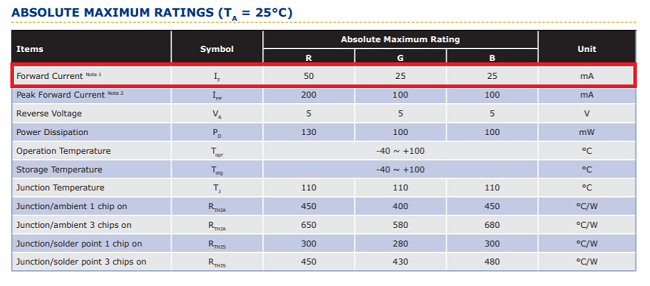
We can find the current which I(amp) in the datasheet of LED. Each LED has different current. This is how to find current from a datasheet.
Go to Fab Foundation → The Hardware and Software

Open Digi-Key website in another tab
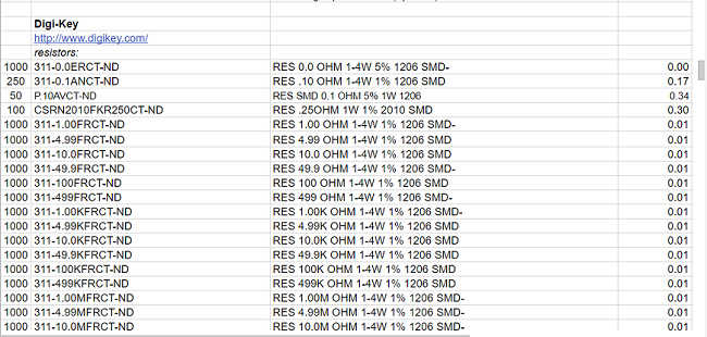
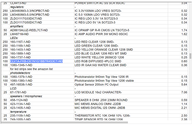
scroll down we will find all the component that we use in a lab.
I will pick this LED as an example, so copy the name of your component.
Paste in the search bar in Digi-Key → search

Open the datasheet
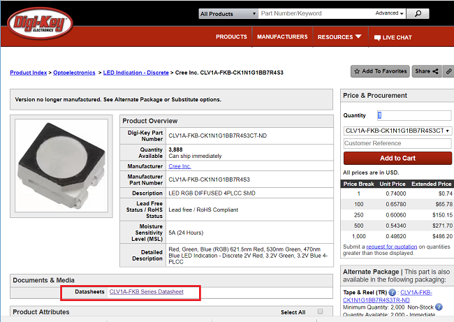
Here is the current and this is the maximum current
The second step is to find the voltage. If you used Attiny44 and the supply voltage 5V so the Attiny44 will not give exactly 5V for LED so we need to know the exact value of v which we can get from the datasheet
Attiny44 datasheetHere you can find a voltage. This voltage means that the minimum voltage for output high.
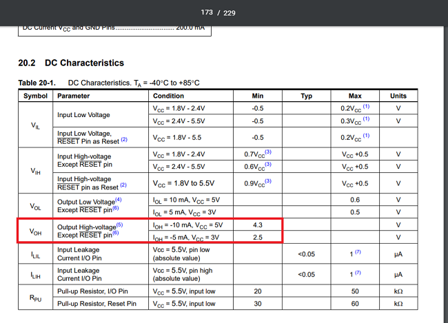
So the output high is between (5v - 4.3v) if the supply is 5v and (3v - 2.5v) if the supply voltage is 3v.
We have to apply ohms law or here is a link that will calculate the resistor value online. Not always will find the exact value of resistor so we pick the nearest value to be able to pick a resistor for breadboarding you need to know the color code resistors. While in SMD component they use digit code.
I used RGB LED as my output device. The reason why I chose RGB LED it because its related to my final project the output for my final project will be RGB LED strip. I used RGB SMD LED for now.
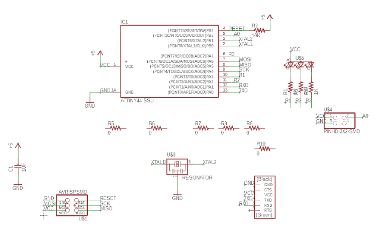
Anyway, I design my own output board with RGB LED. I used Eagle agine to design the schematic and PCB. There is some essential component I most have it in design like AVR ISP, FTDI, crystal and RC circuit connected to the reset pin in the microcontroller. The combination of resistor and capacitor called RC circuit.
Resistor & Capacitor
This from the datasheet for AVR microcontroller and I found really help. The RESET pin on the AVR device is active-low, and setting the pin low externally will reset the device. The reset pin does two things which are
1- Initialize all input and output registers and set the program counter (PC) to zero.
2- To activate programming mode means the microcontroller get ready to accept the program.
When the Attiny 44 turned on, the power may not be very stable. So the resistor and capacitor will keep Attiny 44 reset for a while until the power became stable. If there is no RC circuit connected to the reset pin. It may cause the ROM code to run abnormally.
Crystal
the device generates an oscillating signal of a specific frequency. used to provide a clock signal used to control timing in the microcontroller. every instruction is executed in synchronization with the clock. It provides timing for different operations in a microcontroller.
FTDI
Send any serial data back and forth including updating AVRs with a bootloader on them.
AVRISP
To connect the board to the program AVR programmer which is FabISP.
Then I add my component which are RGB LED and resistors and my sensor. I connected three resistors to limit the current in the LED to a safe value and the reason why I used three is there three LED inside RGB LED.
I connected Red to Port A 3 (PA3) in Attiny and Blue to Port A 2 (PA2) while Green to Port A 7 (PA7).
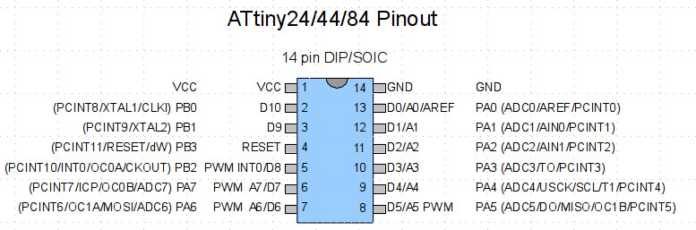
Like it shown in my schematic.
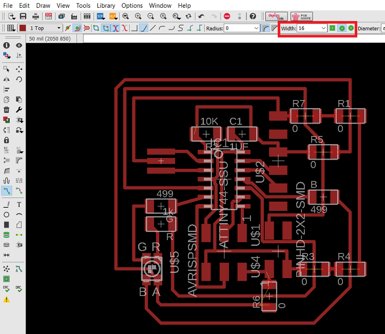
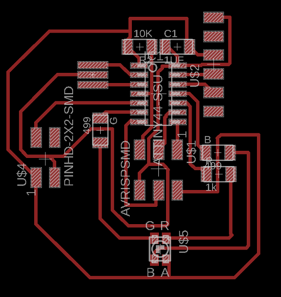
Then I switched to board view. My board has a lot of jumpers because I suffered to connect the traces and I spend more than one day to connect the traces. The width of my traces is 16 mil . Whatever I was very disappointed so I start to think that it's not convenience that people or companies spend days and hours to connect the traces. I did some search about the tips and trick in eagle and I found this The Top 10 PCB Routing Tips for Beginners I found this useful tutorial and it helps me to do it faster.
I remember later that I saw some fab students using jumpers and we had a jumper in FabISP. Then I use a jumper and it's making my life easy. I don't really want to use a lot of jumpers but I found this way faster to connect traces.I followed this useful tutorial on how to add a jumpers.
as usual, I always faced issues and errors. this time showed me an error while I add the fab module file in DRC.
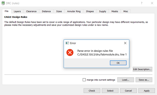
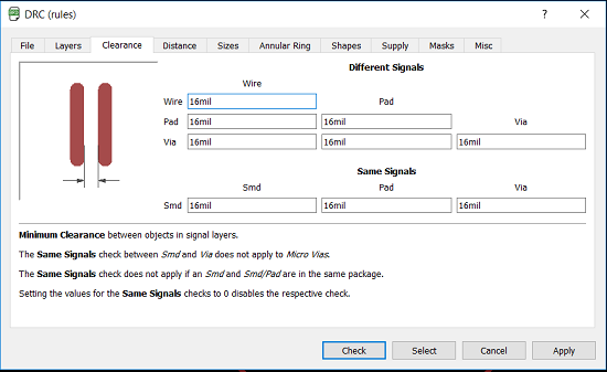
I was stuck so I asked for Francisco Sanchez help. He created for me a new DRC file. I used it and it was really helpful. after I milled the board its came without any trace connected to other.
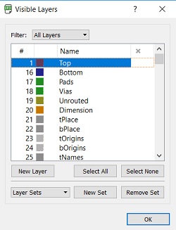
I chose the top layers and I press OK
Then I go to File > Export > Image
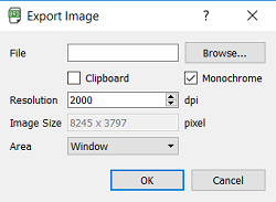
I opened paint and I cropped the and I create the outline file. I did same as I did in week 7. I used SRM-20 to mill the board. I showed all the steps in week 5. I soldered all my component.
I used Arduino IDE for programming. I searched for a tutorial on how I can program my RGB led and I fond this tutorial for Adafruit. I changed the pins and I changed the colors. I select the numbers according to this chart. When I 255,0,255 which is according to the chart should be pink but It is shown as green. I changed the numbers to 0,255,0 which is green according to the chart but it showed pink.
Wendy pointed me to
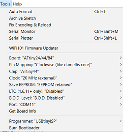
This is my tools settings for connection my board to Arduino IDE
I redesigned the board without any jumpers this is the redesigned board.
As a part of this week assignment, We had to measure the power consumption of an output device. So what I did was connect a power supply. I set the voltage to 5 V then I closed the power supply and connect the VCC and GND on my board.
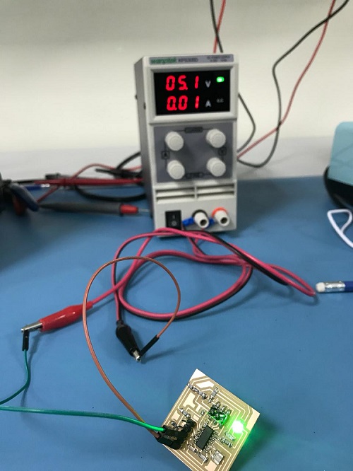
Then I opened the power supply again and I got 5.1V and 0.01A 5.1*0.01 = 0.051 W
File
ProgramPCB
Schematic
Redesigned PCB
Redesigned Schematic