Molding And Casting
What is a Mold ?
A mold is a hollow container used to give shape to molten or hot liquid material when it cools and hardens.
What is a Casting?
An object made by pouring molten metal or other material into a mould.
Credits : FormLabs
Types of Molding
Typical uses for molded plastics include molded furniture, molded household goods, molded cases, and structural materials.There are various types of techniques to make mold on basis of the application.
Types are as givwen below :
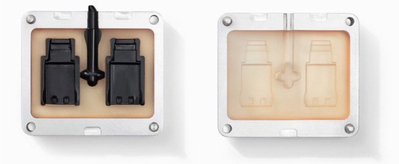
Injection Molding
Injection molding is used for creating high-quality three-dimensional objects, that can be commercially reproduced. The molding process begins by melting plastic in a hopper. Then the plastic is injected into a tightly closed, chilled mold. The plastic quickly takes the shape of the surrounding mold. Once it has completely set, the mold is opened and the plastic object is released. Yogurt pots, butter tubs, toys and bottle caps are made using this process.
Compression Molding
The most labor-intensive type of molding process is compression molding. Therefore, it is only used for large-scale production purposes, and not for mass production. For example, boat hulls and car tires are made using this method. Molten plastic is poured into a mold. Then a second mold is pressed into it. This squeezes the plastic into the desired shape before being left to cool and removed from the mold.
Credits: MechanicalInfo/WordPress
Blow Molding
Blow molding is a process used for making piping and milk bottles. Plastic is heated until molten. Then it is injected into a cold mold. The mold has a tube set within it, which has a particular shape when inflated. So, while the plastic is molten, air is blown into the tube and the plastic is formed around the tubing. It is then left to cool and removed from the mold.
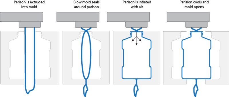
Credits : GeminiGroup
Rotational Molding
Toys, shipping drums, storage tanks and items of consumer furniture are made using rotational molding. Each object is made by coating a mold from the inside. A mold is held in place between two mechanical arms. Then, the arms rotate the mold constantly at the same level, while molten plastic is placed inside. As it turns, the plastic coats the inside of the mold to create a new hollow, plastic object.
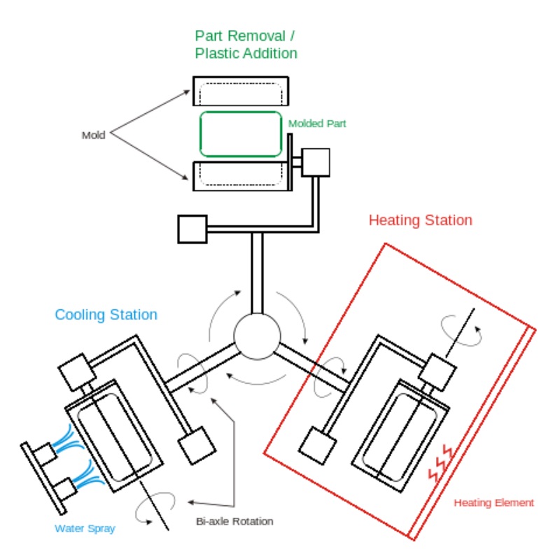
Credits: WikiPedia/RotationalMoulding
Making 3D Mould (-ve)
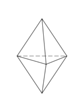
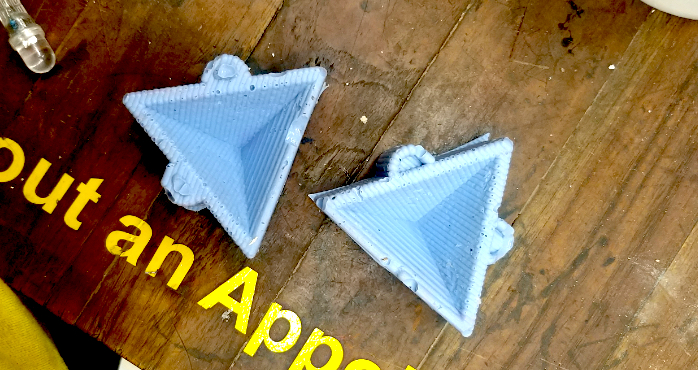
I started with defining what I want with my mould. I wanted to make a module with two pyramids stack on eachother as given below.
I wanted to make these types of single-double modules.
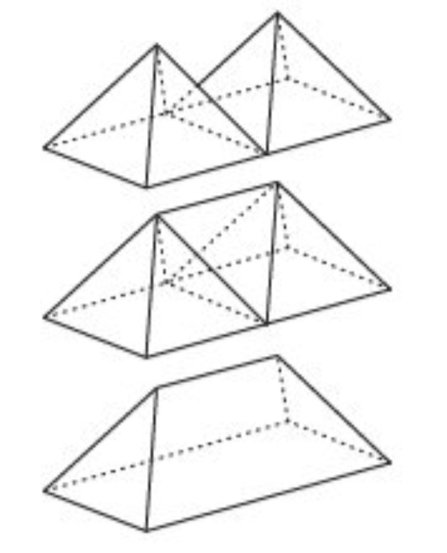
Using above I could make any 3D structure.
Using Fusion 360
I designed my mould to machine it using Fusion 360. The machine wax block that I used was 150x90x35 mm. Thus design has to be smaller to machine it.
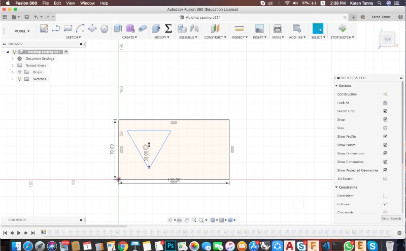
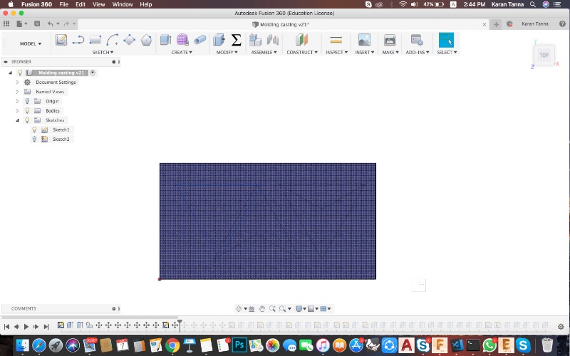
Step 1 : I opened up and made basic sketch of design with following dimensions.
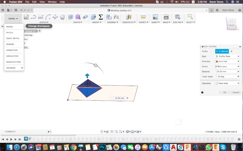
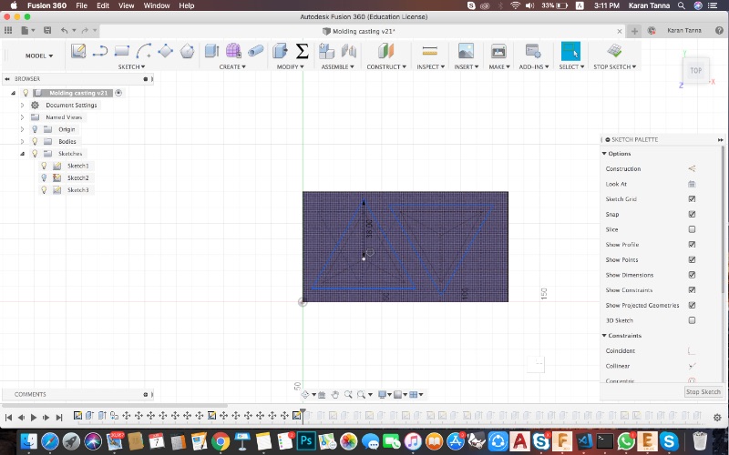
Step 2 : Then I extruded triangular surface to 25 mm using taper angle 30 degress (See right side panel).
Step 3 : Then I extruded my block to height 35 mm after hiding other sketches and bodies.
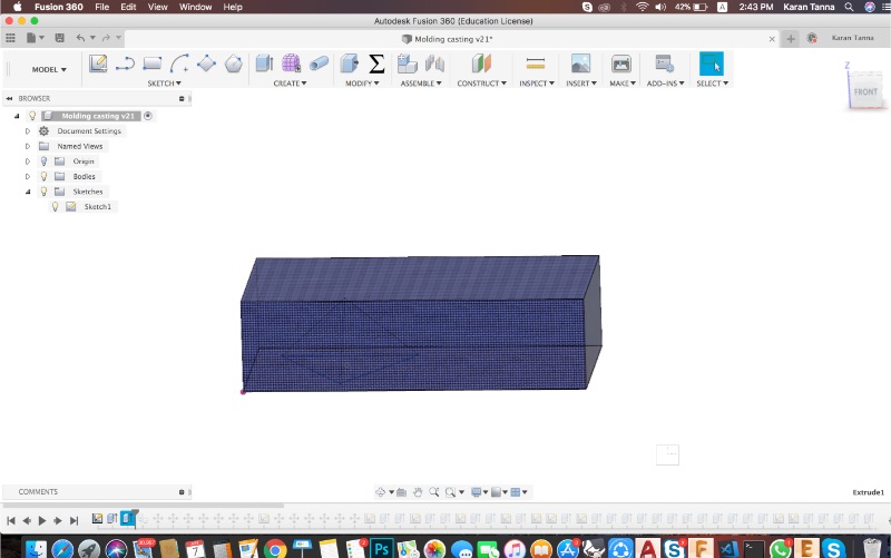
Step 4 : Then I made visible the block.
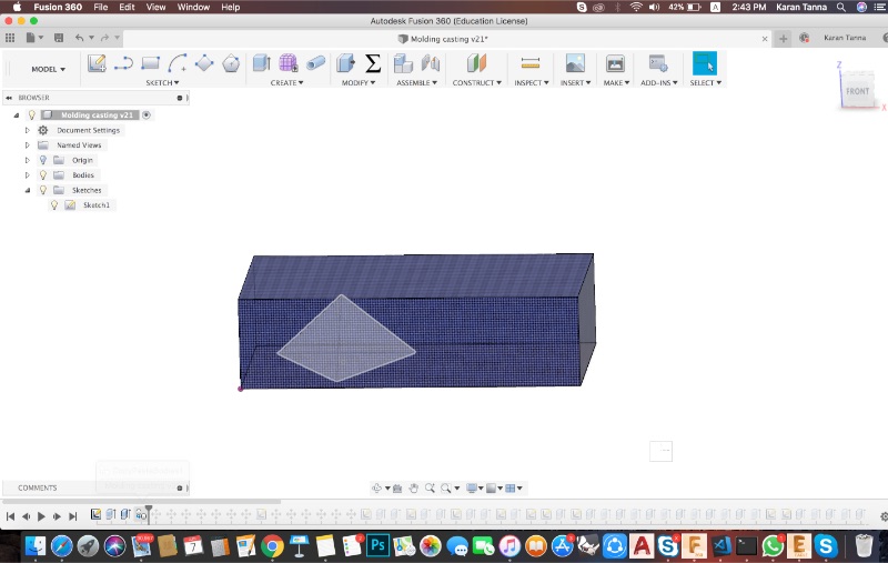
Step 5 : I copied the block .

Step 6 : I rotated it in opposite direction to optimise the space.
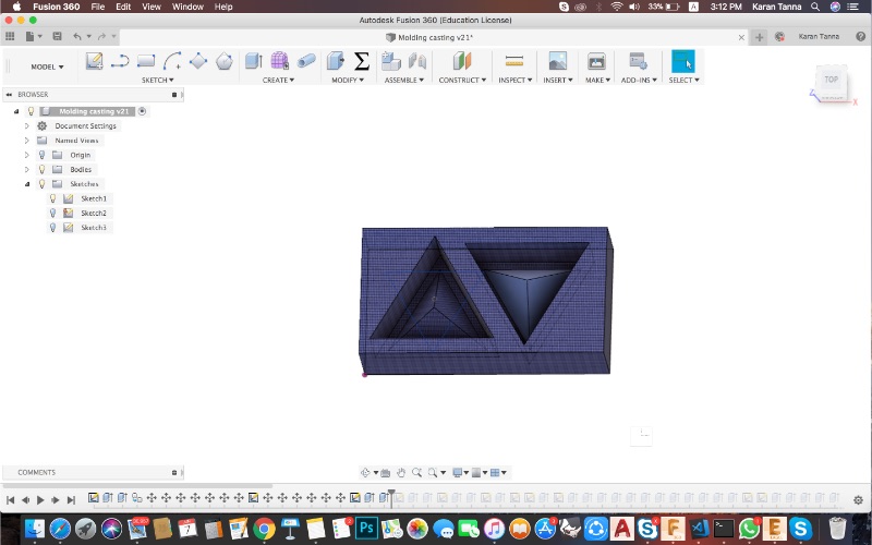
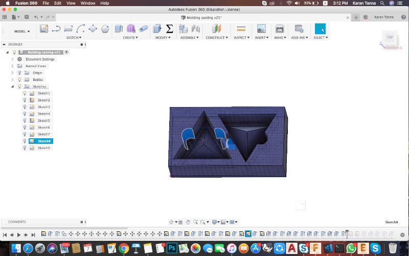
Step 7 : Then I rearranged it and made bigger triangle on top suraface.
Step 8 : Then I extruded down the bigger triangle with 'cut' process.
Step 9 : Then using mid-point of sides I made semi-circles of 15 mm diameteron both triangles.
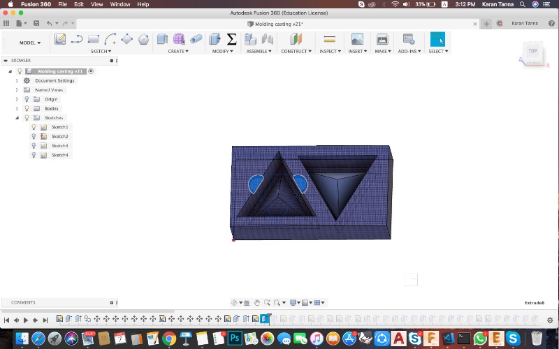
Step 10 : Extruded down using cut process to the same level of base of traingle. Then made inner semi-circle with clearance more than tool diameter. (In this case diameter was 8 mm.)
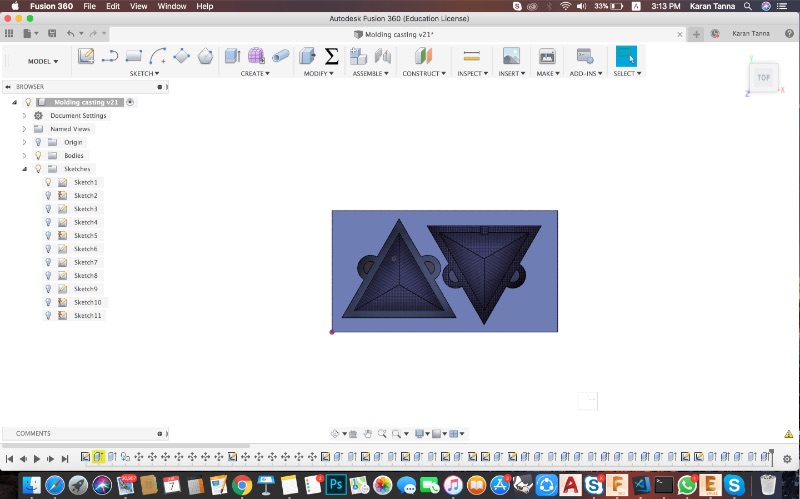
Step 11 : Extruded Inner semi circleit down to -5mm level on first triangle and to level +5mm on second one.
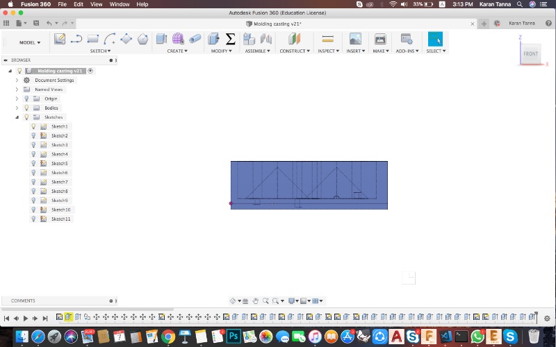
Step 12 : From the side it will look like below. (Note keep some clearance (2.5mm minimum) from tip of pyramid to have thickness on positive mold.)
Note : I have connected a pipe (semicircular) in design to insert material.(injection molding)
Step 13 : The final design will look like below.
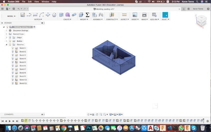
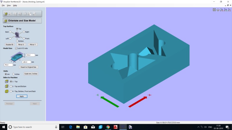
Step 14 : Then I exported it to .STL to further generate toolpath.
3D Design
Machining using ShopBot CNC
I used pathworks 3D software to generate toolpath for ShopBot CNC Machine.
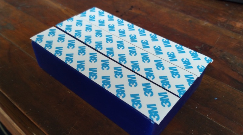
First of all put double side tape on the back of wax block and mount on the CNC machine bed. Do check the level (degree) using compass and level app on phone or level meter.
Using PathWorks
Step 1 : Import the .stl file into pathworks software.
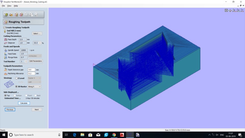
Step 2 : Then follow the navigation bar steps. In step 4/7 you'll get roughing tool path. I used following parameters for Roughing Toolpath.
Step 3 : Then select tool paramets for rounghing. Parameters I used are as below.
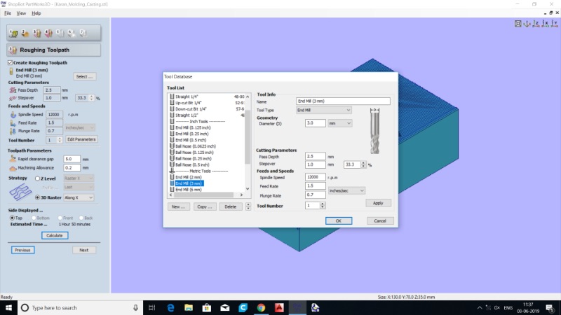
Tool 1 : Parameter Table
Step 4 : For Finishing tool path I used following parameters.
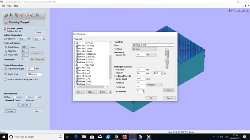
Tool 2 : Parameter Table
Step 5 : Then further preview and save the tool paths. (Roughing And Finishing- Save it in two differnt files.)
Step 6 : Open ShopBot App (Here ShopBot 3). Insert the milling bit and then set X,Y,Z origins.
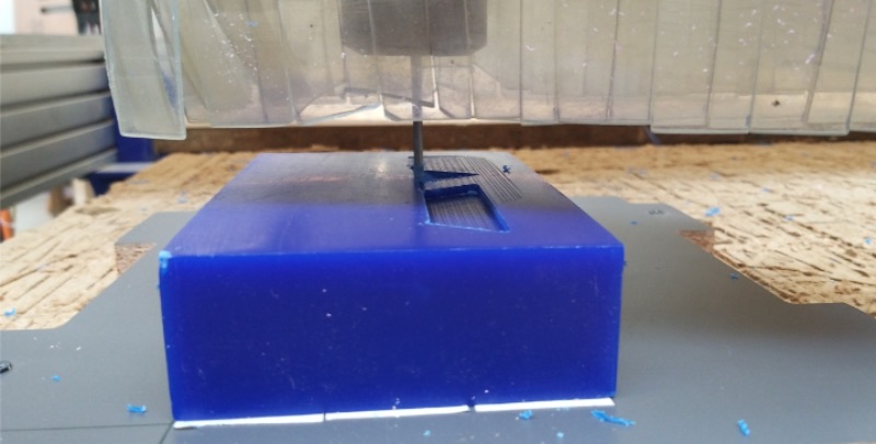
Step 7 : First run roughing tool path and then finishing tool path using 'cut part'.
After that remove it using spatula.
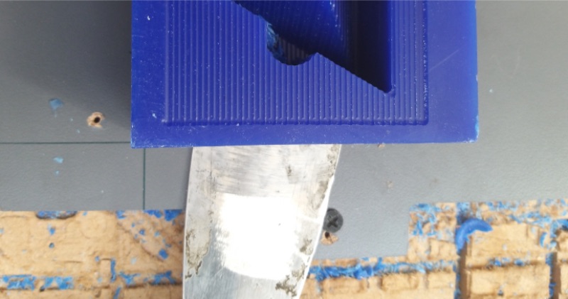
It would look like below.
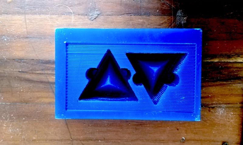
You can find all the files at the end of page.
The mould still had lines over it. It would also affect mould and the cast also. It could have been further improved by slight parameter changes.
1. You can reduce the step over. Flatter the slope, the smaller step over you are forced to use in order to minimize your cusp height.
2. For wax lower RPM works better ie.2000-4000 as it is soft material.
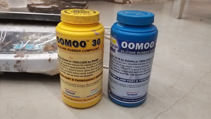
Making Mold using OOMOO-30.
Read data sheet before using it and use safety equipments while using it.
Find product info using link below.
Measure the amount of mix that you want by water. (make more as density of omomoo is more.)
Put vaseline or greese on the machined wax so that mold gets out easil
Add part A in a cup. (Add half the amount by weight in the cup.)
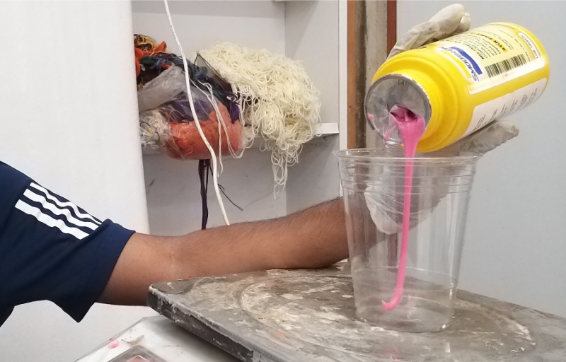
Similarly add part B in the cup. (Add half the amount by weight in the cup.)
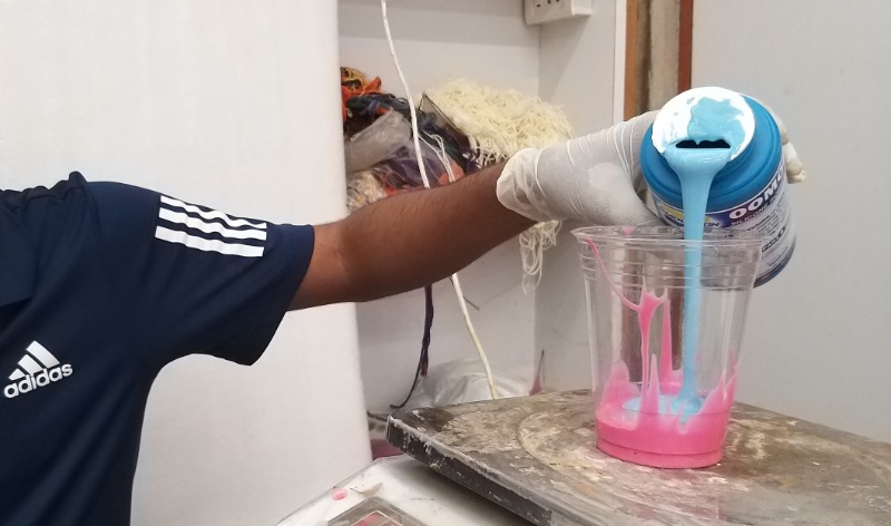
Then mix it firmly. for around 20-25 seconds as mentioned.
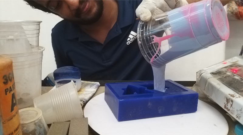
Quickly pour it into mould and keep tapping wax block to make it levelled and fix the air gaps.
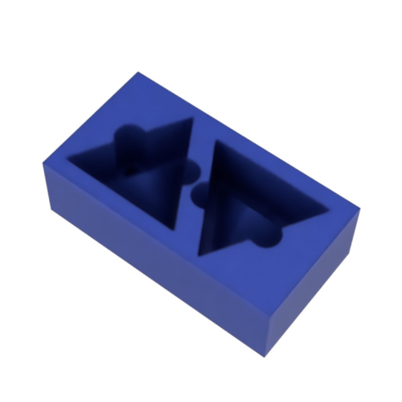
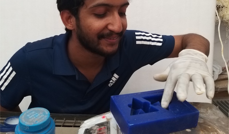
Leave it to set for 6 hours. And remove the mold.
It would look like below when removed.
Casting
I used Aditya Silicon's Silicone RTV Rubber0- 4040- Translucent Material. It has proportion of Part A: Part B :: 10 : 1. It has hardness Shore A 40. I wanted to put LED inside each module.
Find product info using link below.
This process is similar to above.
Measure the total amount you need by volume to cast. You can test it by wanter and calculating density.
This particular product uses 10:1 ratio thus divide it into 11 parts. (Zero the measure after putting glass.)
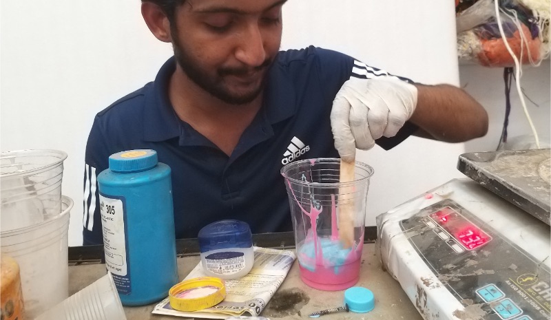
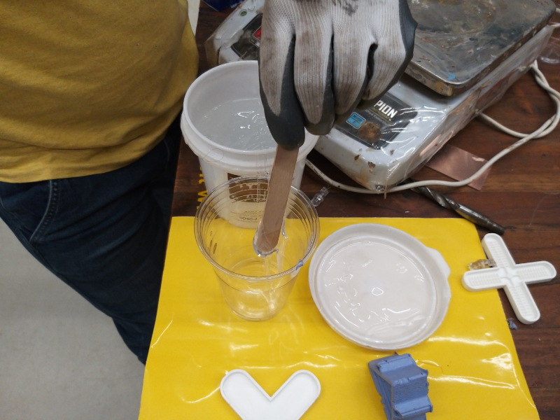
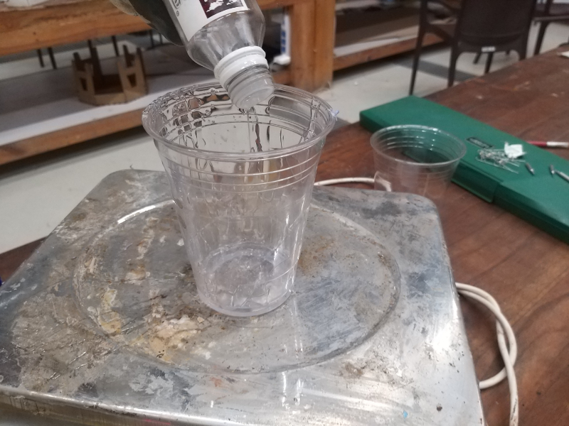
Step 1 : Measure 10 part Part A. Pour it into the mixing glass.
Step 2 : Again after zeroing the measure. Measure 1 part Part B. Pour it into the mixing glass.
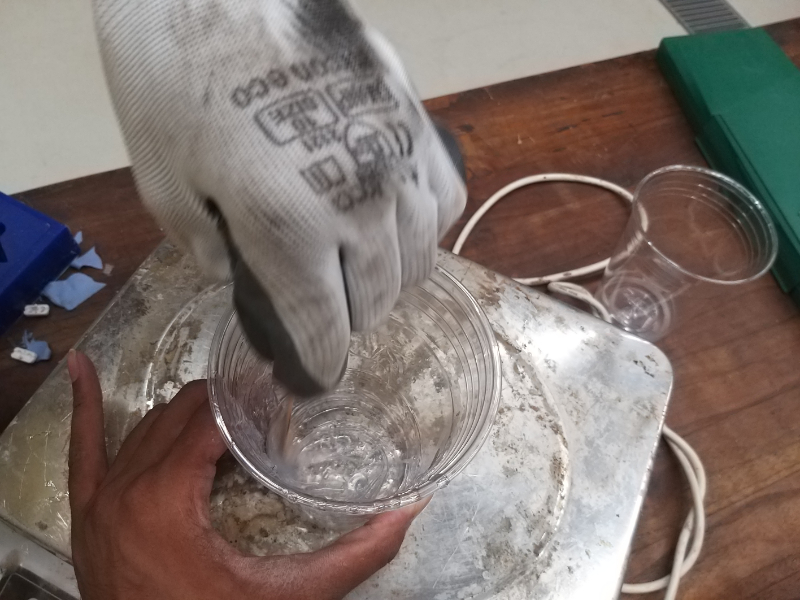
Step 3 : Mix it firmly for around 30s. (Then I put LED in it with terminals outside, for later use. As it is transparent I wanted to use it and make it attractive,
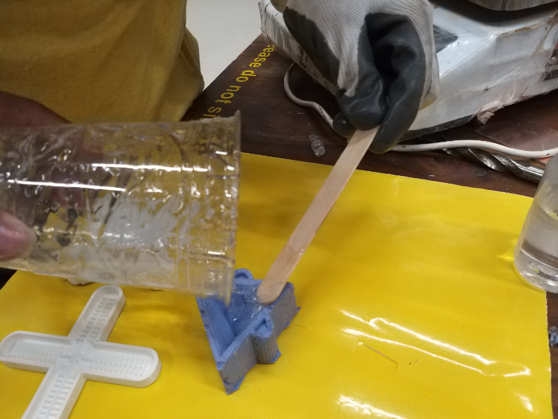
Step 4 : Pour mix into the mould. Tap the mould so that liquid settles and then wait for 6-12 hours. Remove it after it cures. It is soft thus it will be easy to remove.
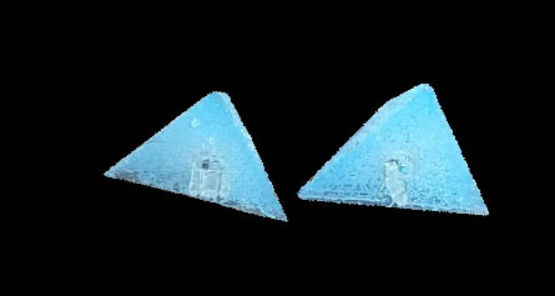
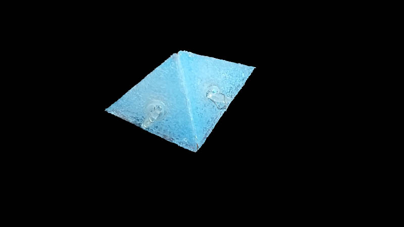
Final Product
Contribution to Group Work
This week we tested several materials. We made cast using various materials.
This week I contributed into documenting the process of documentation and making content and comparing.
What Did I learn ?
This week I learn about three step molding and casting process. Also I learned how to do 3D milling (CNC).
I learned the Injection molding process and how to design files for that.
I tried various kinds of material and techniques to learn about various material properties.