Week 14 : Networking and Communication
Networking and Communications. This week is about how to make two boards talk to each other.
Networking and Communications. This week is about how to make two boards talk to each other.
This week I planned to finish I2C communication.
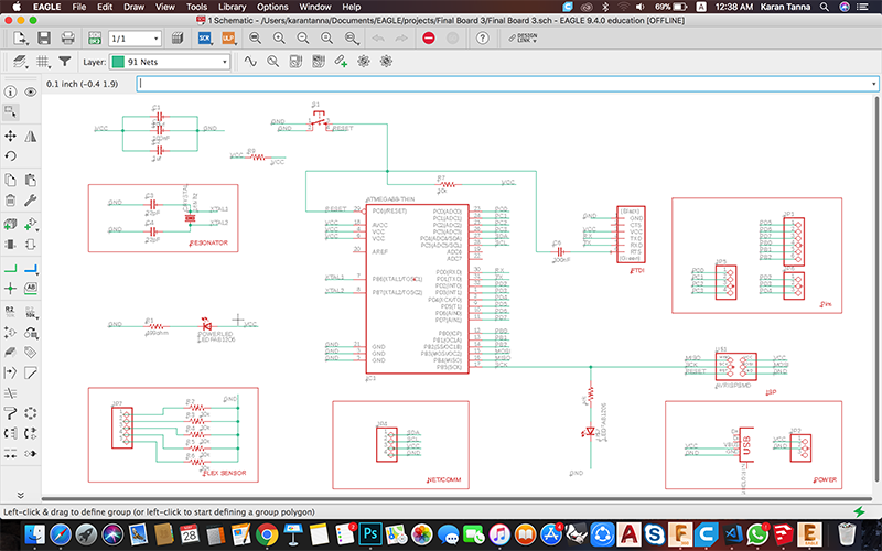
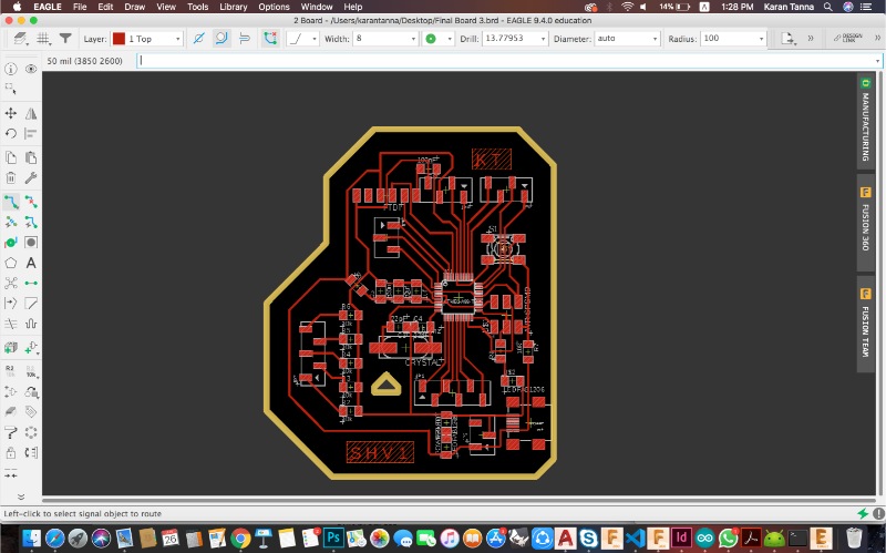
Schematic & Board Diagram of 328P -Slave Board
I2C combines the best features of SPI and UARTs. With I2C, you can connect multiple slaves to a single master (like SPI) and you can have multiple masters controlling single, or multiple slaves. This is really useful when you want to have more than one microcontroller logging data to a single memory card or displaying text to a single LCD.
SDA (Serial Data) – The line for the master and slave to send and receive data.
SCL (Serial Clock) – The line that carries the clock signal.
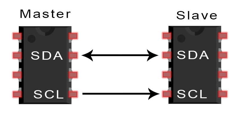
I2C is a serial communication protocol, so data is transferred bit by bit along a single wire (the SDA line).
I2C is synchronous, so the output of bits is synchronized to the sampling of bits by a clock signal shared between the master and the slave. The clock signal is always controlled by the master.
With I2C, data is transferred in messages. Messages are broken up into frames of data. Each message has an address frame that contains the binary address of the slave, and one or more data frames that contain the data being transmitted. The message also includes start and stop conditions, read/write bits, and ACK/NACK bits between each data frame.
To learn in detail follow the link below.
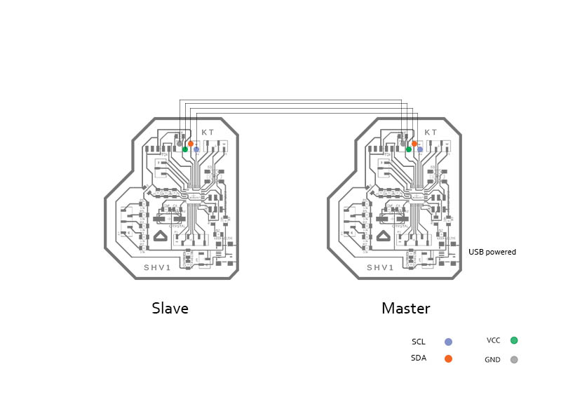
I used two 328 P boards which I made previously for simple I2C comunication with Single master - Single slave model.
Here I tried to initiate communication between two boards. I have one single Slave and Single Master board. I have addressed the board (8). Also Master sends data and slaves recieve data. When it recieve (1) it turns led on slave (pin 13) High. When recieves (0) it turns it off.
//Master i2c

		#include <Wire.h> // Add angular bracket before and after Wire.h.
		                //This includes wire library of arduino.
		void setup() {
		  Serial.begin(9600);
		  Wire.begin();
		}

		void loop()
		{

			Wire.beginTransmission(8); //slave number 8
			Wire.write(1);
			Serial.println("1");
			Wire.endTransmission();
			delay(1000);
			Wire.beginTransmission(8); //slave number 8
			Wire.write(0);
			Serial.println("0");
			Wire.endTransmission();
			delay(1000);


		  }
		//i2c slave
		#include <Wire.h> // Add angular bracket before and after Wire.h. This includes wire library of arduino.
		int d1=0;
		void setup() {
		  pinMode(13,OUTPUT);
		  Serial.begin(9600);
		  Wire.begin(8);     //change address
		  Wire.onReceive(recieveEvent);
		}
		void loop() {
		  if (d1 == 1)
			{
			  digitalWrite(13, HIGH);
			}
			 else
			{
			  digitalWrite(13, LOW);
			}

		   delay(200);
		}
		void recieveEvent(int howMany)
		{
		  while (Wire.available())
		  {
			d1 = Wire.read();
		  }
		}
Above codes were for single slave - single master communication. Then from the above codes I edited it to work with Single master - Multi Slaves. In this case 2 slaves.
Fun Fact : For a 8 bit message communication. 328P board master can handle upto 125 slaves. Thats huge right ?
Below are the codes for single master multi slave.
#include <Wire.h> // Add angular bracket before and after Wire.h.
				//This includes wire library of arduino.
void setup() {
  Serial.begin(9600);
  Wire.begin();
}

void loop()
{

  Wire.beginTransmission(8); //slave number 8
  Wire.write(1);
  Serial.println("1");
  Wire.endTransmission();
  delay(500);
  Wire.beginTransmission(9); //slave number 9
  Wire.write(0);
  Serial.println("0");
  Wire.endTransmission();
  delay(500);


  }
			//i2c slave
			#include <Wire.h> // Add angular bracket before and after Wire.h. This includes wire library of arduino.
			int d1=0;
			void setup() {
			  pinMode(13,OUTPUT);
			  Serial.begin(9600);
			  Wire.begin(8);     //change address
			  Wire.onReceive(recieveEvent);
			}
			void loop() {
			  if (d1 == 1)
			  {
				digitalWrite(13, HIGH);
			  }
			   else
			  {
				digitalWrite(13, LOW);
			  }

			   delay(500);
			}
			void recieveEvent(int howMany)
			{
			  while (Wire.available())
			  {
			  d1 = Wire.read();
			  }
			}
			//i2c slave
			#include <Wire.h> // Add angular bracket before and after Wire.h. This includes wire library of arduino.
			int d1=0;
			void setup() {
			  pinMode(13,OUTPUT);
			  Serial.begin(9600);
			  Wire.begin(9);     //change address
			  Wire.onReceive(recieveEvent);
			}
			void loop() {
			  if (d1 == 1)
			  {
				digitalWrite(13, HIGH);
			  }
			   else
			  {
				digitalWrite(13, LOW);
			  }

			   delay(500);
			}
			void recieveEvent(int howMany)
			{
			  while (Wire.available())
			  {
			  d1 = Wire.read();
			  }
			}
***Identical boards are slaves and the other board is master in above video.
If you see above boards it has only one I2C pin. Now I need two I2C pins for Single Master -Multi (Dual) Slave. Thus I wanted to make connectors which make life easier. (Also if you want to connect 10 slaves, you can't mill new board each time.
As a solution I took female throughhole component for this and copper tape (you can use copper wire). In this case I needed common SCL and common SDA. I had 3 pins for each I cut 3 pins and then joined bottom part with copper tape as shown below. You can use as many as you want.
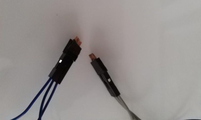
On one side common SCL and other side common SDA pins.
I struggled a lot. I had no electronic background. Thus it was very big challange. Also I had to find-out ways of soldering with one hand. Thus after week 7, started making iteration. I had lot of failurs.
I tried making many boards and Improved upon PCB design and soldering.
Image below shows image of all.
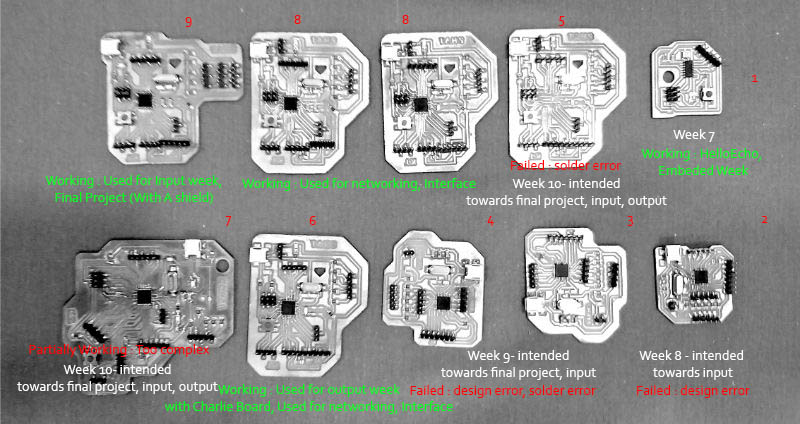
Sucessful Boards : Top Row
Failures include : (Bottom Row) : (1) Placement error, Soldering error. (2) Soldering error. (3-4) Design Error. (5) Design & Soldering error.
This week we tried to address boards and tried to network them and make them communicate with eachother.
You can visit group page by clicking the link at the end of page.
I learned about I2C bus communication. I learned about how to make boards communicate.
Also I learned from problem I faced that. It is always good idea to keep things modular. ie. Initially I did single master - single slave communication. But then when I had to connect more boards, it was not capable. Evan if I had made two I2C port it won't be sufficient. Thus this led me to find a solution. And I found simple and effective solution for that.