8. Computer controlled machining
After I learned that our task was to “Make something big,” my thoughts immediately went to making a nightstand for myself. My current nightstand is circular and is therefore quite inconvenient due to its shape. I wanted to create a nightstand (that isn’t circular) that would have several different storage areas.
Fusion
I really struggled with designing this piece, especially because it had so many interlocking parts. At first, I made it with zero clearance, meaning that there was no built in extra space between tabs and slots. Then, I realized that that probably wouldn’t work very well, so I restarted and tried to design clearance into it. I was really struggling with designing the clearance in when Mr. Rudolph said that zero clearance actually works. Even if it doesn’t fit at first, you can sand it down or just hammer it in very forcefully. So, I went back to designing with zero clearance. I restarted again (I didn’t use my original zero clearance because my parameters were off), this time again using zero clearance. It took a lot of work to make sure all the tabs and slots lined up perfectly, but I did it. For the sake of brevity, I am only documenting the final process of creating the nightstand with zero clearance.
First, I determined that I wanted to design a nightstand with several storage areas, with some off to the side so I can access them easily while I’m lying in bed. I drew out how the compartments would be:
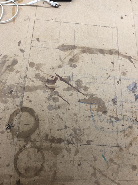
I wanted to physically draw it out so that I could see exactly how large each compartment would be. I also found my exact measurements, for example, for how large the base would be, etc.
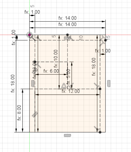
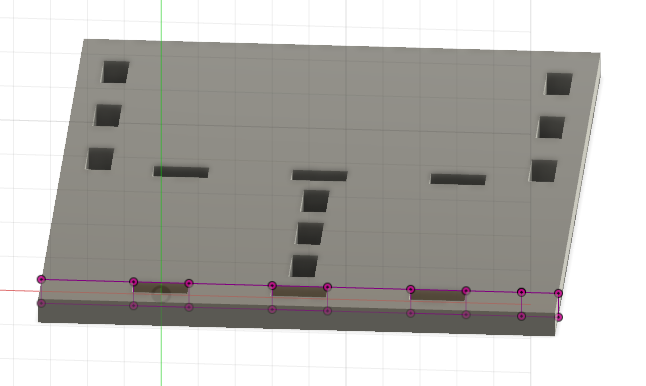
I then created the base in Fusion, based off of the sketch I did by hand. I determined that I wanted my tabs to be 1.5 inches long, and t long (the parameter for thickness). I made a user parameter for the length of the tab (1.5 inches), which I called tab. Then, I extruded t inches.
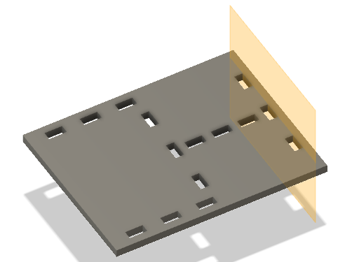
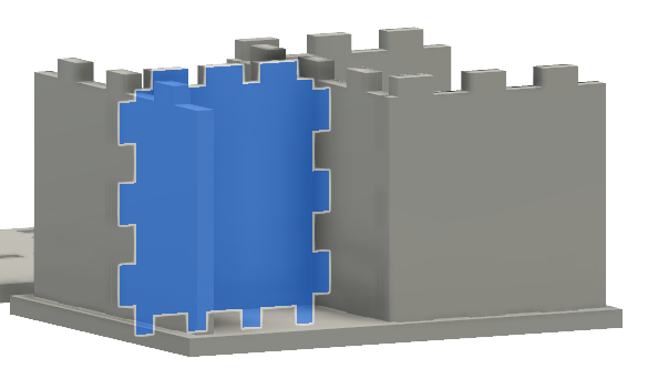
Using the faces created by the extrude, I created an offset plane and projected the shapes of the tabs onto the new plane. Using this projection and the mirror tool, I was able to create the back vertical piece. I made it (and all of the other vertical pieces) 9 inches tall. Again, I extruded it t inches.
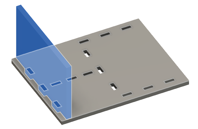
Using this method of projecting and extruding, I was able to create the vertical pieces somewhat quickly.
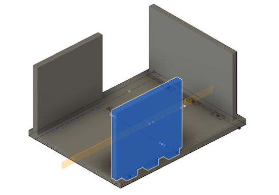
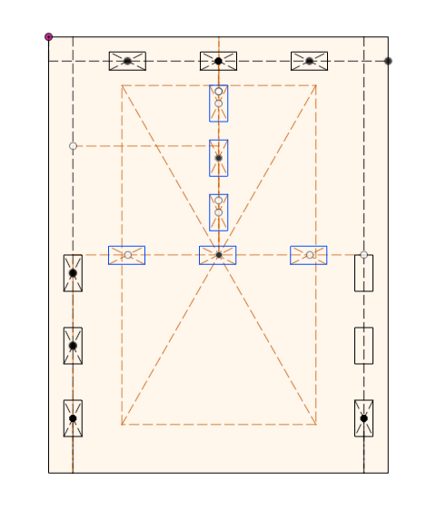
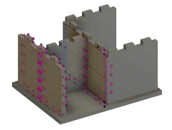
The difficulty came in the interlocking of the other pieces. The actual method was not exceedingly difficult. Similar to what I just explained, I projected and extruded, whether that was a cut extrude or an extrude creating a protrusion of the material. An example of the various projects I had, resulting in a final shape:
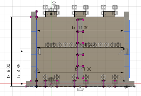
By the end, I had a lot of projects.
Instead of reinventing the wheel when it came to the top of the table, I simply copy and pasted the original base sketch and extruded it up, not including the slots designed for where the legs would fit in.
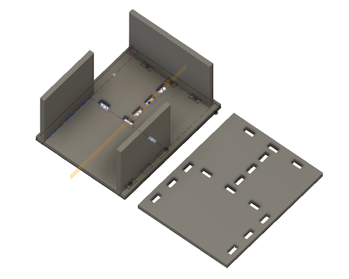
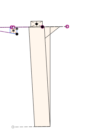
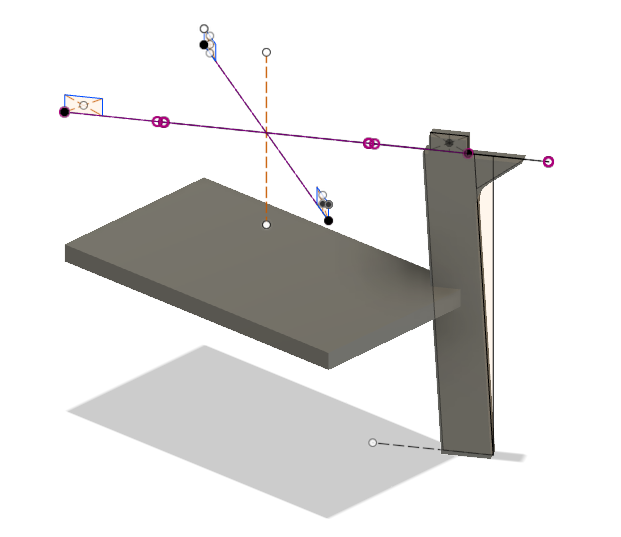
Once I finished the shelving, I moved on to the legs. I hid the other bodies and, again, used an offset plane from the base body. I designed the leg somewhat arbitrarily, aside from the fact that I knew I wanted the legs 13 inches tall, 2 inches wide, and at an angle. Later, when I discussed the legs with Dr. Fagan, he was concerned that the legs would splay out when I assembled it. After consulting Mr. Rudolph, I determined that the inner support shelf that I had created would help prevent the legs from separating. He also suggested creating a shoulder that would be toward the outside of the table, which I implemented in my design.
Aspire
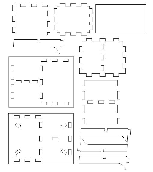
I had never used Aspire before this; previously, I had just used the toolpath editor that was built into Fusion. Once I had the svg files of each piece, I compiled them all into one Corel document. I placed them strategically, using the least material possible. I then saved this Corel file as a different svg file.
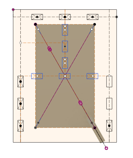
I put this svg into Aspire, and since I had defined the page size in Corel (width of 96in and height of 48in), I did not have to change the sheet size. I did, however, change the thickness of the material to .75in. As I did during the group project, I made sure that all the vectors were closed. Then, I went into Fillet and selected Dog Bone. I selected all of the places where I wanted the fillet:
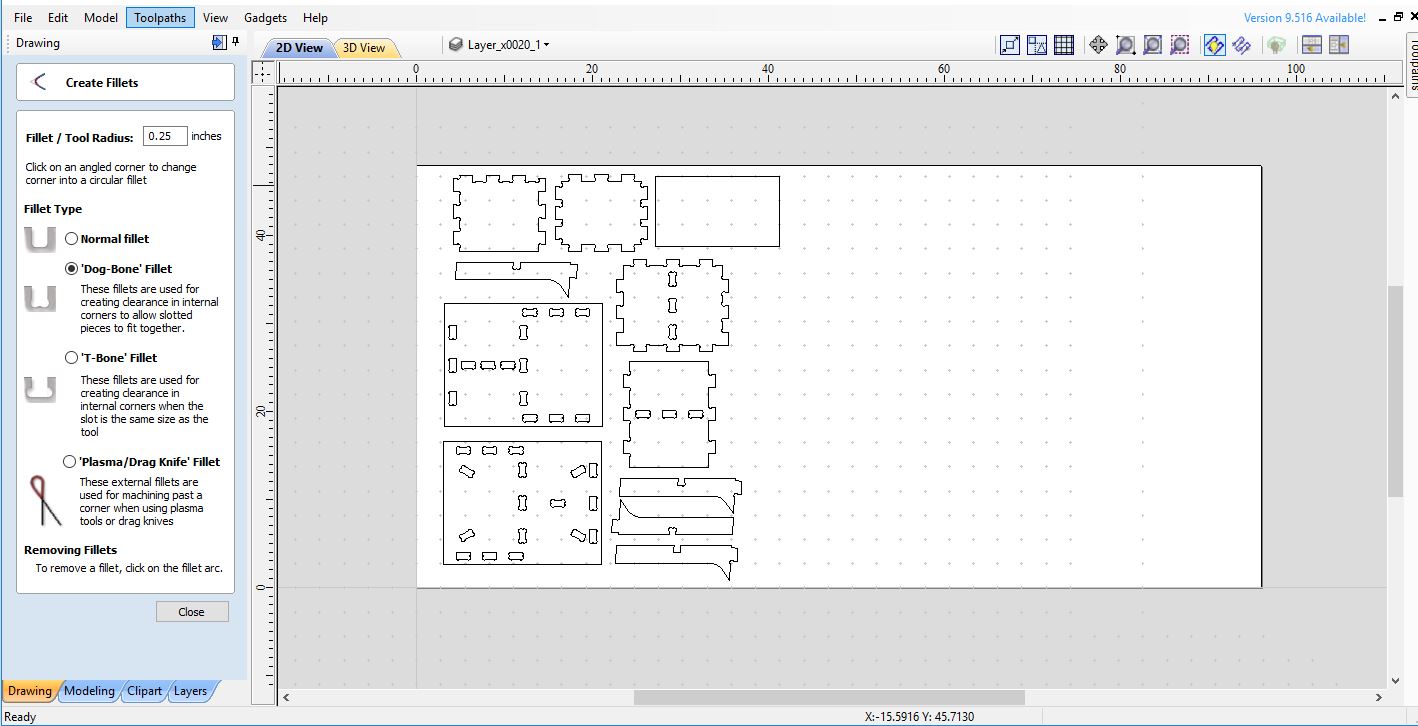
As shown in the photo, I indicated that the Radius of the bit was .25, which was incorrect. My diameter was 0.25, causing the dog bones to be excessively large. Aside from aesthetic obviousness, this did not cause me any problems. Next time, I will make sure I input the radius and not the diameter.
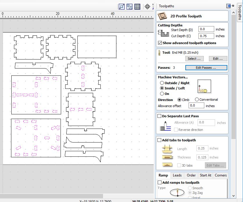
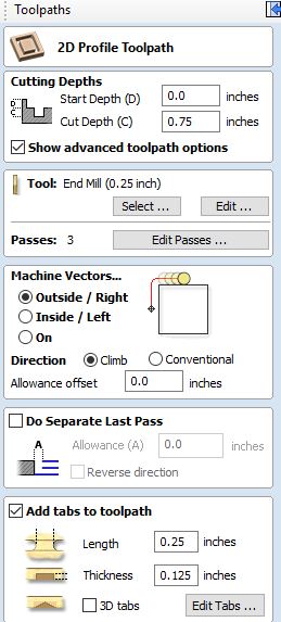
Then, I went to the Toolpath section on the left side of the window and selected 2D Profile Toolpath. I wanted to design two separate toolpaths, since one toolpath will be cut outside and one will be cut inside. The photo shows my settings for both of my toolpaths and I will draw attention to settings I changed:
-
I made sure the cut depth was the same thickness as the piece of wood I was using.
-
The default number of passes was 6. I changed this to 3 to speed up the process. I was informed by Mr. Rudolph that, generally, it is safe to do one pass as deep as its diameter. In this case, 3 passes on a 0.75in thick material would be 0.25in being cut per pass. Since the bit I used was 0.25in, this was safe to perform.
-
I changed the setting to Inside/Left or Outside/Right according to which toolpath I was working on (slots or outlines, respectively)
-
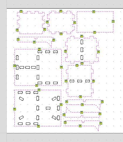
I added tabs to my design by clicking Add tabs to toolpath. Then, I clicked where I wanted to place my tabs, usually 4 on each piece, with one on each side. A little yelow box with a T on it would appear, indicating that the tab would be there.
After changing all of these settings, I named them in such a way that I could distinguish between the two toolpaths and pressed Calculate. To save each toolpath as an sbp file (a file that the ShopBot can use), I pressed on the SD card icon in the Toolpath window. I saved each toolpath (inside and outside) separately by making one visible at a time.
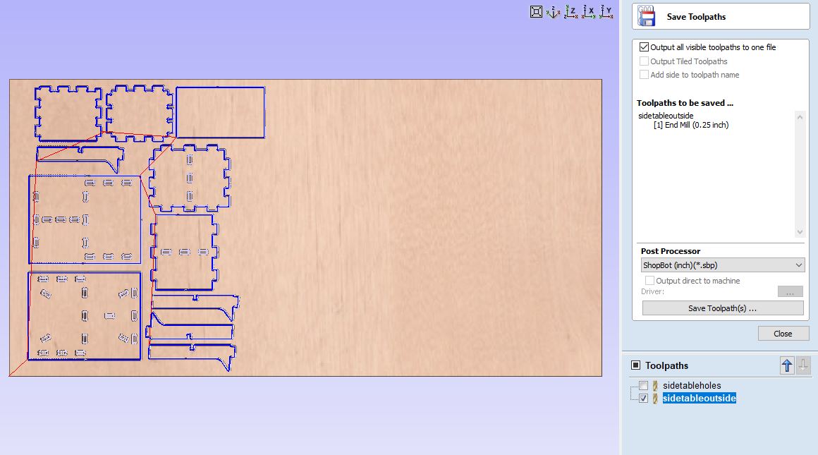
These were the files that I loaded to the ShopBot later in the process.
Download my nightstand (Aspire file)
Download my toolpath .sbp files
ShopBot
Setup
Since I had watched the others go before me and fully participated in the test cuts for the group project, I thought I would have all the commands down. However, when I got up to the machine, it was very different. For example, I knew how to jog the machine, but it was very different actually being the one telling the machine how far to move on the X and Y axis. I personally had to be the one estimating distances as to how far I wanted it to go, and that was a new experience.
Throughout this whole process, I used this tutorial which was made by Tom Dubick, a Fab Academy grad.
Once I got to the ShopBot, I immediately moved it to a place in the table that wasn’t destroyed using the J command so that I could zero the Z axis. I did not have to change the bit, since it already had the bit I wanted (0.25 in). To zero the Z axis, I:
1) Used the J2 command to move the bit to a place in the table that was not destroyed, moving only the X and Y axes.
2) Put the Z axis plate underneath the bit.
3) Plugged in the Z axis plate, with the right orientation.
4) Used the C2 command to start the zeroing of the Z axis.
5) Made sure I followed instructions as the popup prompted.
6) Pressed enter and watched the bit as it descended onto the Z axis plate, adjusting as necessary to make sure that the bit would hit somewhere in the middle of the plate.
7) Waited until a popup told me that the zeroing process was complete.
8) Unplugged the Z axis plate.
Then, I put my piece of wood on and screwed it down. I placed the screws so that it would not get in the way of the cuts.
Instead of using the normal (0,0) as the origin, I wanted to use (1,0). I jogged the ShopBot over to this location and then used the command (Z2) to set that location as the new origin.
Cutting
Aircutting is a useful tool that enables the user to see that their cut is in the right place and that the toolpath seems correct. It is where the Shopbot follows the given toolpath raised in the air instead of while cutting the material. To perform an aircut, I:
1) Opened my file by going to File and then Part File Load.
2) Selected what I wanted to cut first (the sbp file with the toolpath for the slots).
3) Changed the offset to 3D Offset.
4) Pressed enter.
5) Followed the instructions of the popup, pressing the green start button to start the spindle.
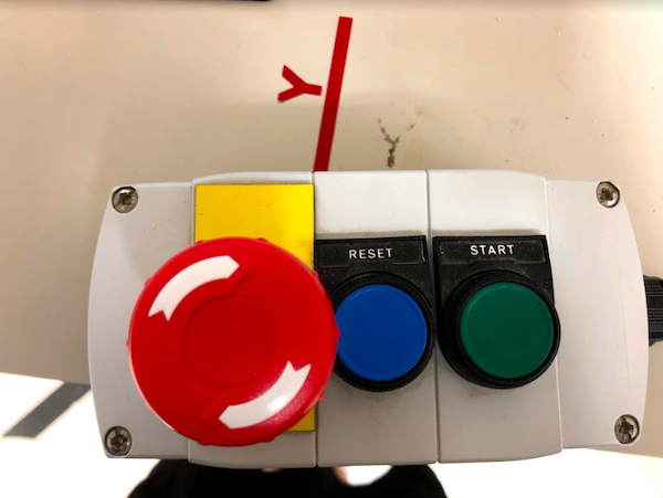 .
.
6) Pressed OK on the popup, which started the bit onto the toolpath.
Once I was satisfied with the aircut, I pressed the space bar or the STOP button on the computer. When the popup appeared, I pressed Quit.
To perform the actual cut, I repeated steps 1 and 2 above. I left the offset at No Offset, pressed enter, started the spindle, and started the toolpath. Since I had changed my passes just to 3, the cutting did not take very long. When it finished, I repeated the same process with the toolpath of the outside cuts.
Cutting of both inside and outside toolpaths (2x):
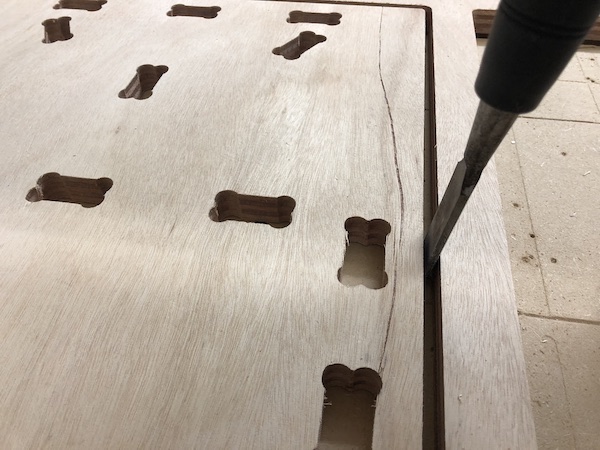
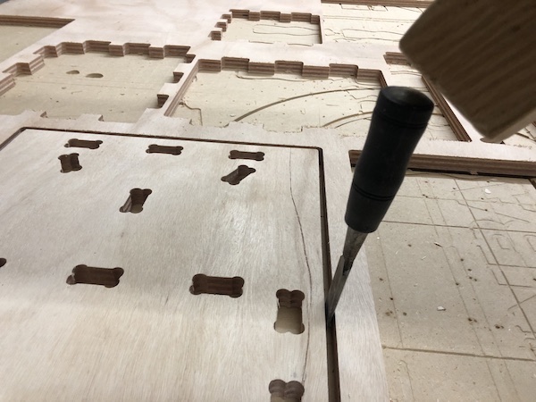
Chiseling
In order to remove the cut pieces from the Shopbot (since I had created tabs when I made my toolpath), I had to use a chisel. I used the flat end of the chisel and put that against the actual piece and used a mallet to cut off the tab. I repeated this process with all the tabs I created, which was about 3-4 per piece.
Assembly
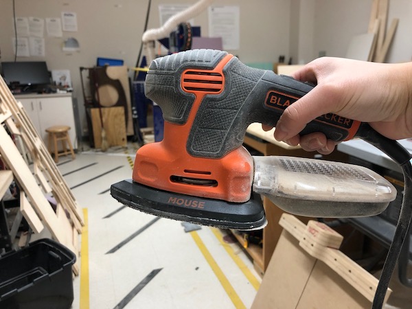
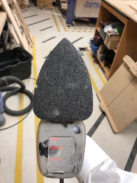
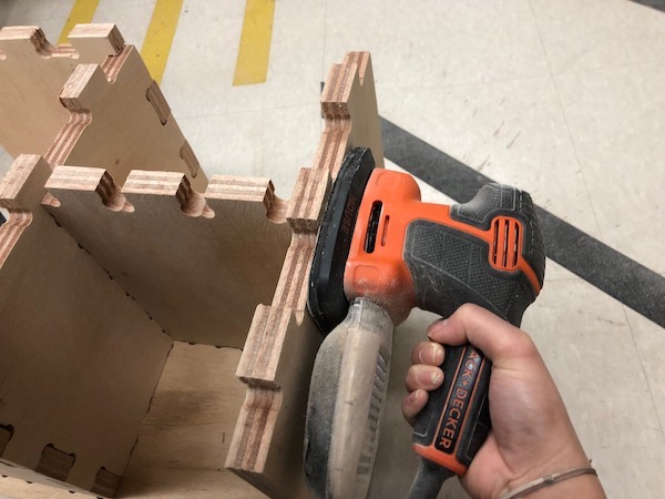
When I took the pieces off of the ShopBot, they were quite rough and needed sanding, especially on the edges. I used a power sander to accomplish this task.
When I originally measured my board, I noticed that its thickness was inconsistent (ranging from 0.71 to 0.76). This property of the board that I was using made itself apparent while I assembled. Generally, the tabs fit into the slots quite well, but there were a few where the tab was much too wide for the slot or where the tab was almost too small for the slot.
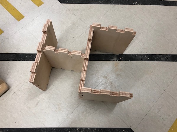
First, I assembled the vertical parts:
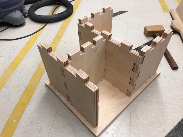
Then, I put the base on:
Putting the top on proved to be more difficult than putting the base on, which surprised me. I had to sand some tabs down so that they would all fit into the slots.
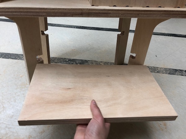
When I tried to assemble the legs and the support board, I realized that the support board was far too long for the slots I designed in the legs. I think I just designed it incorrectly when I made it in Fusion. I still don’t really know how I designed it wrong in Fusion, but I just rolled with it. In future iterations of a nightstand, I could design a simpler support that would fit orthogonally into my leg pieces. In other words, I would not put my legs at 45 degree angles; rather, I’d design it so that everything uses 90 degree angles. This would make adding the support much simpler.
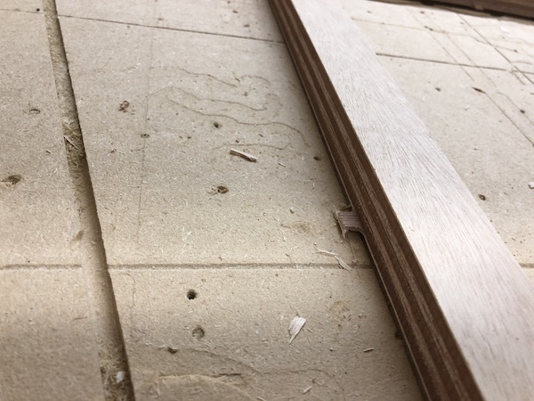
At first, I just assembled the nightstand without the support and planned to just forgo it. However, I realized that I had come too far in this process for it to have a somewhat glaring defect. I decided to try to cut the support board with the table saw so that the support board would fit. I eyeballed how long the board should be, indicated that line, and cut it with the tablesaw.
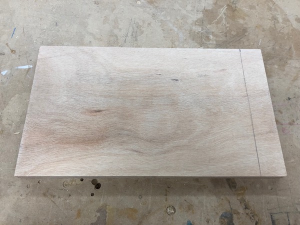
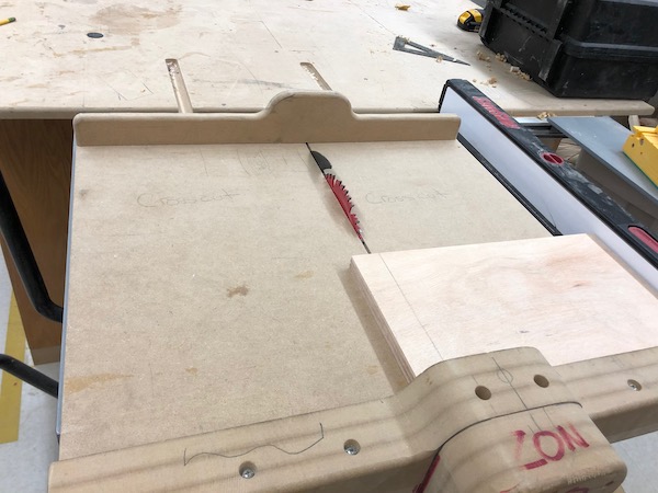
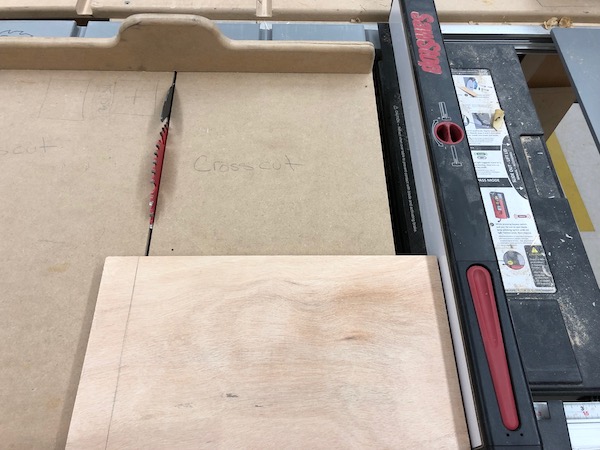
Thankfully, my makeshift support board fit perfectly.
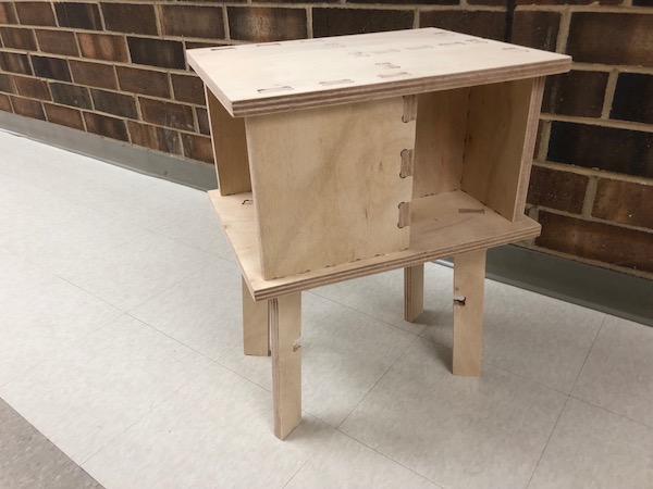
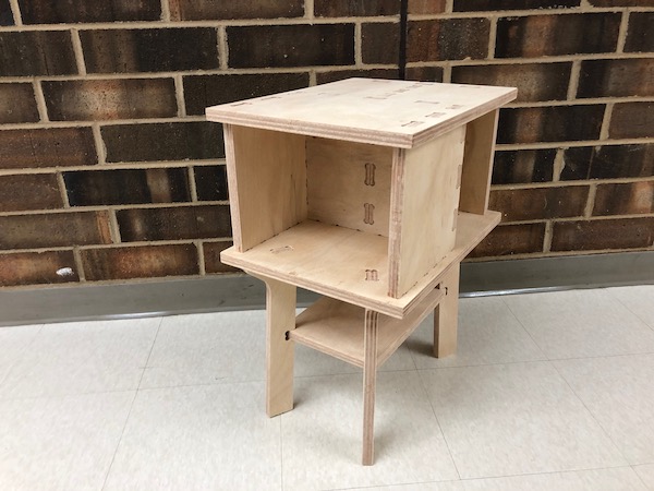
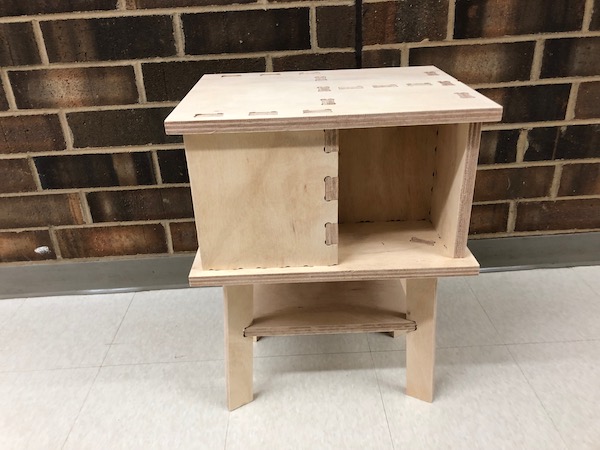
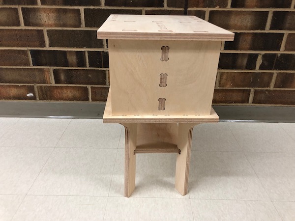
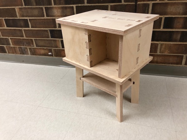
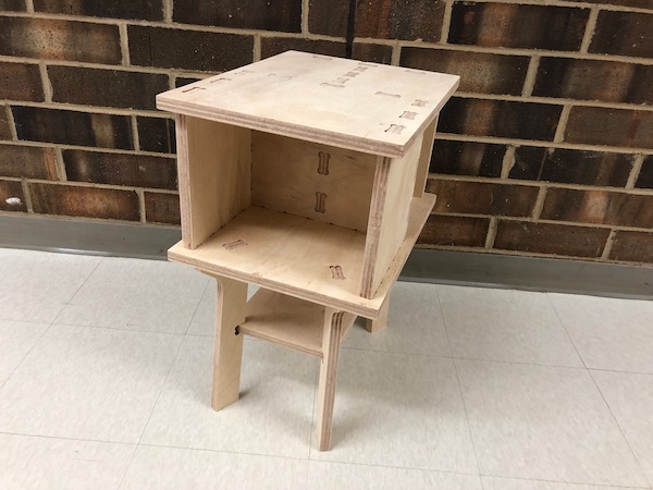
Final nightstand:
Group Project
For the group project, I designed a test for clearance, creating a slot. I also created a piece with just a line going through it to test the real width of the bit. I did so by following the same process I detailed above for the personal aspect of this week.
Download the toolpath sbp files
We used the Z plate and zeroed the Z axis:
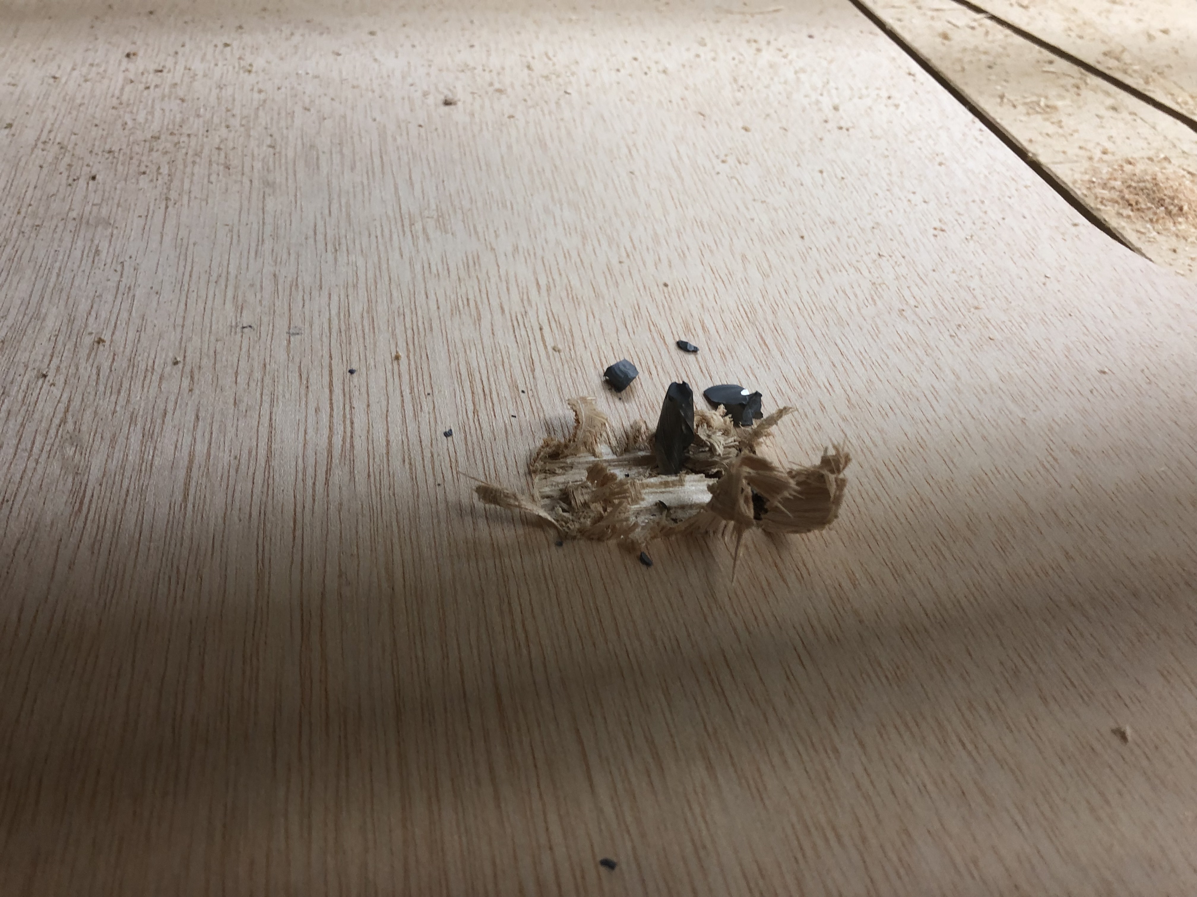
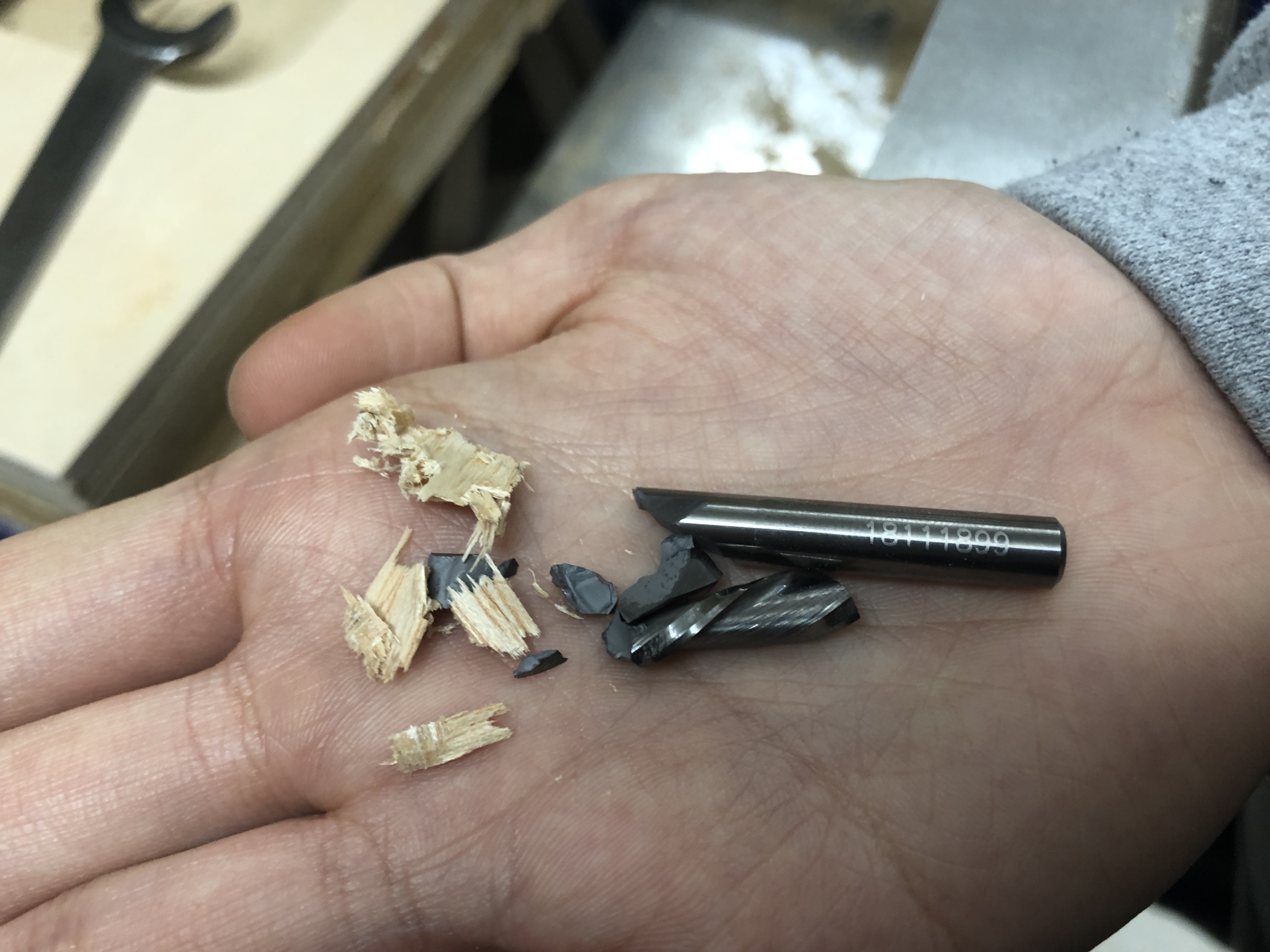
When we went to run the cut, we started the cut without starting the spindle. We broke the bit because we forgot to start the spindle. No one noticed until the spindle hit the table and made a really loud noise as it broke. We did our group project at the beginning of the week (meaning none of us had used the ShopBot a lot prior to doing the group project), so we were really prone to mistakes to begin with. We now know that, before running a cut, you must press the green start button on the control box to start the spindle.
Here’s the inside toolpath and outside toolpath cutting:
The two pieces (the tab and the slot) fit really nicely together!
Summary
I really loved this week; it was really cool to be able to make something so clearly and definitively my own. I also got a really cool nightstand out of this week, and I’m already using it in my room as I intended when I designed it. I learned a lot of new things this week. Though I knew how to design stuff in CAD, I never knew how to make a toolpath. I did kinda know how to use the ShopBot before this week, but now I know it really really well, especially since I milled my parts during Spring Break. I didn’t have Katie, Will, or Kai to ask stuff quickly, so I had to figure out a bunch of things for myself. I could’ve asked Mr. Dubick, but I didn’t want to keep bothering him. I know all of the commands for the ShopBot really well (even though I can now easily look back at my documentation above if I ever can’t remember a command), and I just feel confident with the ShopBot/its setup steps.