add an output device to a microcontroller board you've designed, and program it to do something
measure the power consumption of an output device
This weeks assignment was to make a circuit that can control something i.e. output device. To combine this weekly assigment with my final project, the aim of this week is to make boad and connect RGB strips with it, and program it with different effects of lights.So fo this week assignment I decided to make Satshakit and took reference fom Daniel Ingrassia.
After redrawing so much controller boards in past weeks I planned in this week to make my own design, for this I want to make a board which is not only use in this week but kind of general purpose board for me.
I started with designing the board! .Satshakit is a 100% Arduino IDE and libraries compatible, fabbable and open source board, and also an improved version of Fabkit. I used ATmega328p .The ATmega328 is a single-chip microcontroller created by Atmel in the megaAVR family (later Microchip Technology acquired Atmel in 2016). It has a modified Harvard architecture 8-bit RISC processor core.Wikipedia
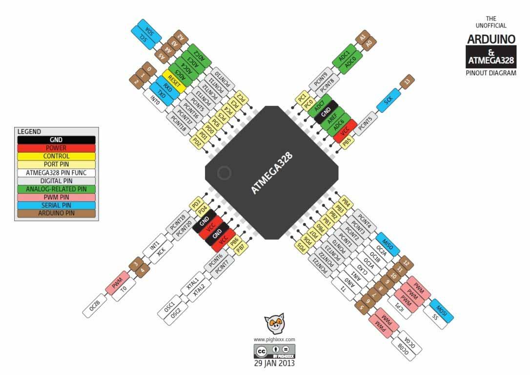
ATmega328
For PCB designing I worked on Eagle 7.5 that I have been using since from Week4. First I made a schematic of board:
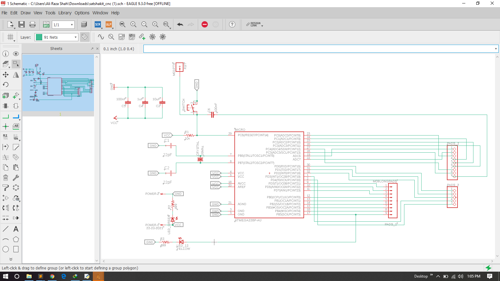
Schematic
After schematic I have generate PCB board and route it as we did in previous weeks .
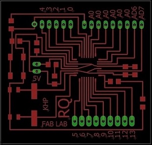
PCB Board
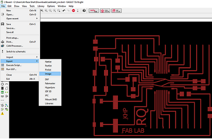
Export as Image
In the appearing window, I increase the resolution to 2000 dpi, click on monochrome, and click Ok.
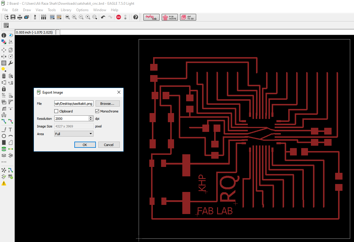
Normal Seting
To edit the .png image, I Used Paint. I open my image in paint, and using the rectangular select tool, I select the image leaving some space from all the sides. After I press File and Copy the selected area. To continue working with the selected picture, I click again on File, and Create from the Clipboard
More detailed procedures can be found in my previous documentation Electronics Design week!
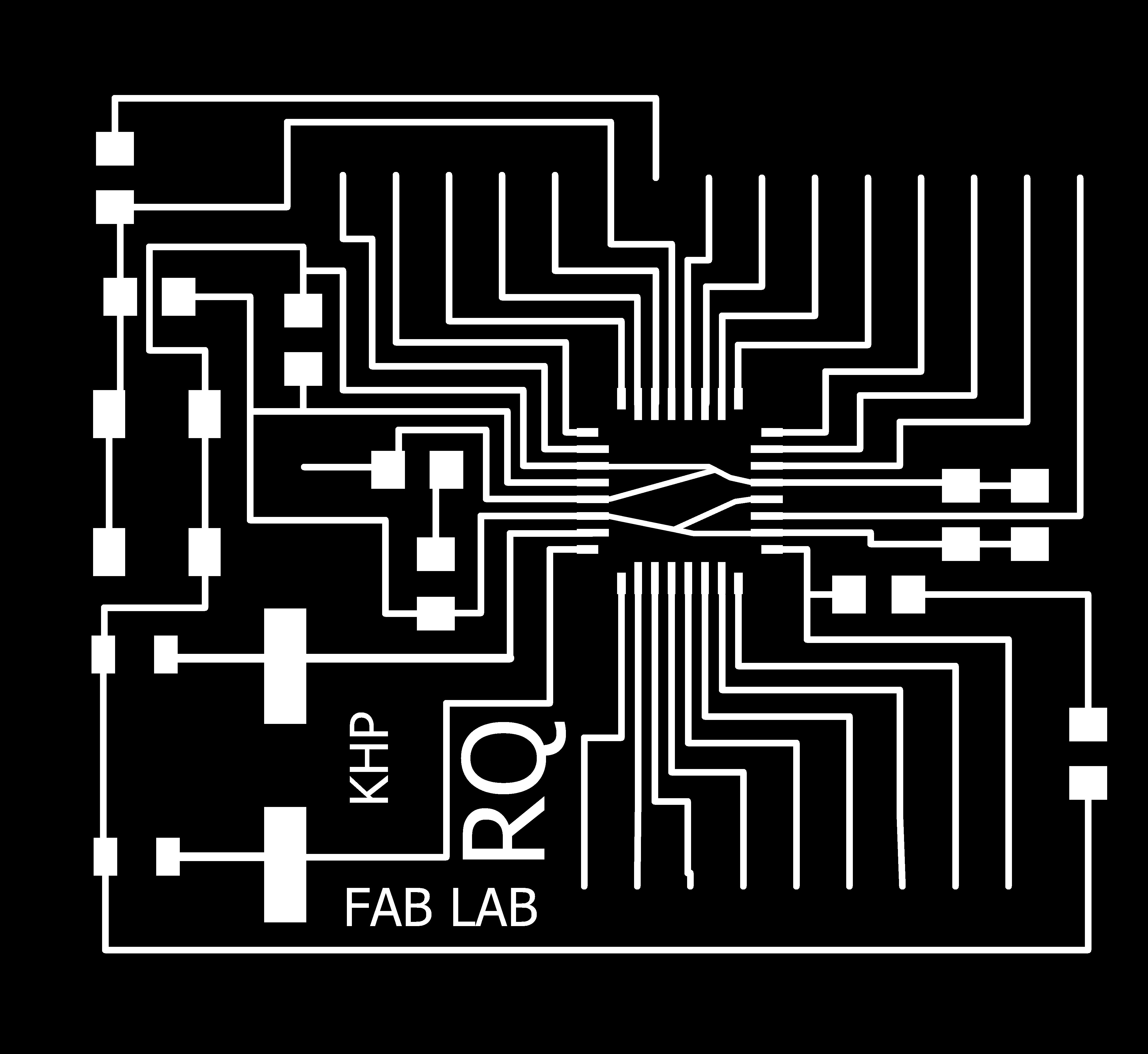
Trace

Outline
after making traces and outline of a pcb I used fabmodules to generate RML files of both traces and outline, all important settings are mentioned for detailed fabmodules settings visit Electronics Production Week

Components
Above list of components files i have generated from Eagle
.rml files are given to Roland SRM-20 for milling, 1/32 drill bit is used for cutting outlines and 1/64 bit drill is used to make a trace on a board and here is the result
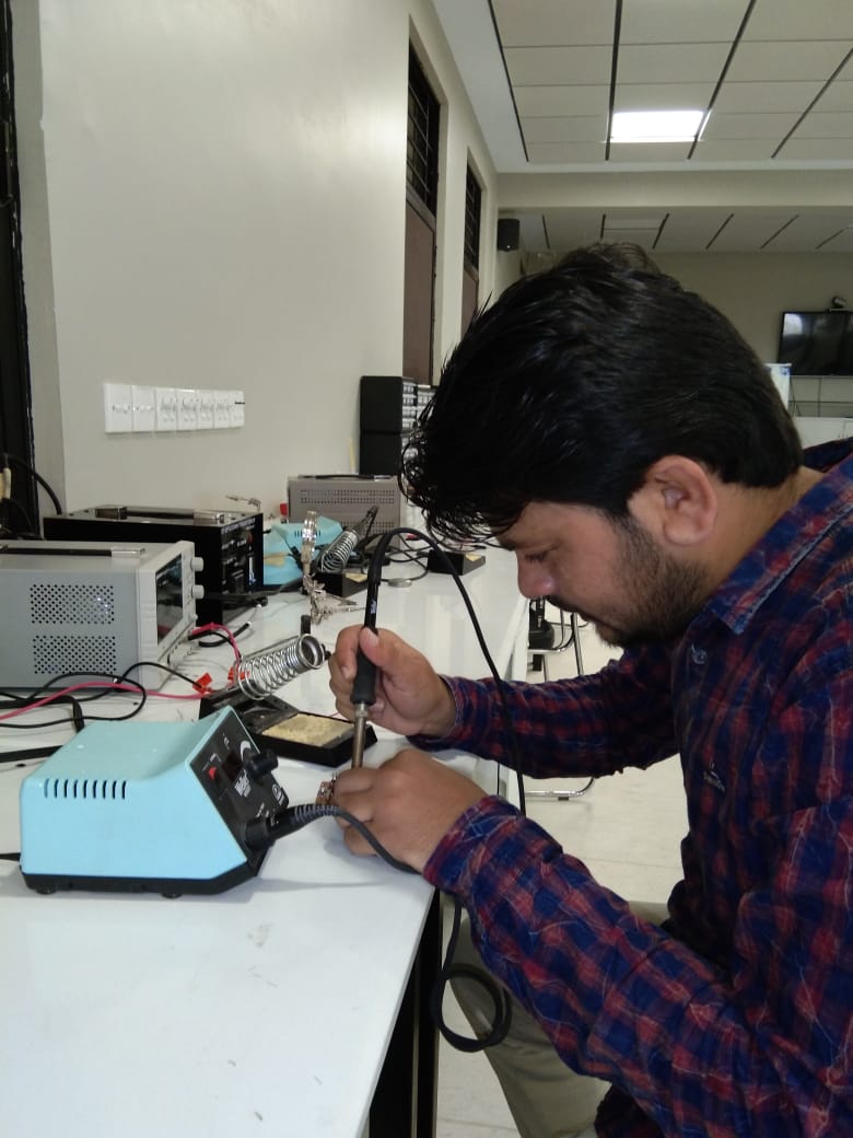
Soldering
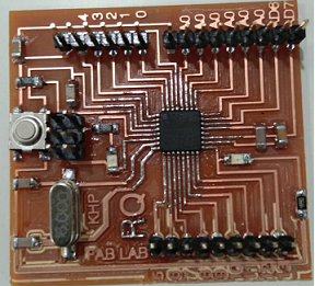
PCB
I am using Arduino IDE for programming my board. Before programming the board first it is required to burn bootloader in it. For setting up Arduino IDE to work with FabISP I mentioned in detail in Embedded Programming Week. I connect the arduino board to the USB. Under Tools select the right board, select Arduino as ISP USBtinyISP, double check the parameters, and press the Burn Bootloader button.:
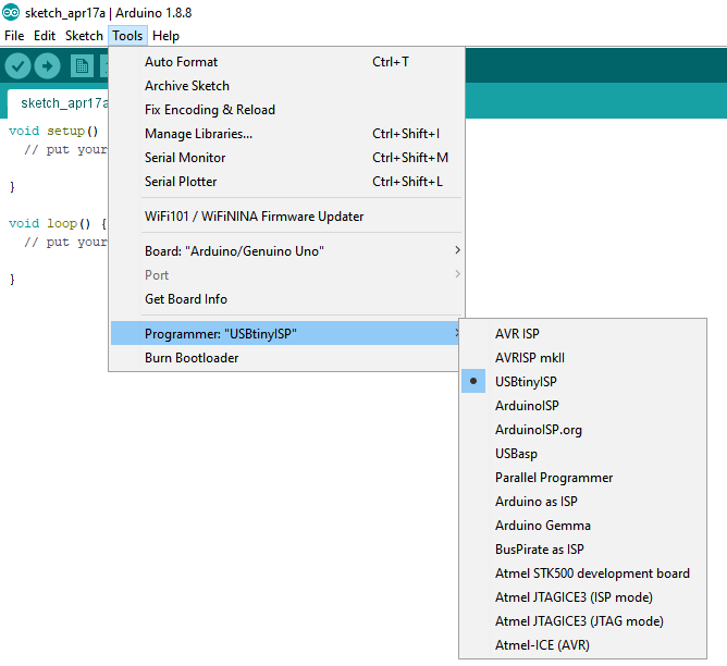
Programmer
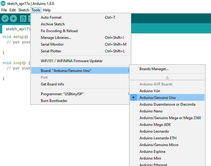
Selecting Board
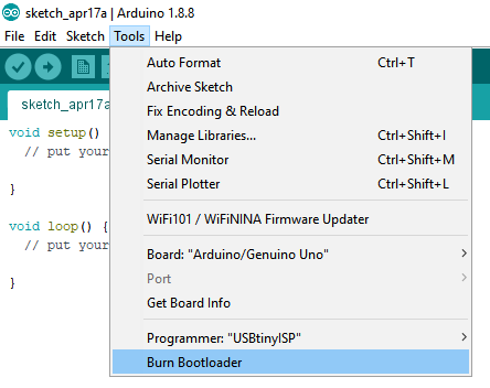
Burn Bootloader
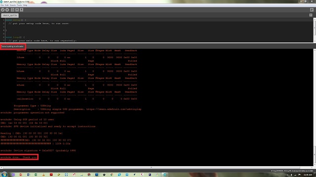
Done Burn Bootloader
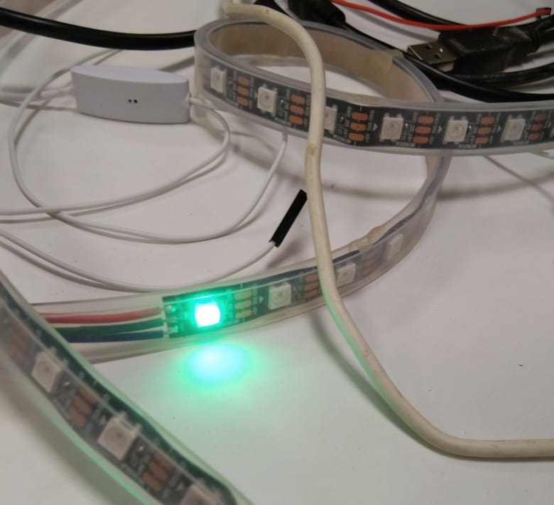
After successfully upload and burn bootloader , now It is time to connect RGB strip WS2812B with board and program it to run differnet color effects
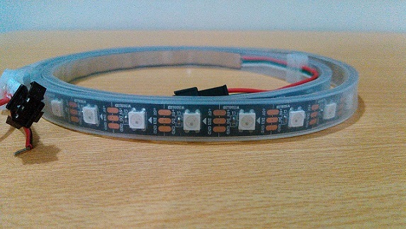
WS2812B RGB strip
Connect RBB strip address pin with Pin-6 of 328p board and connect supply pins VCC and Gnd with external source. I used five volatge adopter for external source
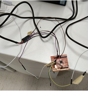
Connection
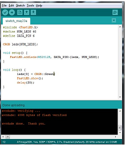
For RGB Led code I go to my local Instrcutor 2018 Student Noor Ahmed Pirwani webpage where he mention fastled library for RGB . I Used fastled Library for differnt patterns ,effects and upload it in my 328p board
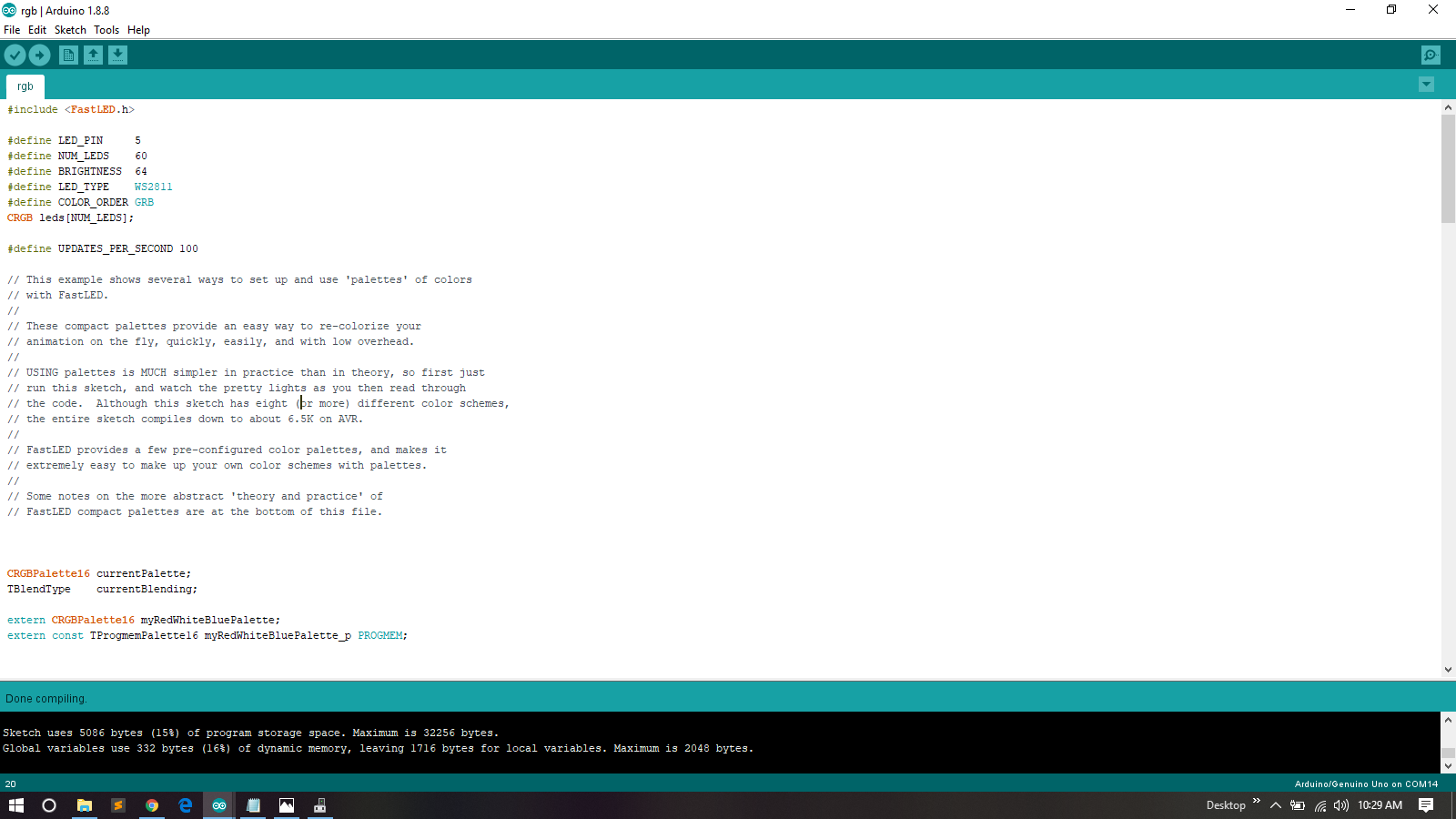
Program
In this week group assignment we have to measure power consumptions of an output device.I Have used Led Strip as output device So I measured power consumptions over a individul Led in strip.
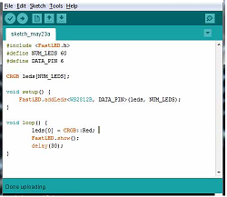
Program For One Led
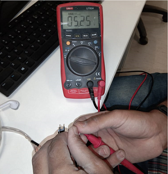
Voltage Across LED Strip
Current Across RED LED
The current is measured 47mA which is multiplied with 5 Volts is equal to 235mW
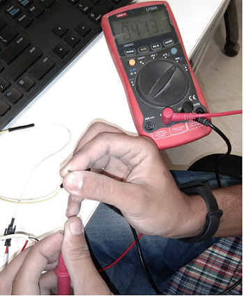
Pogram For Green LED
Green LED
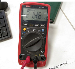
Current
The current is measured 21.46mA which is multiplied with 5 Volts is equal to107.3mW. Same procss is used for other colors too.
It's all about this Week assignment
Click Here for Downloading this week files
.png)