
|

| Sukkur IBA University Khairpur Campus Merit, Quality, Excellence |
Week - 3
Computer-Aided Design
Assignment
Model (raster, vector, 2D, 3D, render, animate, simulate, ...) a possible final project, and post it on your class page.
2D and 3D Modeling
There are different software for 2D and 3D Design.
2D Design
•Raster : GIMP, Photoshop, MyPaint, Krita, ImageMagick, GraphicsMagick.
• Vector : Inkscape, lodraw, Illustrator, CorelDRAW, Scribus, QCAD, FreeCAD.
Difference between vector and raster
There are different software for 2D and 3D Design.The main difference between vector and raster graphics is that raster graphics are composed of pixels, while vector graphics are composed of paths. A raster graphic, such as a gif or jpeg, is an array of pixels of various colors, which together form an image. link
Pro's and con's of vector and raster
vector pro's
• Data can be represented at original resolution without generalization( no resizing data)
• Graphic output is usually more aesthetically pleasing (looks better for example it is less block like and gives better representation of the shape)
• Most data is in vector format so there is no data conversion
• allows for efficient coding of topology (for example proximity and network analysis )
vector con's
• The location of each vertex needs to be stored explicitly
• Algorithms for manipulative and analysis functions are complex and may be processing intensive. Often, this inherently limits the functionality for large data sets, e.g. a large number of features.
• continuous data is not effectively represented for example elevations
• Spatial analysis and filtering within polygons is impossible
Raster pro's
• The geographic location of each cell is implied by its position in the cell matrix.(for example bottom left corner)
• Due to the nature of the data storage technique data analysis is usually easy to program and quick to perform.
• The inherent nature of raster maps is ideally suited for mathematical modeling and quantitative analysis.(for example attribute maps)
• Discrete data (such as forestry stands) is accommodated equally well as continuous data, (e.g. elevation data), and facilitates the integrating of the two data types
• fixed resolution( can be good or bad)
• “remembers” the start and end points of a line
raster con's
• cell sizes determines resolution at which data is represented
• It is especially difficult to adequately represent linear features depending on the cell resolution.
• Since most input data is in vector form, data must undergo vector-to-raster conversion. Besides increased processing requirements this may introduce data integrity concerns due to generalization and choice of inappropriate cell size. link
3D Design
• Non-Parametric 3D Design: Rhinoceros 3D, ZBrush, Blender, SketchUp, TinkerCAD, 123D Design.
• Parametric 3D Design : Fusion 360, SolidWorks, FreeCAD, Creo, ONShape
GIMP
Gimp is a free and open source raster graphics editor used for editing and retouching images. I selected Gimp as my raster software and it was an opportunity to learn a new one.
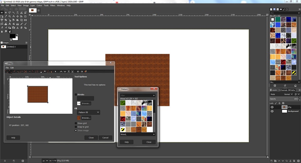
design in gimp final proposal
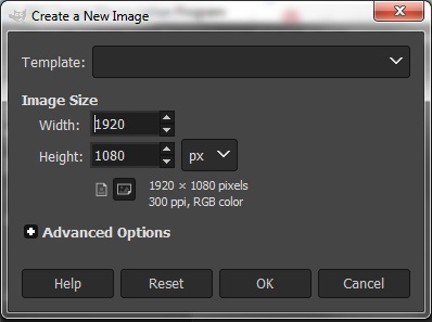
• Open the gimp
• Go to the file menu
• Press new to create a new image
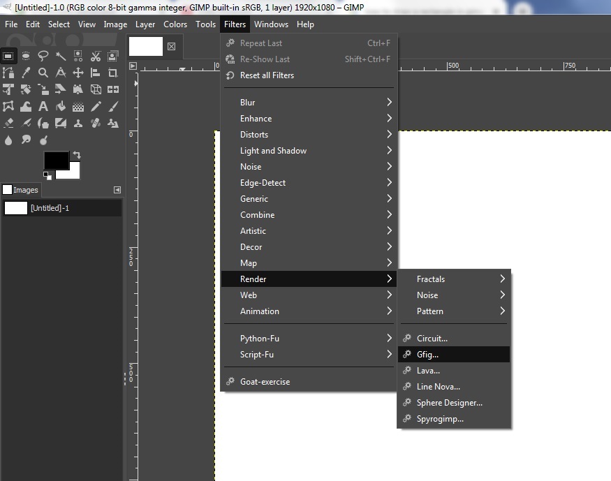
• Now go to filters
• Choose the renders and from dropdown menu select Gfig
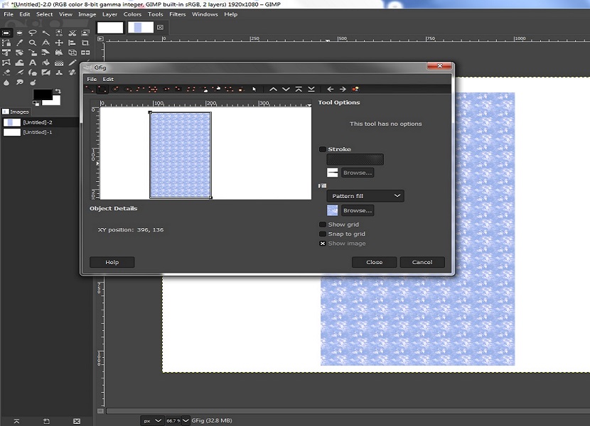
• Select the rectangle option
• Then drag down the rectangle and uncheck the stroke to remove outlines
• If you want to fill your rectangle choose fill to color fill or pattern fill.
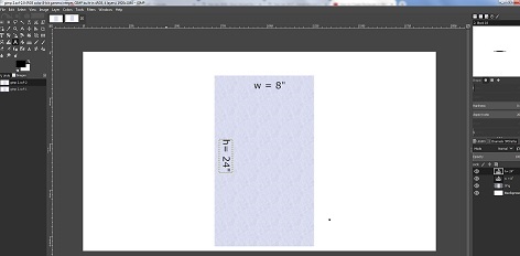
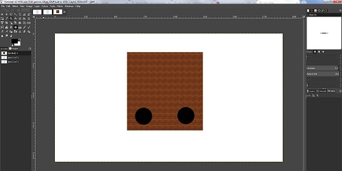
• Now for second part follow same steps
• For circle select ellipse tool to draw a circle
• After that right click on circle to fill with background color. link
INKSCAPE
Inkscape is a free and open-source vector graphics editor; it can be used to create or edit vector graphics such as illustrations, diagrams, line arts, charts, logos and complex paintings. I just scrabbled with Inkscape and made some proposal final project drawings by using many tools in Inkscape.
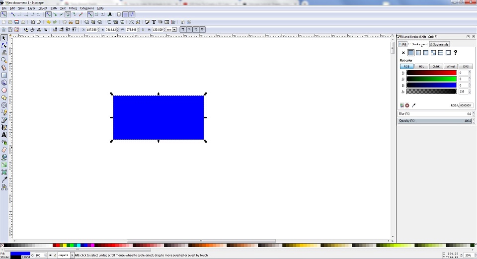
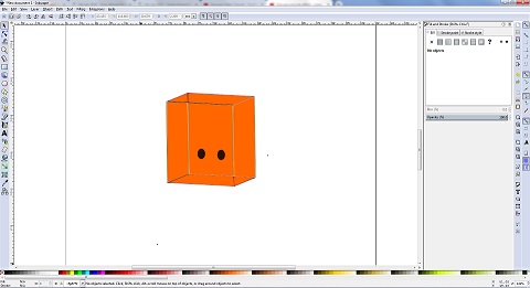
design in inkscape final proposal
• Open the inkscape
• Draw a rectangle
• Fill the color which you want.
• Than rotate rectangle as looks a cube
• Make a copy of that rectangle and drag it bottom side
• Now draw lines to complete a 3D cube.
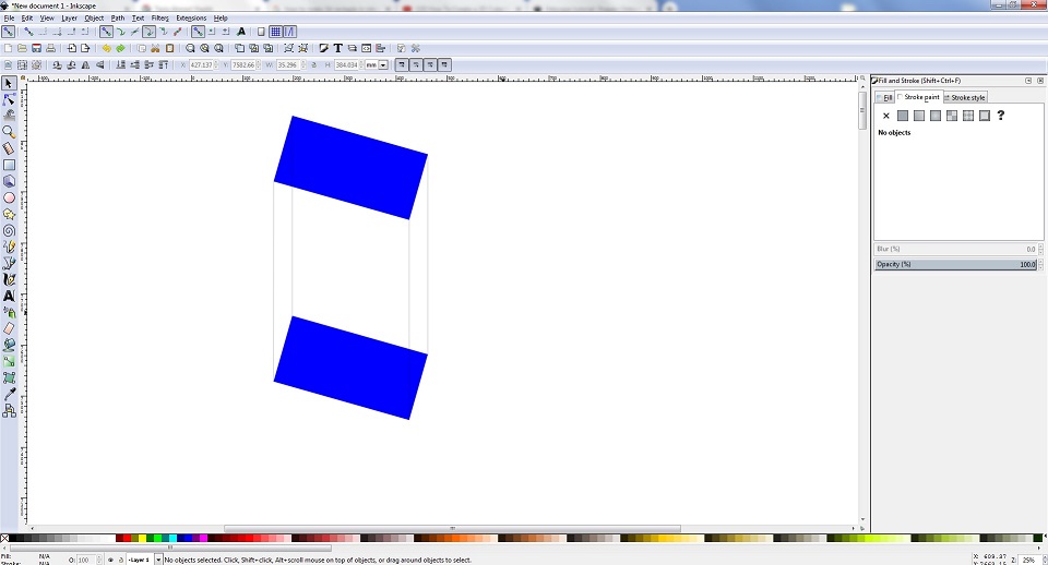
• After that select fill bounded areas tool to fill the 3D cube.
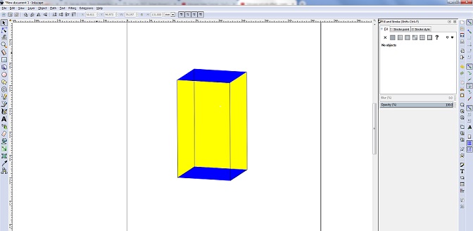
• For bottom part follow same steps • Now create circles for Distance sensor.
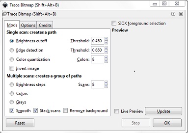
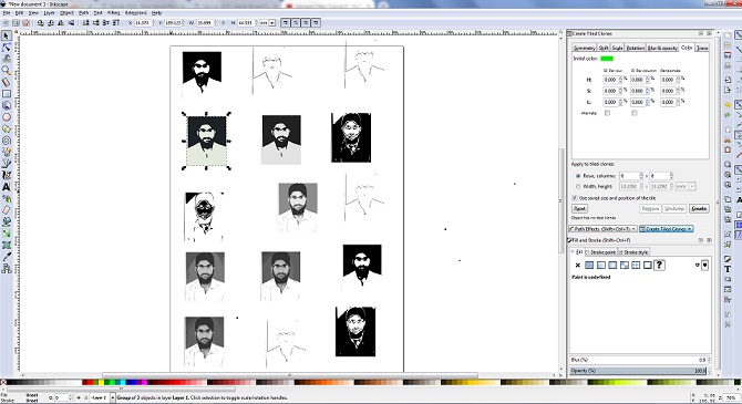
After that i took my old picture and traced its bitmap to create a vector file,i have changed some value of Brightness cut-off, Edge detection, Color quantization and got different results.
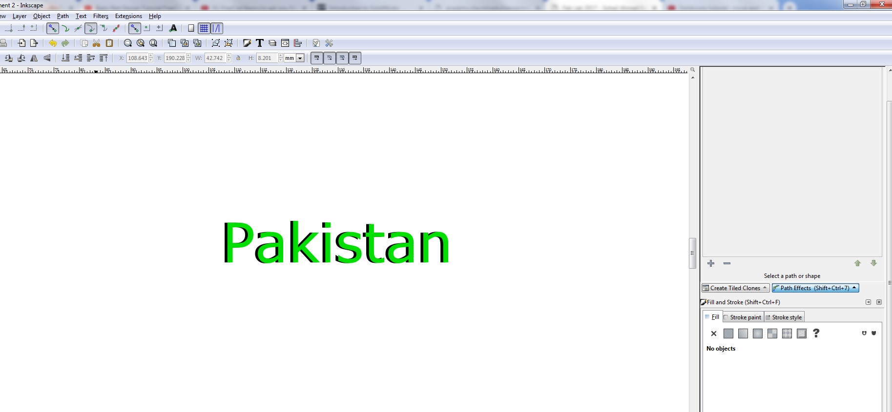
2.5D Text in Inkscape
•The first step is to make a custom view in the "View" menu. •Now Write a text you want by click on the "create and edit text object" or simply press F8. •To edit the text and make some change is it select the text and press "Shift+Ctrl+T", you will see a dialog box in which you can change the font and other details of the text. •After doing this create a dublicate of that text by right clicking on the text. and then go to the "Object" Menu and click "fill and stroke" and change the colour with some light colour. •Send that new layer to button by going to the "Object" menu and click "lower to button" or simply press "END" key from keyboard. •Now without deselecting press the arrow keys to move the lower layer. move it three or four times on any side you want and now you will get the effect of 2.5D text or some shadow of text.
SOLIDWORKS
Solidworks is another computer-aided design (CAD) and computer-aided engineering (CAE) computer program that runs on Microsoft Windows. It is widely used by many Engineers for making their designs. I am completely new to this software and i have started learning from the tutorials and practiced it.
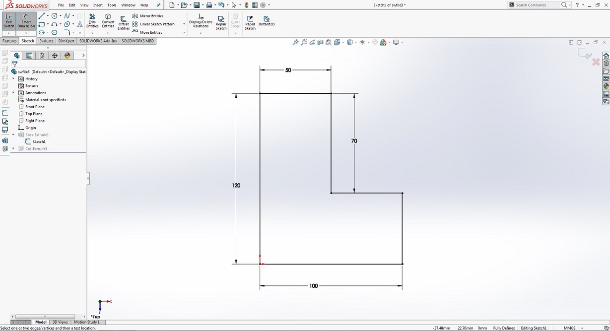
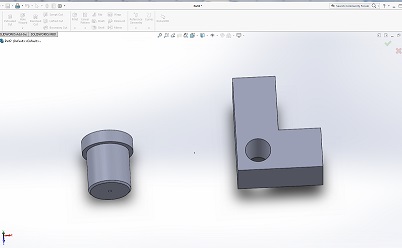
Making block
• Before you start creating sketches you must select plane or face where the sketch will be place on.
• When you done with sketch, adding features it is your next step. Select Feature>Extruded
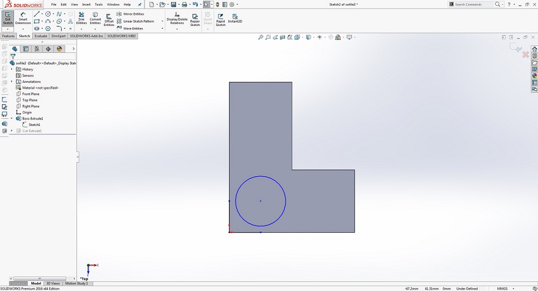
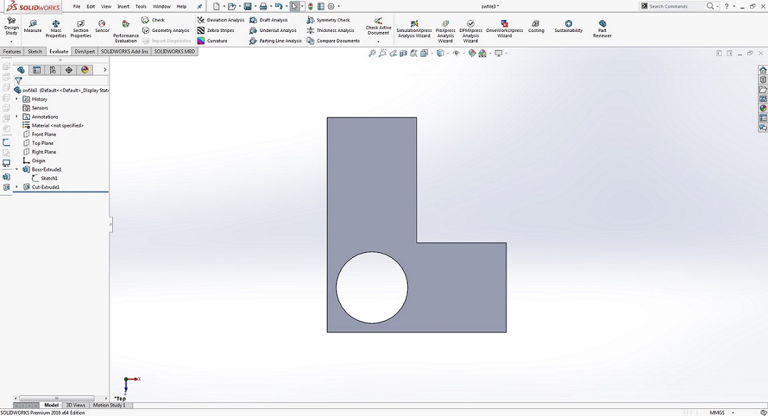
• After that Select Feature>Extruded cut and cut a hole for placing pin.
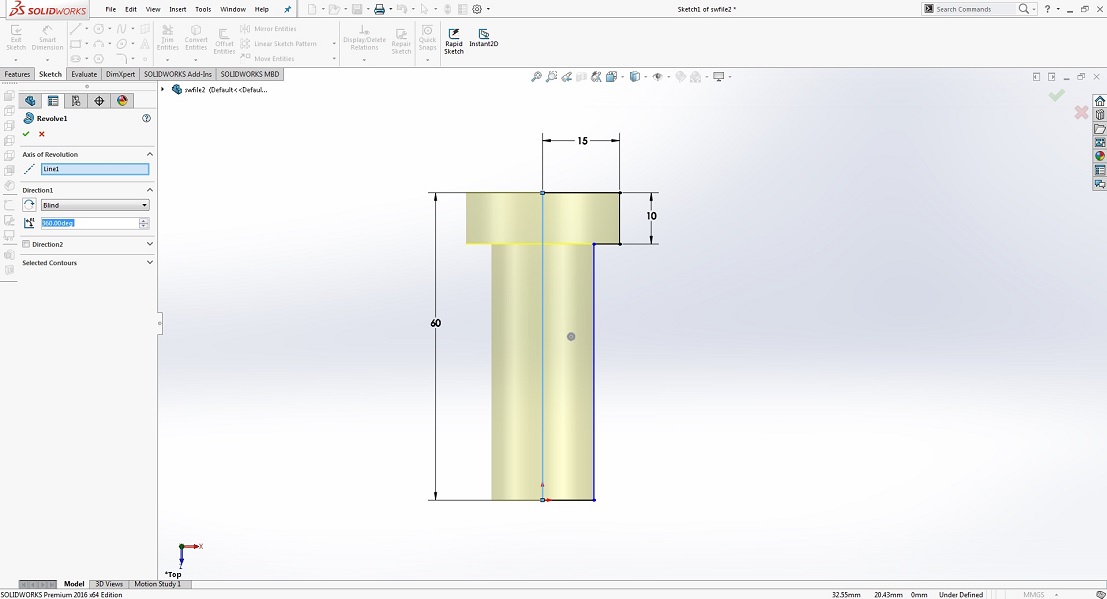
Making Pin
• First make a sketch for pin.
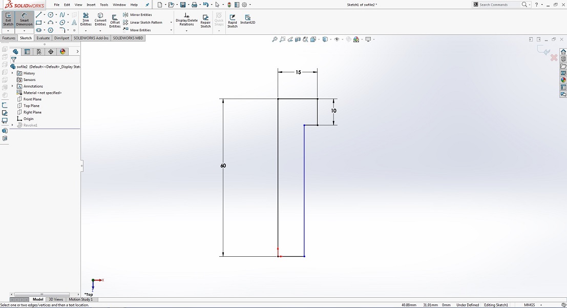
• After that Select Feature> revolve
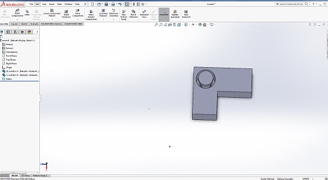
• Assembly is how all parts works together in assembly, checking for clashes and it functionality. First all parts inserted in assembly by Insert Component tool.
• Let’s mate this block and pin together, click Mate and select pin face and hole face, OK.
RHINOCEROS
Now I am trying to work in Rhinoceros 6.0, we can download its 90 Days trail version. it is new for me and i watched some tutorials for beginners and make a spiral stairs.
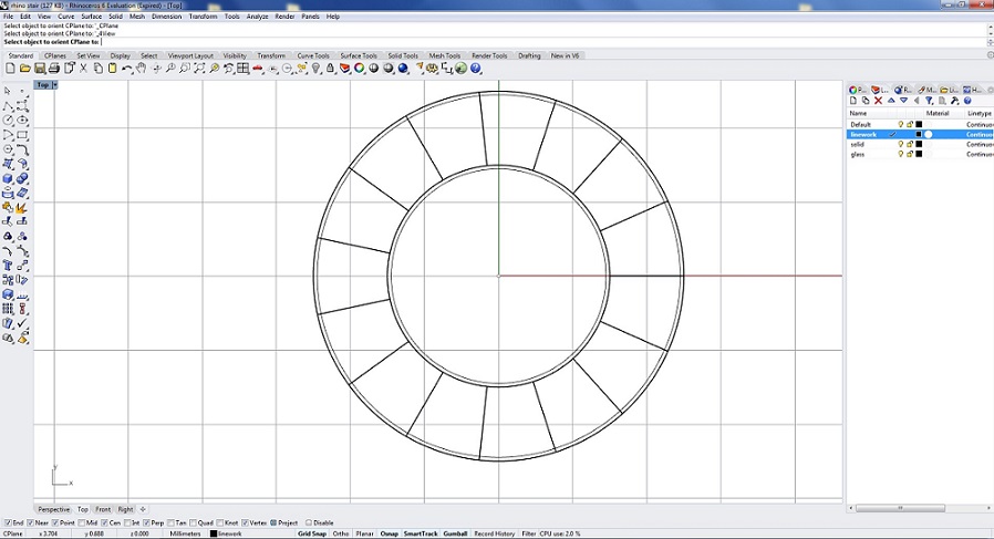
Making spiral stairs
• Open the rhino
• Make a new layer
• draw a circle with radius of 1.5 meter.
• Make offset 1 meter inward circle.
• Select both circle and divide in 15 segments
• Write SelPt command to delete points • Than SelCrv and select which curve you want and delete rest of all.
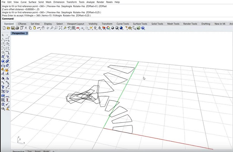
• After that write ArrayPolar command and select the curve and center of axis
• Than make 15 number of items and make 360 degree than select ZOffset 0.25
• Now select 15 curve and group them
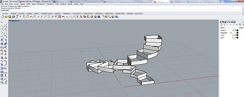
• For making solid stairs enter ExtrudeCrv command and 0.25 extrusion distance
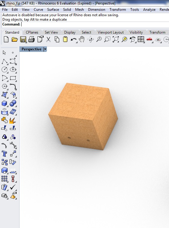
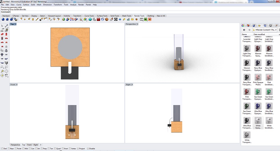
In Rhinoceros I have designed final project model, First draw the 2D model with basic drawing tools like rectangles, circles etc, and extrude them at desired height.
Making final proposal
• First go to tool bar open up solids tool and select 3D box for bottom part.
• Again go to tool bar open up solids tool and select round hole
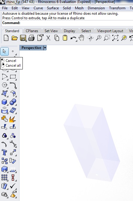
• Than make another 3D box for upper part
• After that go to Explode command to drag upper surface of 3D box to make a hollow box
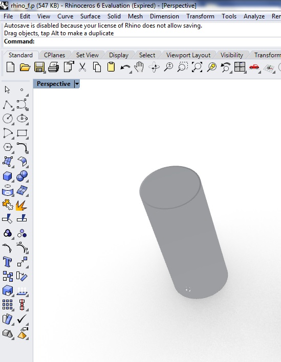
• Now go to tool bar open solids tool to draw a solid cylinder
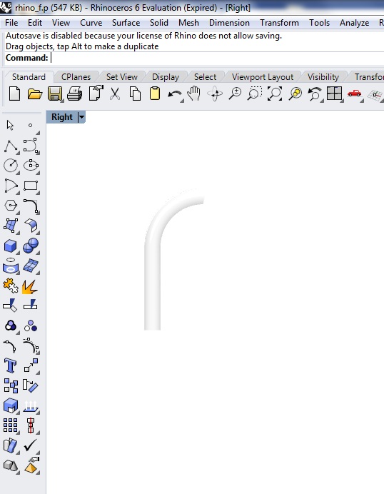
• For pipe, make simple curve and go to solids tool and select pipe than select end point of curve with required diameter.
Here is a final result of proposal
"Click here"to download all files of this week

Automatic Hot Water Dispenser by Tariq Ahmed Shaikh is licensed under a Creative Commons Attribution-ShareAlike 4.0 International License.
Based on a work at http://fabacademy.org/2019/labs/khairpur/students/tariq-ahmed/