
Fab Academy 2019 - Lucas Lim
My Final Project Electronics Design and Fabrication
My Final Project Electronics Design and Fabrication
My Final Project Phases :
Project
Conception
Project
Planning
2D & 3D Design,
3D Print & Laser Cut
Electronics Design
and Fabrication
Programming &
Testing of
Electronics
Project
Presentation
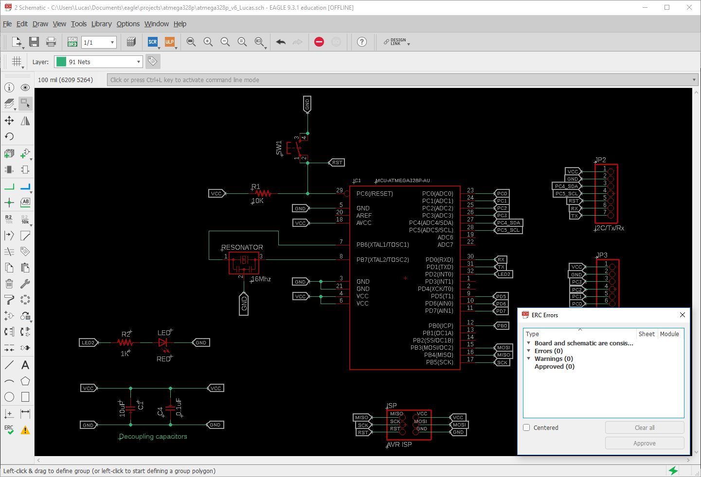
1. Microcontroller : Atmel ATmega328P :
For the microcontroller, this time round I opted to use the ATMega 328P which has more pins to cater to my needs and importantly it is compatible to the Arduino Uno Board which I use as a reference board for testing/development. The ATMega also provide more FLASH memory space.
I refer to the following online articles to design and build my first Arduino-compatible board :
- Arduino Pro Mini Schematic from www.arduino.cc
- Arduino UNO Rev3 Schematic
- online guide by Instructables.com on how to make your own Arduino Nano board
-
checklist on things to consider when designing a custom board, based on an Arduino
-
checklist on understanding Arduino UNO Hardware Design
2. Connectors and Microcontroller Pins selection :
I decided to use the vertical connectors this time as to save some horizontal space. Pins will be plugged in vertically.

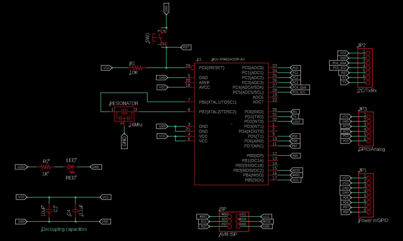
A I2C connector :
For the LCD display with an I2C adaptor, I have created one connector for I2C communication and place it at the top of my board.
I2C pins required :
- Pin 27 (PC4) (SDA)(required for I2C)
- Pin 28 (PC5) (SCL)(required for I2C)
- VCC
- GRN
A connector for AVR ISP Programming :
- MOSI (Pin 15)
- MISO (Pin 16)
- SCK (Pin 17)
- RST (Pin 29)
- VCC
- GRN
Pulling out a few more pins for the dust sensor module and buzzer and a couple more pins for future expansion needs.
3. Power Source :
A standard USB 2.0 port is capable of delivering 500mA (0.5A) while USB 3.0 port can deliver up to 900mA (0.9A) of output current.
Therefore I have selected to use a 5V 500mA power adaptor as the main power source for my electronic board. Two pins are allocated for VCC In and GND.
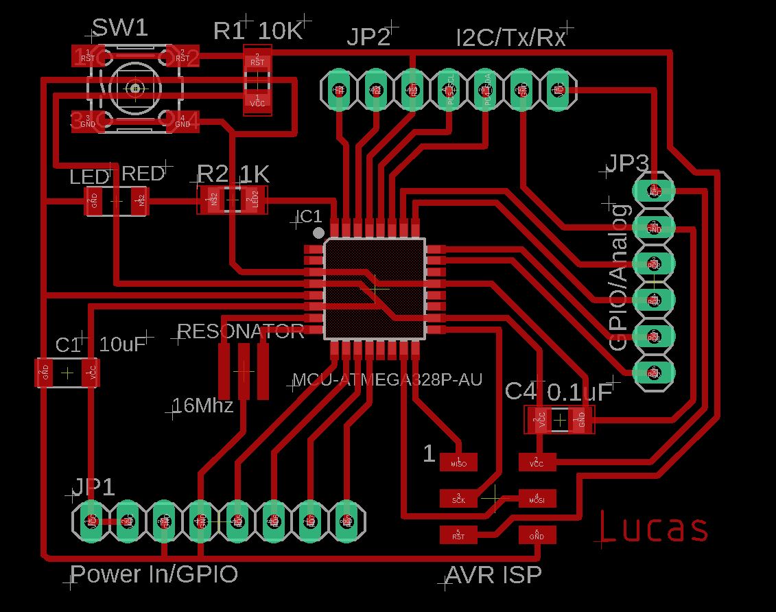
4. My components list :
ATMega328P x 1
Cap 10uF x 1
Cap 0.1uF x 1
LED Red x 1
Res 1K x 1
Res 10k x 1
16Mhz Resonator x 1
Button switch x 1
ISP header(2x3) x 1
Connector Header Through Hole (1 x 6) x 1
Connector Header Through Hole (1 x 7) x 1
Connector Header Through Hole (1 x 8) x 1


I spreading out the pin connectors as well as the other components for easier reach and connection of the wiring later on.
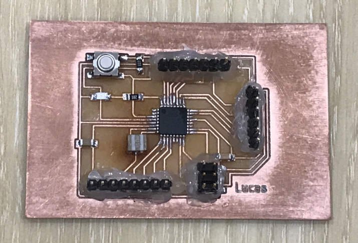
Building my own board : PCB etching using StepCraft 420 milling machine


The PMS 5003 sensor comes with a set of tiny (JST 1.25mm) connecting wiring. It is too tiny to be able to fit directly onto my PCB. Therefore I had modified the JST wires and fitted with 'Duport'. 2.55mm female headers so that it is able to connect onto my PCB.


I am using a AC 110-220 to DC 5V 500mA power adaptor as the main power supply for my dust sensor.
I cut and solder the red color and black color jumper wires to connect to the 5.5x2.1mm power jack and power switch.


For my future design, some areas of improvement includes :
1) Reducing the size of my electronic board.
2) Taking note of the number of wirings involve and its length. Some of my jumper cabled are log, some short.
3) In future, I hope to explore on bluetooth/Wi-fi connectivity, and data storage option like SD card reader.
4) Include one more capacitor and a 5V voltage regulator to regulate the power supply in.
5) Package : The plywood had burnt marks on the surface due to laser cutting. A acrylic material is much better, but when engraving words, it tend to has some 'white patches'... in the future will look at better way to package the final product; make it look more presentable and professional looking, both outside and inside. Aslo think of a better way to tidy up the wires inside.
Problems encountered :
a) While etching the traces : My cutting tool broke half-way. It is best to have a look at the tip of the cutting tool to make sure it is sharp before etching.
Another time, the cutting tool accidentally pulled up one of the traces. So I had made the width of my traces a bit wider this time.
b) Resonator : I had encounter issue with the resonator again. Had to re-work and solder back to make it work. However using the hot-air gun also melted the glue at the nearby connector. I switched to using internal 8Mhz clock at the moment.
c) Power jack/power adaptor : I had some issue with the 110-220 AC to DC power adaptor or the 2.1mm diameter. power jack. Had power in, but nothing shown on the LCD display...