Charlieplexing
A lil' introduction
What is Charlieplexing ?
Charlieplexing is a way to adress individually a number of LEDS to control them separately, from a less number of pins.
This can be useful for lots of things. You may need to display status information on a small microcontroller, but only have a few pins spare. You may want to show a fancy dot matrix or clock display but don't want to use lots of components.
In this case, I'm gonna use Charlieplexing to light up some LEDs and give some life to Grace's computer on the second page of my book :)
How is Charlieplexing possible ?
Controlling LEDs separately is possible because the pins from microcontroller have three different possible states :
- High (+ / 5V)
- Low (- / 0V)
- Input (x / disconnected)
The input state has a high impendance, so we can consider it as disconnected.
What is electronical impendance ? It is the measure of the opposition that a circuit presents to a current when a voltage is applied.
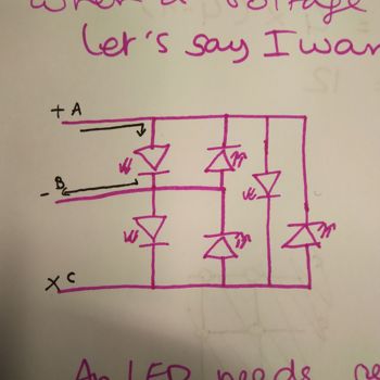
Let's try to light up one LED to understand how it works. For exemple, we want to light up the first LED of the circuit.
On our microcontroller we have three pins (A, B, C) that control 6 LEDs.
You can see on the schematic below that if you put the pin A on HIGH, the pin B on LOW and disconnect the pin C, the current flows a certain direction and lights up the first LED of the circuit.
How does it translate in real life ?
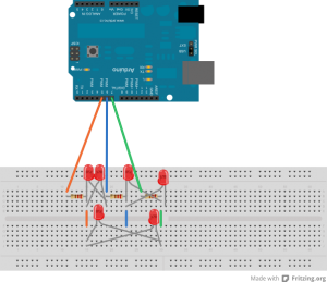
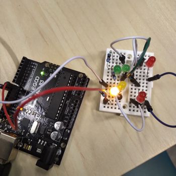
Let's test this with an Arduino to see it physically. Here is the wiring of the Charlieplexing.
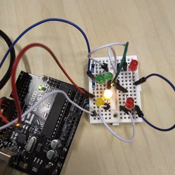
When you move the wires and connect and disconnect the pins, you can see (even without any line of code) that you'll be able to light up each LED individually.
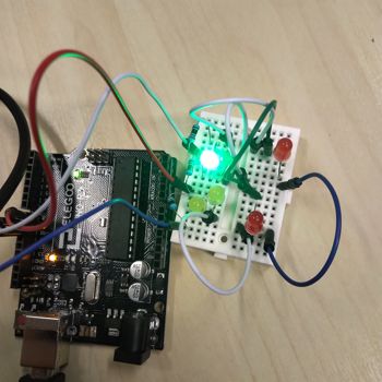
You've probably noticed I've put some resistors. They are necessary if you don't want your LEDs to die of their slow death due to to much power. You have two ways of putting resistors on a Charlieplexing circuit :
- When all the LEDs are the same : between the pins and the LEDs' circuit (like I did here)
- When the LEDs are not the same : Before or after each LED, because they might not need the same type of resistors.
Here is the table I made to know which state the pins have to be in order to control each LED :
| pin A | pin B | pin C | LED |
|---|---|---|---|
| LOW | HIGH | X | 1 |
| HIGH | LOW | X | 2 |
| X | LOW | HIGH | 3 |
| X | HIGH | LOW | 4 |
| HIGH | X | LOW | 5 |
| LOW | X | HIGH | 6 |
How do you know how many pins can control how many LEDs ?
There is a simple formula that helps you calculate that, N being the number of pins : LED = N * (N-1)
So you can understand it better, here is an exemple. Let's say you want to use 4 pins.
N = 4
LEDs = 4 * (4-1)
LEDs = 12
SO, for 4 pins available, you can control up to 12 LEDs.
If you want to understand better, do not hesitate to watch this great tutorial I found on youtube and that helped me a lot understanding all this :)
Wanna try by yourslef ?
Here is the link to my file, feel free to download it and create your own shapes :
| Name of the document | Link to download |
|---|---|
| Charlieplexing using a microcontroller | https://www.youtube.com/watch?v=y4f3FxIT9EI |
| How to Charleplex RGB LEDs | https://www.youtube.com/watch?v=AYV717iQsXo |