Exercise 9. 🔊👂 Input Devices 💡 👀 🌡 ✋
At the end of this exercise, I should be able to:
1. Probe an input devices and measure its signal (analog or digital).
2. Design, mill, stuff and program a circuit board for an input device (sensor).
3. Measure something by adding a sensor to a microcontroller.
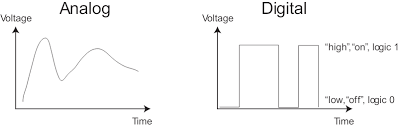
TWO key differences between analog and digital signals are:
1. An Analog signal is a CONTINUOUS signal that changes over a time period while Digital signal is a DISCRETE signal that carries information in binary form.
2. A sine wave form represents analog signal while a square wave represents a digital signal.
📌📍Probe an input devices analog and digital signals (Group assignment)
For the Group Assignment, we are to probe an input device(s)’s analog and digital signals.
For this assignment, we decided to probe:
1. Ultrasonic sensor HC-SR04 that produces digital signal
2. Temperature/humidity sensor DHT11 that produces digital signal
3. Light Dependant Resistor (LDR) that produces analog signal.
To simplify the workflow without making new board, ARDUINO UNO board is used for each of the sensor and the programming is done in Arduino IDE.
1. Ultrasonic sensor HC-SR04🔊🔊
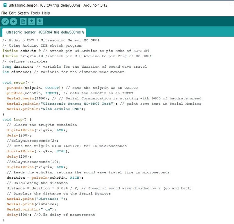
The details of the workflow in using ARDUINO UNO with Ultrasonic sensor HC-SRO4 can be seen in my individual group assignment below.
HC-SR04 sends trigger signal and receive echo signal. In the Arduino sketch below, the trigger signal is set HIGH (high voltage) for 200 ms and set LOW (low voltage) for 200 ms.
At the end of the trigger signal high, echo signal will be received in the form of high voltage, followed with a delay for 200 ms and then followed with 500ms delay where all the signals be at low voltage. Hence the total cycle is 900ms according to code that we have made.
 To measure the 2 signals (trigger and echo), we used the 2 probes and 2 channels on the oscilloscope. On the oscilloscope screen, Channel 1 (yellow line) is for Trigger and Channel 2 (magenta line) is for Echo.
Below is the video of the measurement using oscilloscope. It can be seen the square wave signals of the trigger and step signal of the echo.
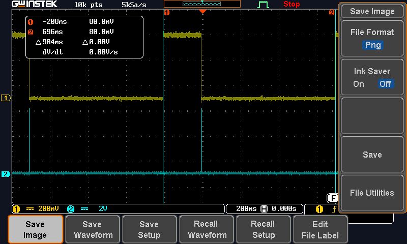
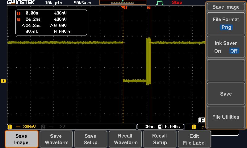
Below are the screen captures of the oscilloscope during the measurement.
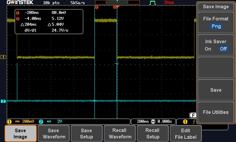 It can be seen that the difference between the HIGH and LOW trigger signal is 5 V and the duration of the HIGH trigger signal is 200 ms. These are the same as the code that we have made.
 The echo HIGH signal is within a very short time interval and happened as soon as the trigger signal drop from HIGH to LOW.
The ECHO signal is 5 V. The entire cycle is 900ms. These are the same as the Arduino sketch code.
Now I can really see the relation between the code and what happened when the code is executed into the MCU.
2. Temperature/humidity sensor DHT11🌡🌡⛈⛈
The details of the workflow in using ARDUINO UNO with Temperature/humidity sensor DHT11 and the arduino code can be seen in Ting Kok Eng's page.
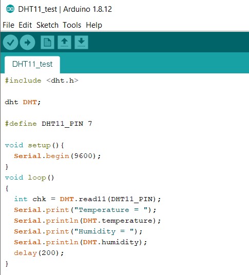
In the Arduino sketch below, we set a delay of 200ms for each measurement
 Below is the video of the measurement using oscilloscope.
Below are the screen captures of the oscilloscope during the measurement.
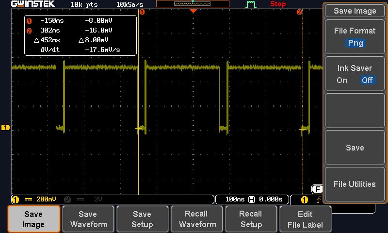
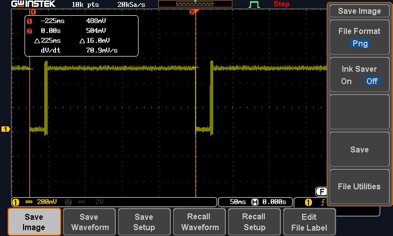
The duration of each cycle is 225 ms, eventhough the delay set in the arduino code is 200ms. This indicates that the measurement (transmiting and receiving) takes place within 25ms.
The HIGH signal is around 500mV and the LOW signal is around 10mV.
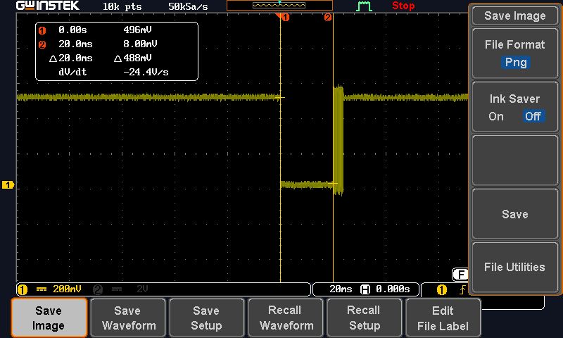
When we take a closer look at that 25ms interval at the beginning, after the LOW signal for 20 ms there's a burst of HIGH-LOW-HIGH signals within 5ms. On what these signals means, further reading of the data sheet of DHT11 should be done.
3. Light Dependant Resistor (LDR)🔦💡
The details of the workflow in using ARDUINO UNO with LDR and the arduino code can be seen in Ting Kok Eng's page.
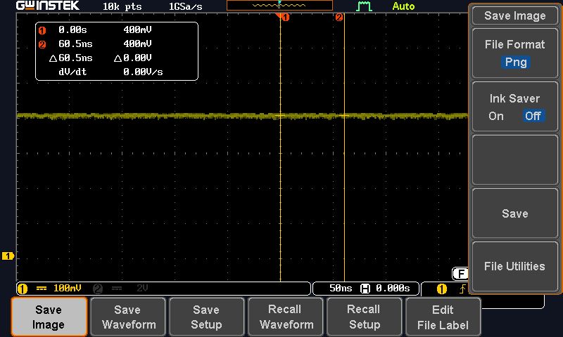
Below is the video of the measurement using oscilloscope. It can be seen how the signals gradually changed when the LDR is not covered (exposed to light) and covered (not exposed to light), indicating that it's an analog signal.
Below is the screen capture of the oscilloscope during the measurement when LDR not covered (exposed to light). It can be seen that the high signals is around 400 mV.
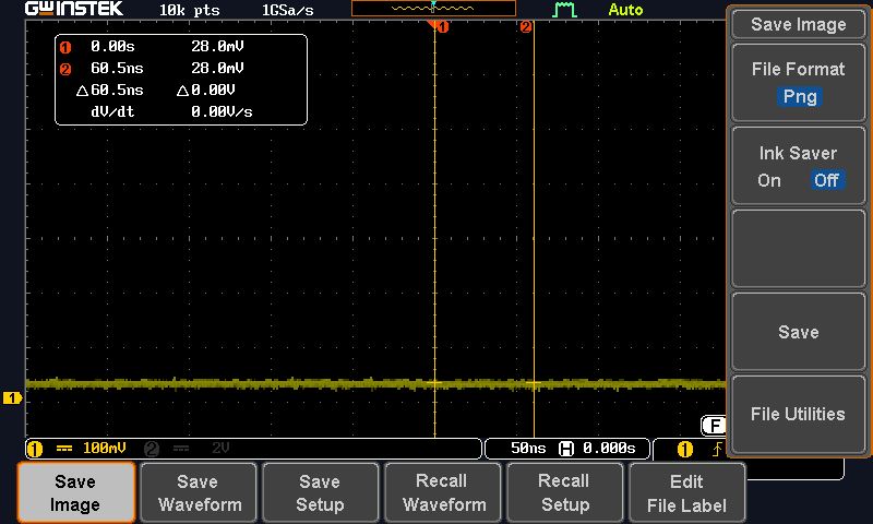
 Below is the screen capture of the oscilloscope during the measurement when LDR is covered (not exposed to light). It can be seen that the low signals is around 28 mv. And as can be seen in the video, the change in the signals changed gradually, hence analog signal.
Personal reflections:
Week 9 reflection really relevant to week 8 reflection. This week I use oscilloscope to check the performance of the microcontroller, and it is very useful because I can see and understand how the program and signals are related.
Add a sensor to a microcontroller board to measure something and read it (individual assignment)🌡🔊
For this exercise, I decided to add a temperature sensor to my newly designed board.
But before that I wanted to try to use ARDUINO UNO board first to familiarize myself with sensors and interfacing sensors to a microcontroller, before I make my own board and attach it to a sensor.
Experimenting with ultrasonic distance sensor on ARDUINO board🔊🔊
To do this, I use an ultrasonic sensor to measured distance and interface the sensor with an ARDUINO UNO board, following these 2 tutorials:
https://create.arduino.cc/projecthub/abdularbi17/ultrasonic-sensor-hc-sr04-with-arduino-tutorial-327ff6.
https://randomnerdtutorials.com/complete-guide-for-ultrasonic-sensor-hc-sr04/.
I started this experiment by using tinkercad circuit (refer to week 8 workflow) to simulate the processes before using the hardwares (board, ultrasonic sensor, male to female pin connector) and programme it.
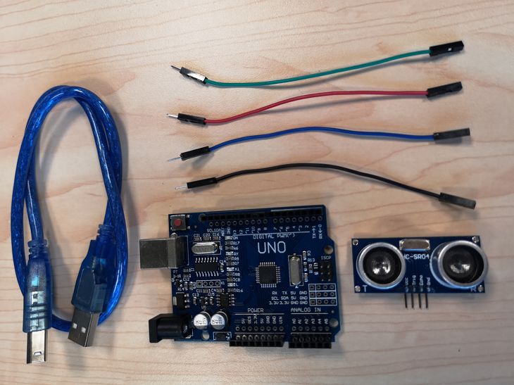
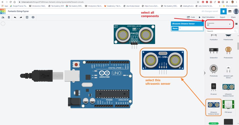
Below are the components that I will use:
 Before I start, I read the data sheet of the ultrasonic sensor HC-SR04 that I will be using.
Some important information gathered from the data sheet of the ultrasonic sensor are:
1. Operating voltage is 5V. Hence when I connect the sensor to Arduino board, it must be connected to 5 V Vcc instead of the 3.3 V.
2. Ultrasonic sensor signal is digital, hence the Trig wire and Echo wire must be connected to the DIGITAL PWM in Arduino board, not the analog pins
With these understanding, I started to create the simulation in tinkercad. Note that there are 2 types of ultrasonic sensors in the tinkercad database when all is selected. The one that I used in this exercise is the HC-SR04.
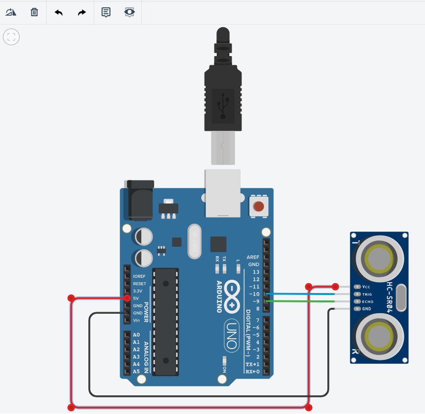
 Next is to connect the 5V Vcc and Gnd on Arduino board to the sensor (Vcc and Gnd). In the tinkercad, they are represented by Red wire (5V Vcc) and black wire (Gnd).
After that I select pin 10 in the Arduino board as the TRIGGER pin, hence connect pin 10 to TRIG on the sensor. It can be seen as blue wire in tinkercad. Note that any of the digital pin (pin 2-13) on the Arduino board can be used.
I select pin 9 as the ECHO pin, hence connect pin 9 to ECHO on the sensor. It can be seen as green wire in tinkercad. Note that any of the digital pin (pin 2-13) on the Arduino board can be used.
 Since my intention is just to familiarize, I just used available Arduino sketch code provided in the tutorial and modify the pin numbers accordingly. Below is the completed Arduino sketch code:
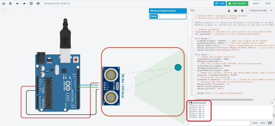
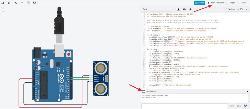 Now, I can start the simulation, by clicking the start simulation. But before that I click the serial monitor so that I can see the distance measured every 1 s. Below is the screen capture during the simulation:
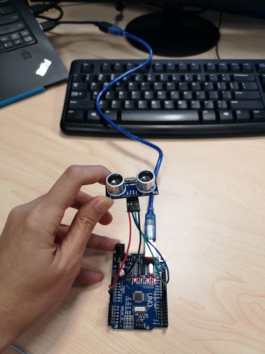
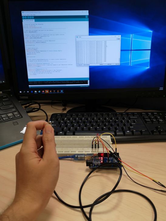
 Since the simulation went well. Now it is time to do it with the real components. To make things easier, I use the same pin 9 and 10 and also the same jumper wire colour as the tinkercad simulation. Here is the photo of all the components connected to my laptop via an usb cable.
 For the programming part, since I am using Arduino UNO board hence the steps are different from the previous week where I used ATtiny45. Below is the short workflow:
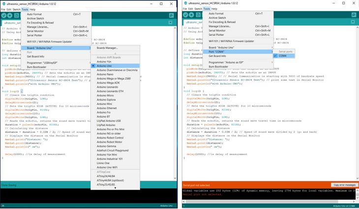
1. I need to choose Arduino Uno under Tools > Board > Arduino UNO.
2. Choose COM Port (usually it appears only one existing port), Tools > Port > COM.. If the port can’t be found, that means your Arduino board requires a driver. For my case, I downloaded the driver and install it and then the port can be found.
3. Copy and paste the same code used in tinkercad simulation into Arduino IDE. Save it as ultrasonic_sensor_HCSR04
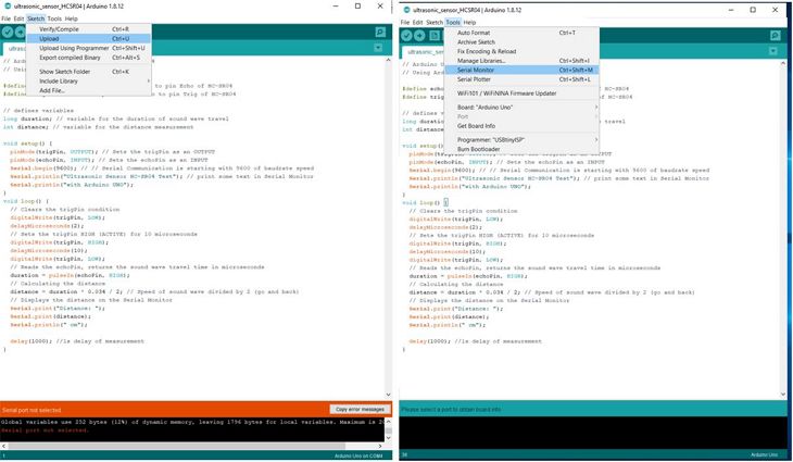
4. Upload the code by clicking Sketch > Upload
5. To display measurement data, use Serial Monitor by clicking Tools > Serial Monitor. The serial baud must be 9600 baud.
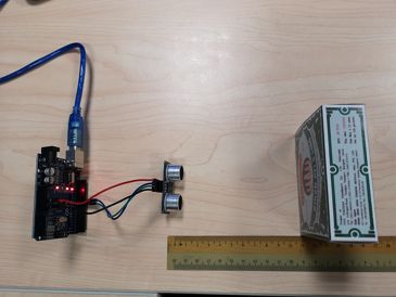
 To verify that the sensor works, I used a ruler to measure the distance between the sensor and an obstacle as shown below.
 In this video, it can be seen that the sensor works fine and showed readings similar to the ruler measurement.
Download the Arduino sketch program for this test here:
Experimenting with temperature sensor DS18B20 with ARDUINO board🌡🌡🌡
To do this, I use an ARDUINO UNO board, a breadboard, few jumper wires and a 4.7k ohm resistance and I follow this tutorial.
 To program the Arduino board, I use the Arduino sketch program from dallas semiconductor.
This Arduino sketch code require additional library (OneWire.h). The library can be downloaded from:
https://github.com/PaulStoffregen/OneWire
https://www.pjrc.com/teensy/td_libs_OneWire.html
Before I can upload the code into the arduino uno board, I encountered the below issue. The com PORT can not be detected in Arduino IDE. This is because I am using ARDUINO UNO with ATMega 328 chip as the IC and the driver for windows for this chip has not been installed.
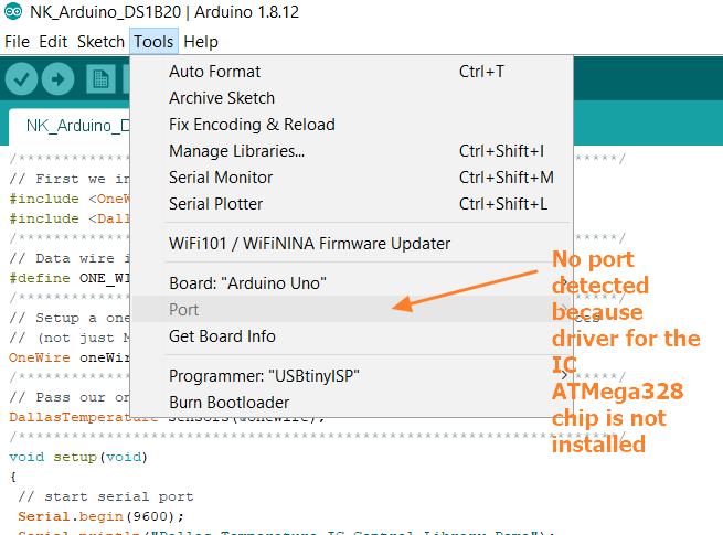 To solve this issue, I dowloaded the Windows CH340 driver from here and run the installer and the issue resolved.
In this video, it can be seen that the temperature sensor works fine and I used it to measure a warm water temperature around 55oC.
Download the Arduino sketch program for this test here:
Add temperature sensor (DS18B20) onto ATtiny 45/85 board🌡🌡🌡
In this experiment, I will use temperature sensor DS18B20.
 The data sheet can be read here.
Important information from the data sheet are:
1. Can be powered from data line using 3.0V to 5.5 V.
2. Measures temperature from -55oC to 125oC.
3. Requires only 1 port pin for communication.
4. Convert analog signal to digital signal within 750ms max.
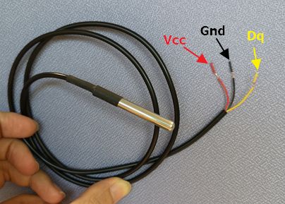
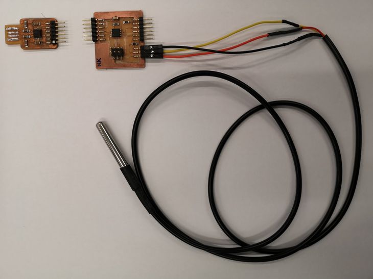
5. Refer the figure above, the red wire is Vcc, the black wire is Gnd and the yellow wire is Data (DQ).
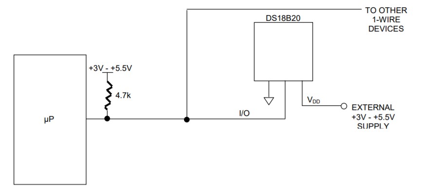
6. Strong pull-up on DQ line is required to assure DS18B20 has sufficient supply current during its active conversion cycle. The recommended way is shown in the figure below.
Below are the processes that I went through:
1. Designing the board
Based on the advice of my SP Fablab coach, Mr Steven Chew, I decided to use ATtiny 45 as the MCU for this board. It has 5 I/O pins that I can use for the program and has reasonable flash memory of 4K.
To design the board, I use EAGLE again. For this design, I need to have new component that is not available inside the "fab" library for EAGLE.
To create new component, one of the SP Fablab coach, Mr. Rodney Dorville taught me how to do it and there are also online tutorials on this:
1. https://www.instructables.com/id/Adding-Custom-Components-To-Eagle/.
2. https://dxarts.washington.edu/wiki/how-create-new-component-eaglecad.
The workflow in using EAGLE in drawing schematic and board can be seen in exercise 6.
The schematic of this new board is shown below:
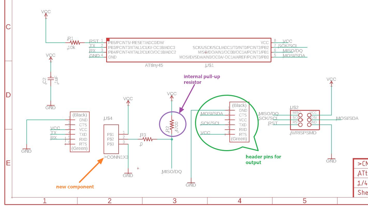 The new component indicated in the figure is a 3x1 header that will be used to connect the DS18B20 sensor to the board.
The internal pull-up resistor of 4.7k ohm is for the strong pull-up on DQ line.
The 6x1 header is based on the FTDI 6 header pin that I modify to suit for OUTPUT DEVICES. I planned ahead on the possible output devices for this board that is attached to the temperature sensor (I was being overly confident).
This board design is also intended for my final project that requires temperature sensor.
This time, I bravely tried to use manual routing in designing the board in EAGLE. It was a painful experience where I spent at least 8 hours. But the satisfaction when everything is routed nicely and no errors is undescribable.
One thing that I could do better is to use 16 mil trace line instead of 12 mil trace line.
Below is the board design:
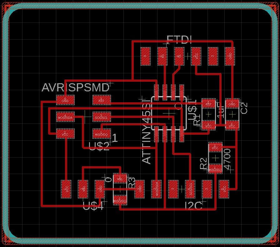 I have to resort with using 1 zero ohm resistor to allow one trace line underneath it. I have tried many different routes and this is the one that requires the least number of zero ohm resistor.
After designing the board, I created the .png files for the traces and for the cut-off just like in exercise 6.
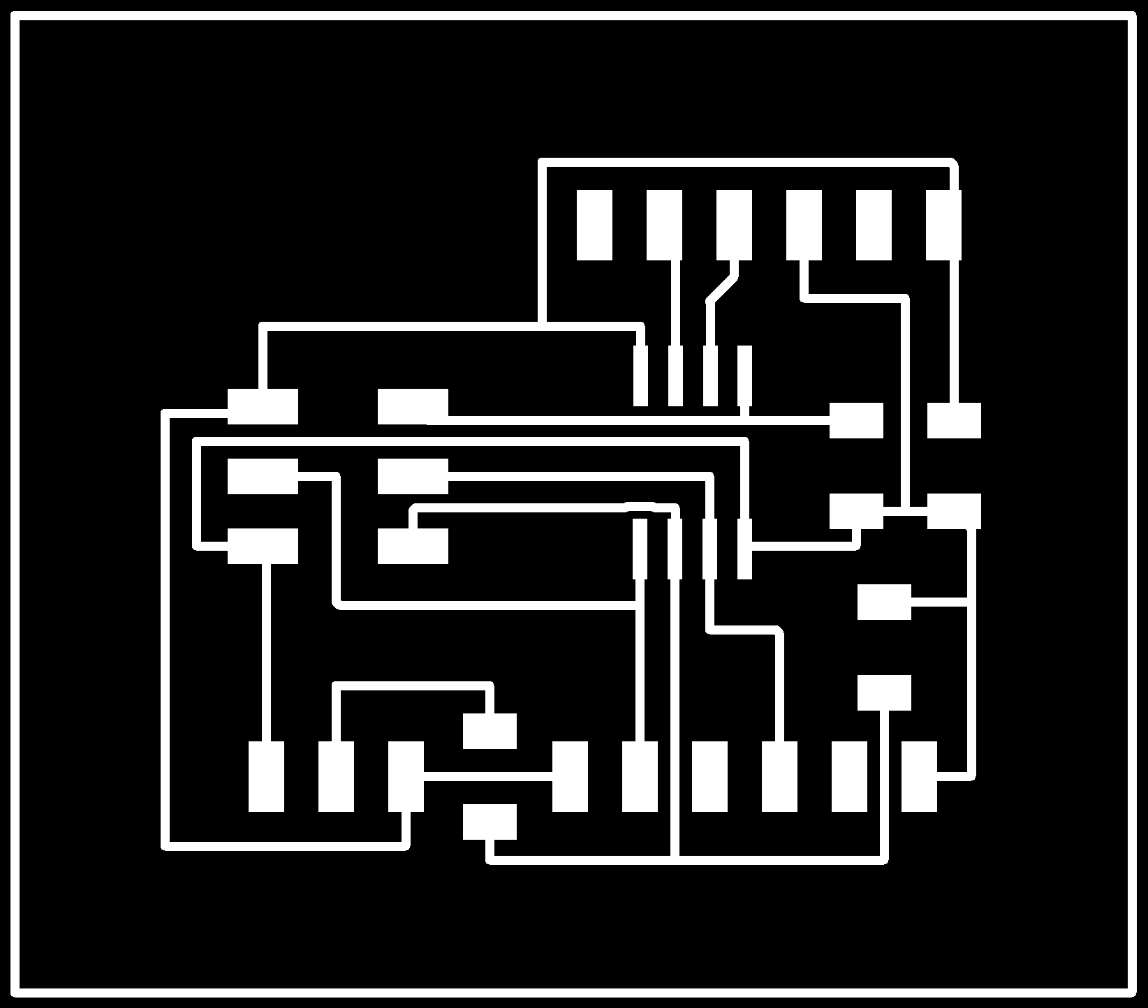
Download the schematic, board files in EAGLE and also trace and interior cut-off .png files below:
2. Milling and stuffing the board
I use mods again for creating the gcode file for milling. The same setting in mods as exercise 6 is also used here.
The end-mill I use for the trace is the same as exercise 6, which is V-shaped 0.1mm 10 degree angle. For the outline cut-off I use 0.8 mm flat end-mill.
This time, I really observed the condition of the end-mill tip. I compared at least 5 of the same type and select the most pointed tip (not yet broken). And this time around the milling process for the traces was smooth. Only when I cut-off the interior, the 0.8 mm end-mil brake half-way. But I can just restart the milling after putting in place a new mill and re-calibrating the z-axis.
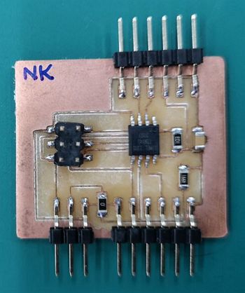
Stuffing the board with SMD this time was a challenge. I short circuit the ATtiny 45 because of too much solder hence I decided to mill a new board and remove all the dead copper in between any traces. With this board, I can soldered better and avoid making any short-circuit. I also check the continuity every time I finish soldering one component. This is a good practice as advised by the SP Fablab coaches. Below is the picture of the stuffed board:
3. Connecting the sensor, programming and testing
I connected the sensor by joining each wire from the sensor with jumper cable. The joint wire were soldered and covered with heat shrink. I learnt this from this tutorial.
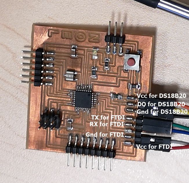
Below is the picture of the sensor DS18B20 connected to the board and also the FTDI board that I will use to receive the signal and read the temperature.
 To program the MCU, I use the same arduino sketch code as like when I experiment using DS18B20 with ARDUINO UNO.
But unfortunately, these library sizes is 5K bytes and ATtiny 45 only has 4k bytes flash memory.
After further discussion with SP Fablab coaches, I changed the IC from Attiny45 to Attiny 85 that has 8K bytes flash memory.
To replace the IC, I learnt to use the hotair rework station aka hotair gun. Mr Steven taught me and demonstrated in front of me on the use of the hot air gun and tweezer to replace the SMDs. Besides that I also further read the tutorials on these here.
Besides that, I also encountered issues where there were many short-circuits on my board (some of the Vcc are connected to the Gnd) due to:
1. In schematic, the "clearance" between wire-to-wire and wire-to-pad are set to 12 mil. I should set to 16 mil.
2. In schematic, the "size" mimimum width is set to 12 mil. I should set to 16 mil.
3. In mods. I set to one pass only when milling the traces. I should set at least 2 passes hence the gap between the active copper and dead copper is larger.
4. Bad soldering hence bridges between active and dead copper. I should remove the dead copper near to the active copper.
I noticed these short-circuit netween the active copper and dead copper only after I connect my ISP and my board to my PC using an USB cable. As the result the USB cable is fried and can't be used anymore. When I used this USB cable to connect an ARDUINO UNO board to PC, IDE can't detect the com PORT.
So I decided to remove all the dead copper and rework any bad observed bridges. Below is the end result.
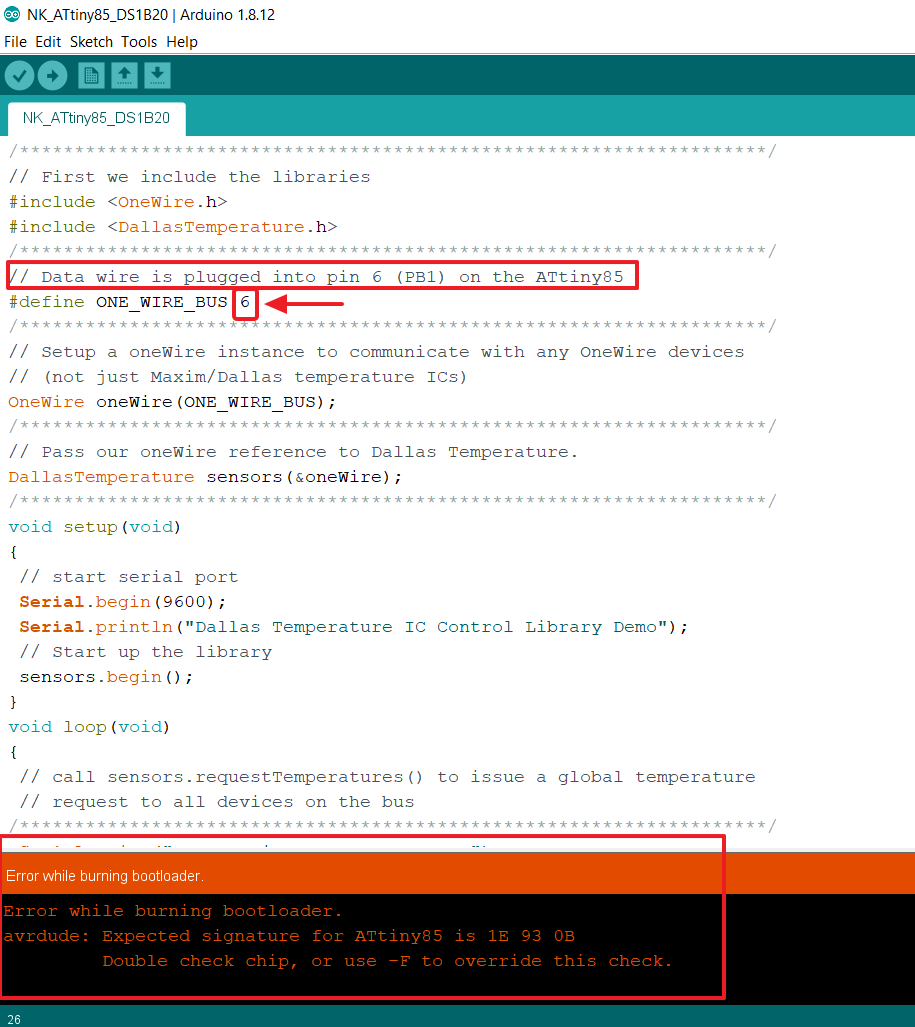
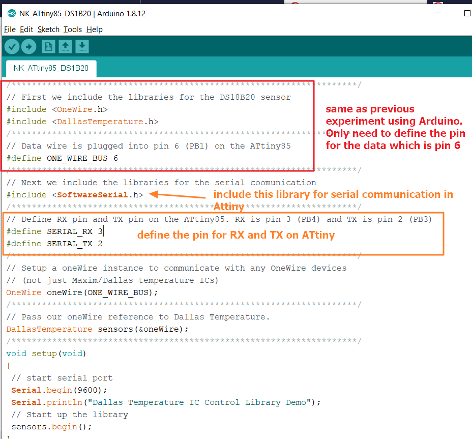
 The arduino code that I used for this, is the same as the one I used for ARDUINO board. The only modificatio is the PIN number is PIN 6 instead of PIN 2 in UNO board.
But when I want to burn the bootloader, error message as shown below appeared.
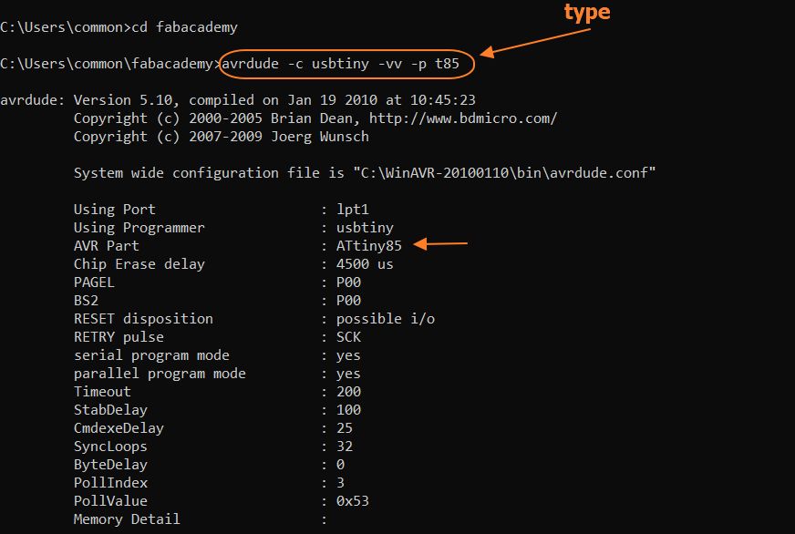
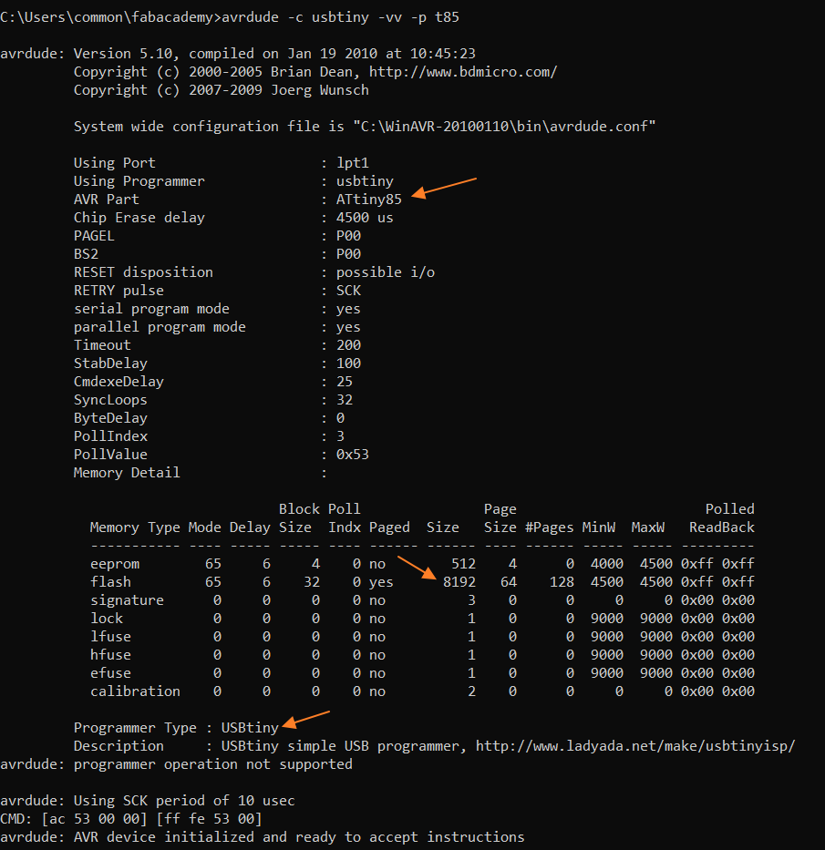
As advised by Mr. Steven, one of the SP Fab Lab coaches, I must check using avrdude from terminal to verify. Likely that the ISP programmer board can't interface with my At85 board. So as per advice, I typed the below on command prompt and the results are shown on the 2 figures below
avrdude -c usbtiny -vv -p t85
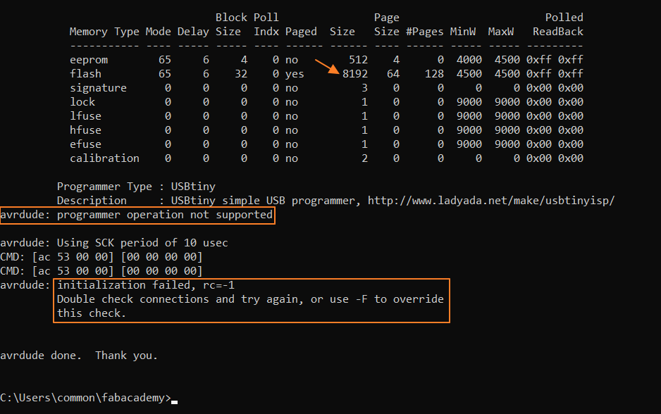
Similar results as when using ARDUINO IDE, initialization failed.
To rule out that the issue is not with the ISP, I used the ISP to program my hello board and the ISP work fine, it can program the hello board.
It seems the issue is with the new board (checking the continuity again).
I read one article on this issue, below is the article:
https://learn.sparkfun.com/tutorials/tiny-avr-programmer-hookup-guide/discuss
and follow the suggested step number 2, which is to connect to another USB port and/or different computer and the STEP WORK.
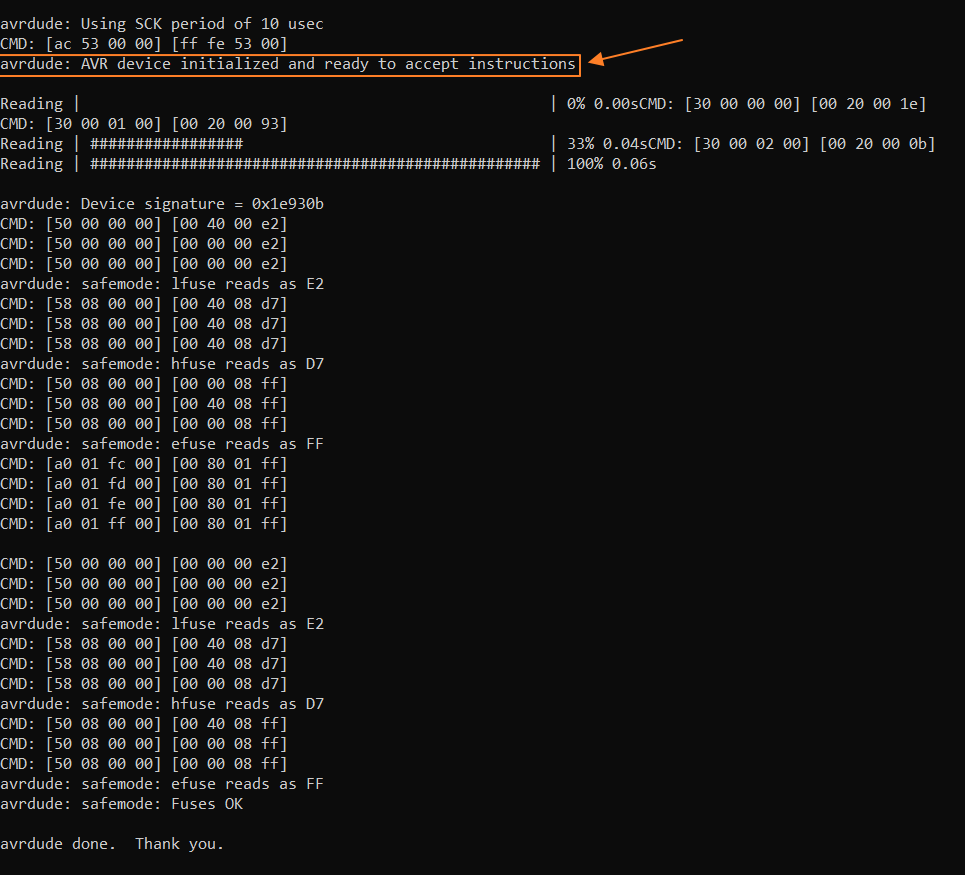
Now my board can work....SUPER HAPPY. Below is the screen capture of the avrdude to show that the ISP board now can communicate with the Attiny85 board.
I prepare the same arduino code in arduino IDE and set the "board"; "chip" and "programmer" accordingly before burn the bootloader.
I also defined the data pin for the temperature sensor as pin 6 and the TX as pin 2 and RX as pin 3.
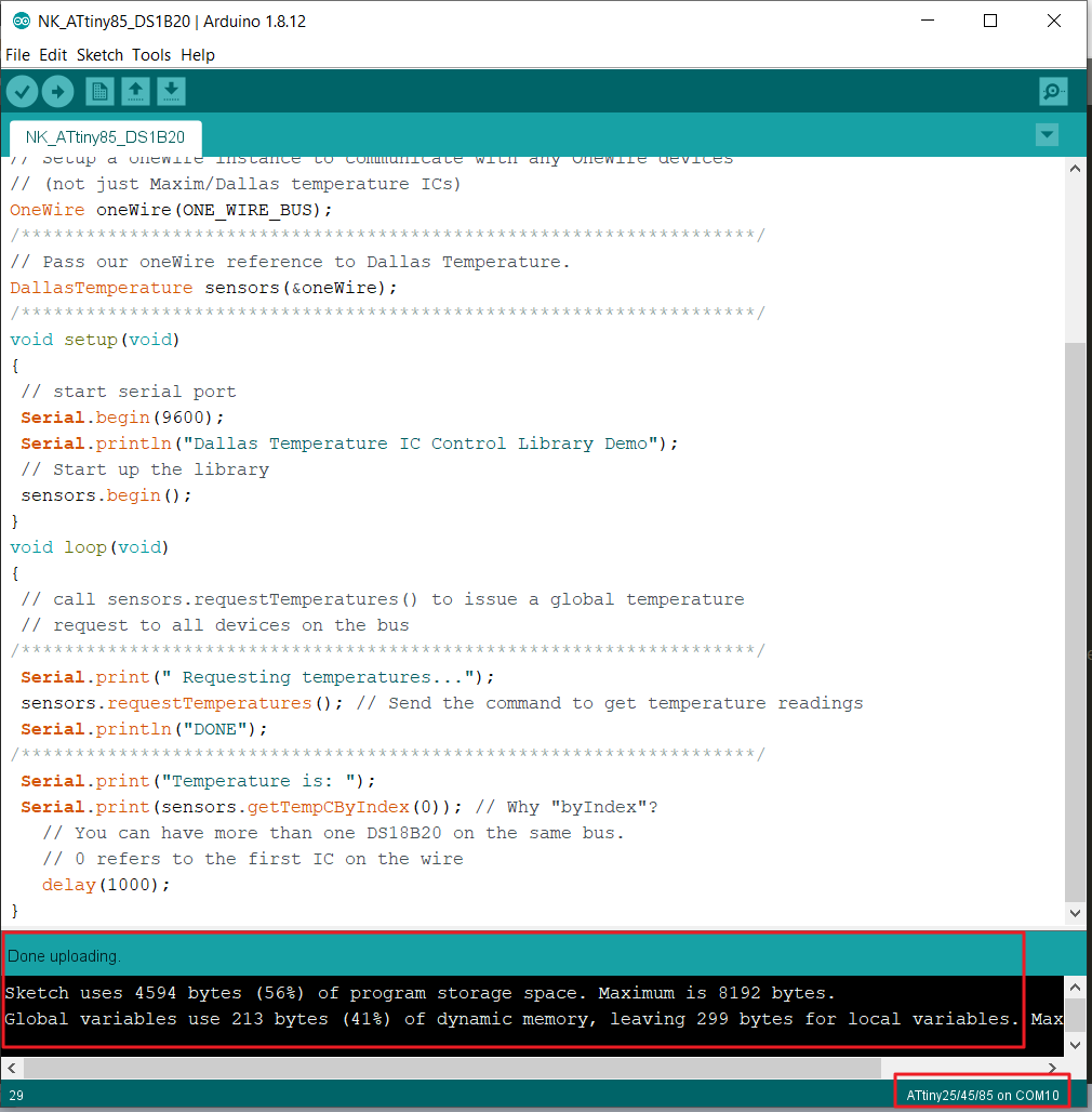
Now it is time to upload the sketch code onto the MCU. I failed many times because during uploading the program, the DS18B20 Temperature sensor is connected to my MCU board. After researching for days, I found this important information: "When the temperature sensor is connected, you will not be able to program the microcontroller using ISP. The sensor must be disconnected before programming the microcontroller. And finally, the uploading of the arduino skectch code is successful as shown below:
to download the arduino sketch code .ino
After succesfully uploading the program to the MCU, I connected the DS18B20 temperature sensor to the Attiny85 board and I connect the FTDI.
UPDATE!!Add temperature sensor (DS18B20) onto ATMega328 board🌡🌡🌡
I continue this work using a new board that I designed and fabricate for my final project.
The details of the design, production, programming of the board can be seen in the final project page HERE.
For the DS18B20 temperature sensor, I uploaded the same code to my ATMega 328 board as used in the Arduino.
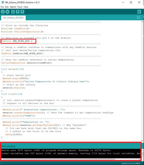
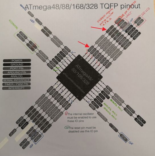
Eventhough my DQ pin is pin number 32 (PD2) I used the same pin number as Arduino Pin number (pin 2) because for the programming in Arduino IDE, I will define the ATMega328 board as Arduino UNO.
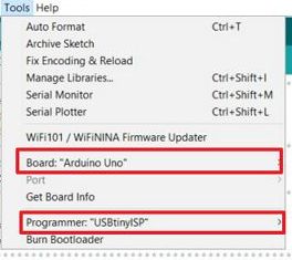
 To upload the program onto the board, I used Arduino IDE and set the board as Arduino UNO and use programmer "USBtinyISP".
to download the .ino code of the DS18B20 for ATMega328 Board.
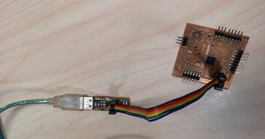
After uploading the code, I disconnect the USBtinyISP and then connect the DS18B20 sensor and FTDI board for the TX/RX communication so that I can use ARDUINO IDE Serial Monitor to see the reading results.
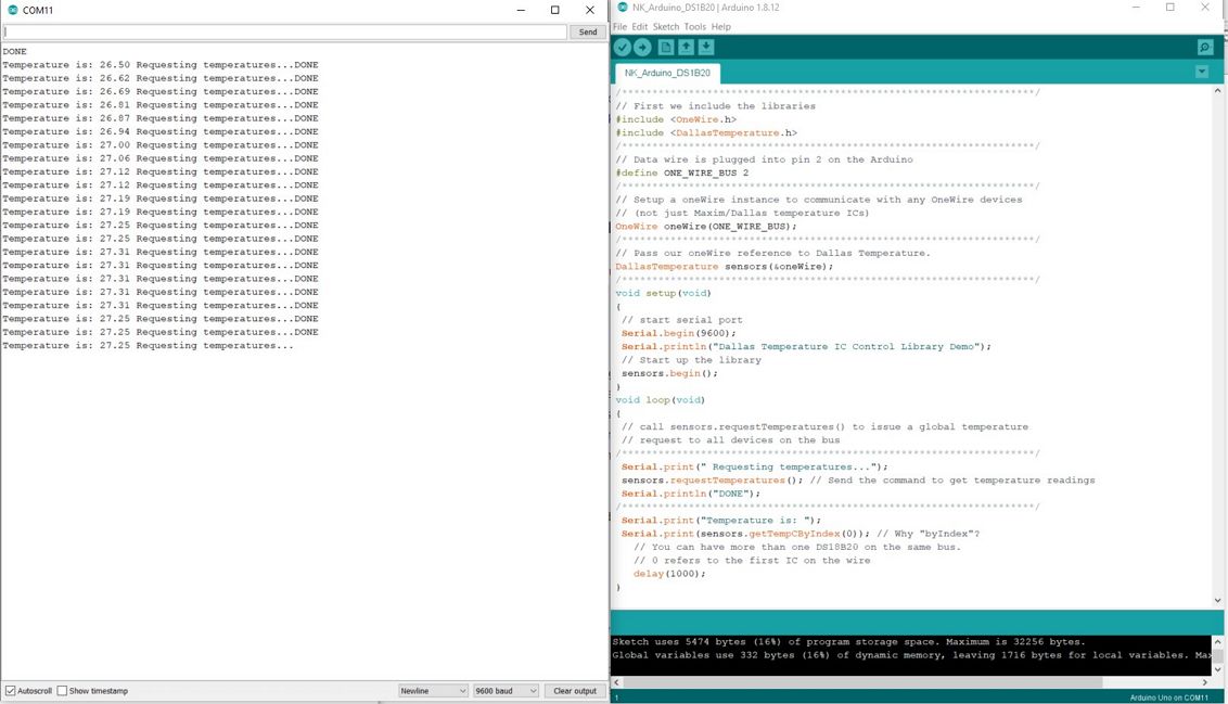
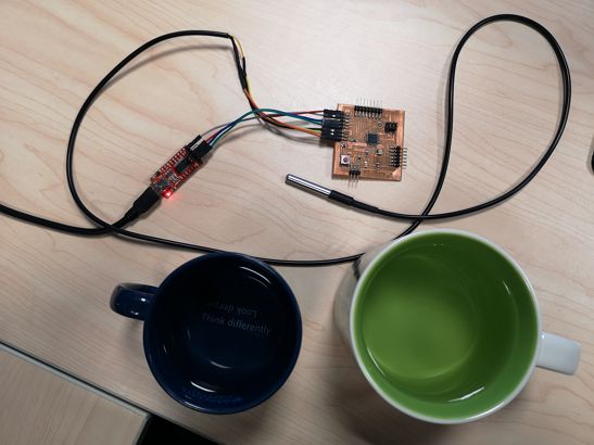 And then I connect the FTDI board and open Arduino IDE Serial monitor and now I can see the reading results.
And below is the video where I used the system to measure 2 different water temperature. The one on the left (blue mug) is hot water (around 70 degree Celcius) and the one on the right (green mug) is at 35 degree Celcius