IV. Soldering the components
Documenting the soldering part is not so exciting. I don’t go detailed in this section.
The PCB is designed for 1206 sized smd components. I had 0805 sized on stock, so I decided to use these.
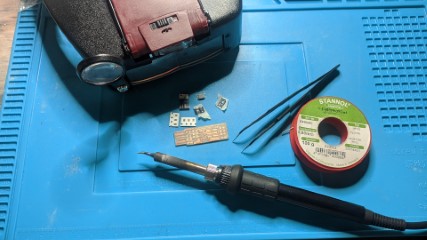
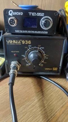
These are the tools I’ve used
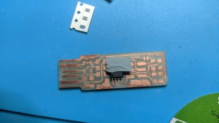
I started soldering the ATTiny on the PCB.
Normally I would just make solder on one pad, solder one pin of the chip and align it.
But this kind of pcb is not so easy to solder and overheating will result in lifting up the copper from the pcb. So, I decided to fix the ATTiny with a peace of tape.
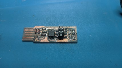
After the hardest part was finished, I’ve soldered the rest.
It’s important to check the polarity of the smd leds before soldering.
At lighthouseleds.com is good overview about that.
And the polarity of the zener-diodes are important, too. The cathode of the diode is marked with a stripe.
It’s nearly impossible to get exact the resistors, which are listed in the BOM of the FabTinyISP.
So I changed the mentioned 499 Ohm resistors to 470 Ohm and the 49 Ohm to 47 Ohm.
Well done....cheers… !!!
But I have to say, that I’m not convinced of this programmer. It sits much too loose in the USB-Port.
A piece of foam-tape under the PCB doesn’t makes it really better.
Just a little peace of carelessness, while programming a chip, could cause damages !
I’ll definitely prefer to use my programmer, which I already had on stock !