20. Project Development
This week I developed my pcb board and programmed it. I also began printing the final 3D prints. At this point in the project, I had two weeks, so I prioritised tasks on a daily basis. The first week I focused on completing the pcb board. The second week I worked quickly through molding/casting, then focused on 3D printing. The benefit of 3D printing is that I could let the jobs run and use this time to fix issues with the electronics. In terms of time management techniques, this is really how I worked: Managing tasks on a daily basis while keeping in mind the week's overall goal.
PCB Board 1
The first pcb I created used the NKK tilt switch. In Eagle, I assigned the following components,
- ATTiny 44 x1
- NKK Tilt Switch x1
- 5V Regulator x1
- 1Uf Capacitor 25V x3
- 100k Resistor x1, 10k Resistor x1, 150ohm Resistors x2 (for High Power LEDs), 200ohm Resistor x1
- 2x3 pin header
- 6 pin ftdi header
- SMD switch (for battery)
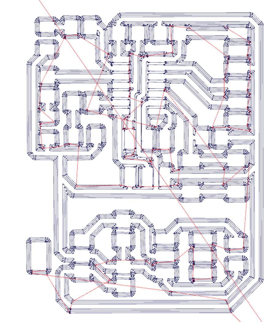
I would use the 5V regulator to reduce the voltage of the 2x3V battery to 5V. I created empty pads for the two LEDs and battery using similar components. With the routing tool, I set the tracks linking the capacitors, resistors and other components. It was important to consider the balance of the tilt switch in the overall form. I positioned most of the components to counter balance the weight of the batteries, with the tilt switch in a central position.
After exporting as a PNG from Eagle (then Photoshop), I worked in Fabmodules to enter the parameters as per Electronic Design week.
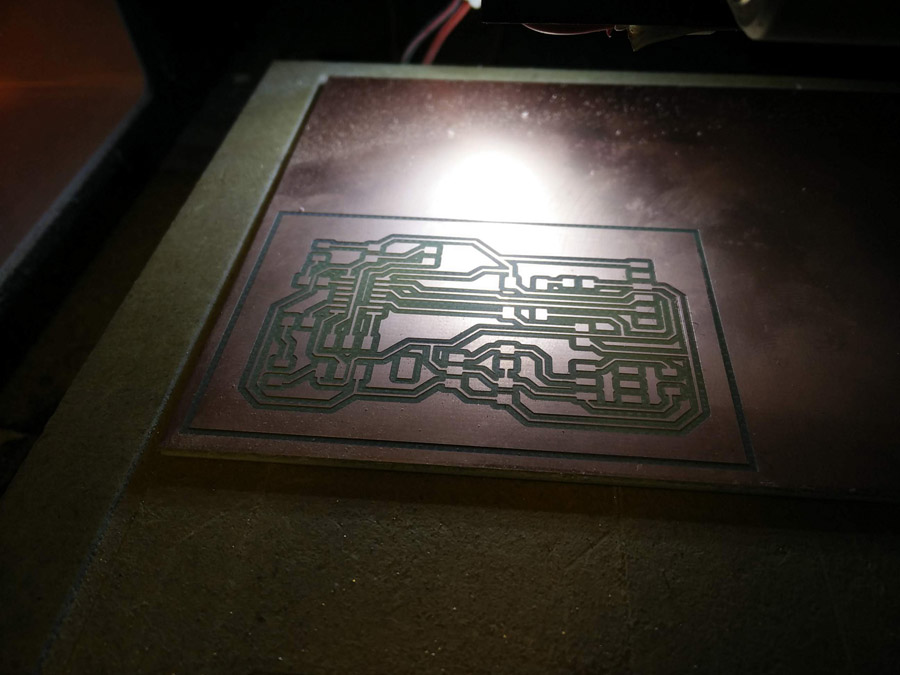
My traces cut from the SRM-20 was successful first time - later ran the second cut file.
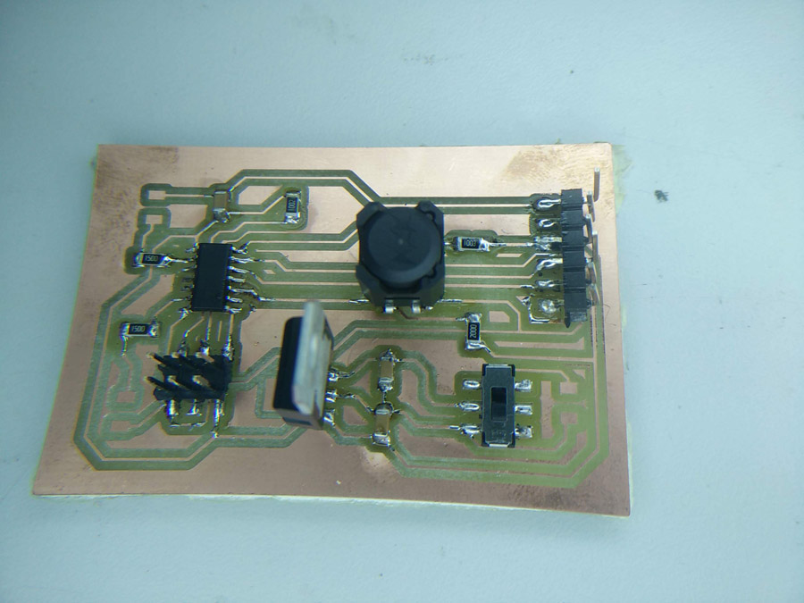
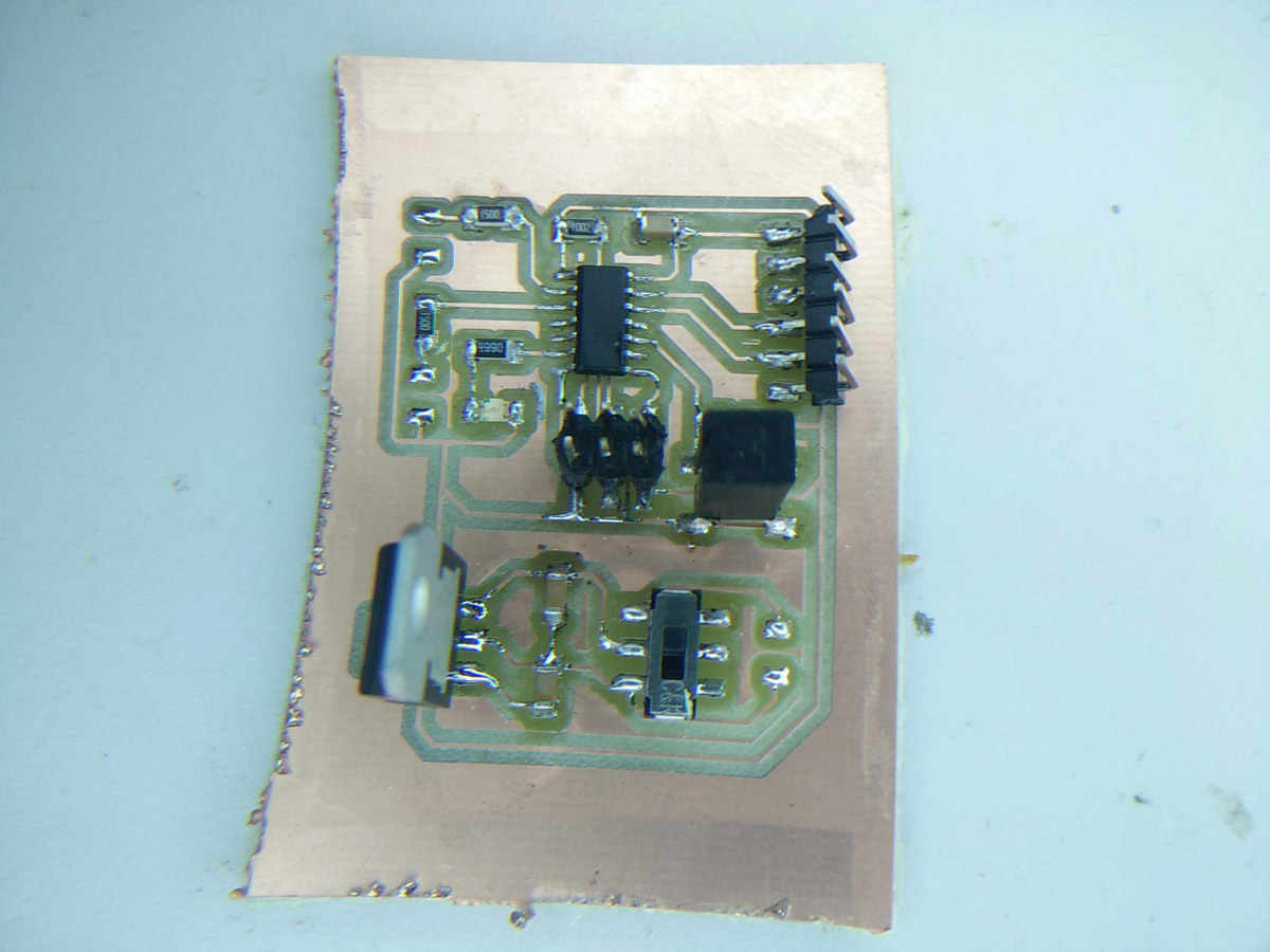
I took care to solder the components carefully, particularly the tilt switch which need to be parallel (flat) to the board. The legs of the regulator had to be clipped short and placed perpendicular to the board. The (battery) switch could be soldered in either direction.
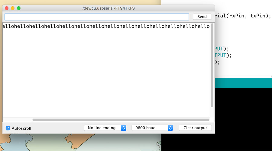
With the my components soldered, I was able to program my board and pick up serial communication. I used the same program serialtest1 (as in Input Devices week) to check the board was transmitting a signal.
While the signal was transmitting, there was no power going through the tilt switch. I used the multimeter extensively to check that 5V was present at each step of the battery routing but clearly, the tilt switch operated differently to how I expected. I had read the datasheet thoroughly, matching the resistance and checking the direction to solder legs. Based on the time constraints, I decided to cut another board and use the tilt switch from my input board, which I knew was working.
Mold & Cast
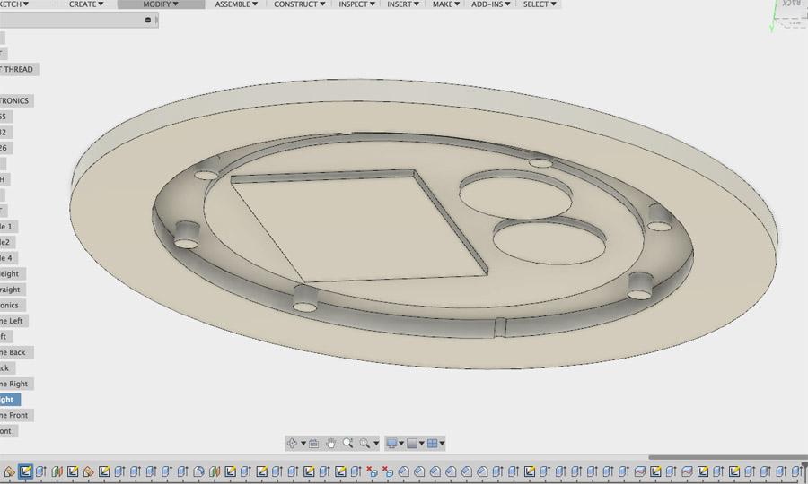
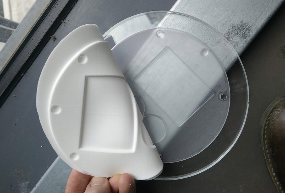
I envisioned the enclosure to hold the electronics as a flat disc made of silicone. It needed to be quite thin, so not to add a lot of additional weight. I worked in Fusion 360 to prepare a negative of the disc I had modelled. I found viewing the piece upside-down helped to visualise how the CNC would cut the piece.
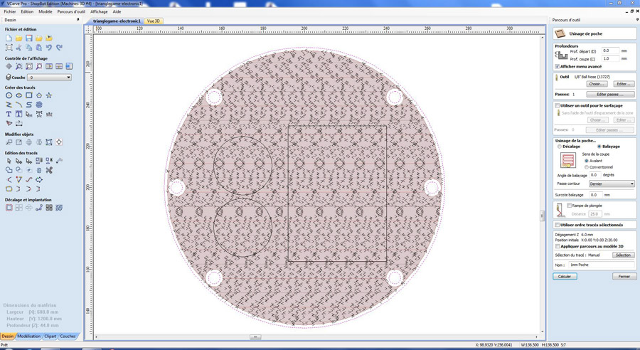
I used V-Carve Pro to prepare two pocket cuts. I worked within the confines of 6mm acrylic – The first cut would go down just 1mm, creating the base for the positive disc. Circular gaps would fit around specially constructed cylinders on the inner rim of the mid section. In hindsight, I could have made this 2mm without adding too much weight.
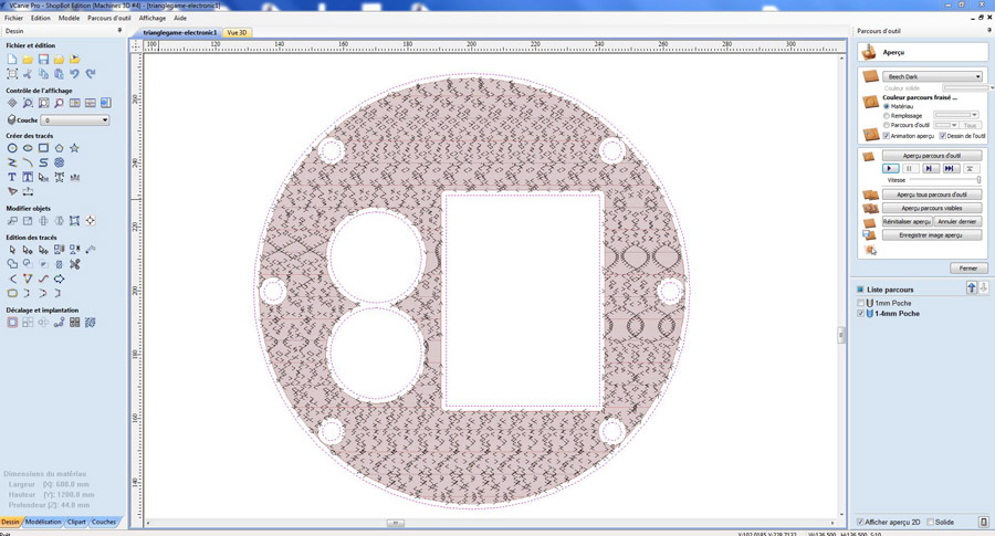
The second cut went down 2mm, housing the batter holders and pcb board (1.8mm thick). A 1/8” ball nose joint was used for both jobs which were run at the same time.
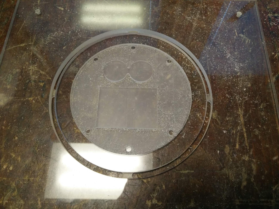
In the end, a piece of 8mm thick transparent acrylic became available. I tested ball nose joint using a small square on a corner of the acrylic. When it cut cleanly, I ran the two jobs using the Shopbot software.
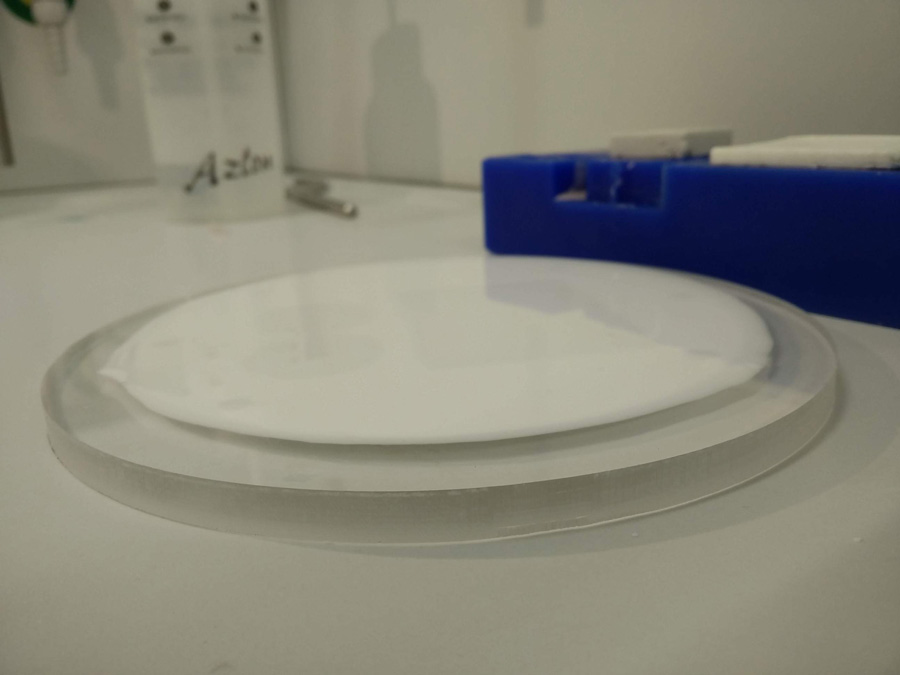
In L'Espace Chimie, I used measured and mixed the silicone as in Molding and Casting week. The cast filled with 68.2ml – 62ml of Part A and 6.2ml of Part B. I then used the air extraction chamber to remove bubbles, running it five times.
After twenty-four hours, a thin mold had been successfully produced.
PCB Board 2
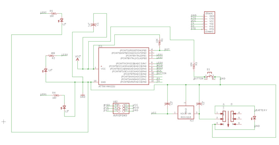
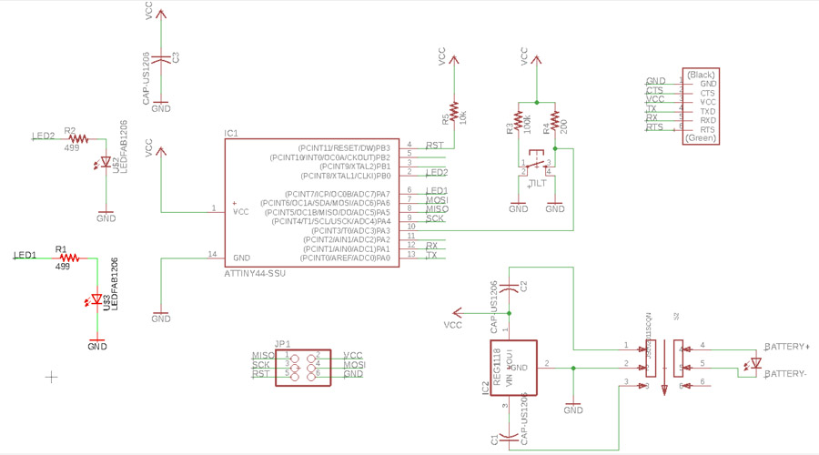
I returned to Eagle to create the second board. This time, I added the following components,
- ATTiny 44 x1
- Arduino Starter Kit Tilt Switch x1
- 5V Regulator x1
- 1Uf Capacitor 25V x3
- Resistors: 10k x2, 150ohm x2 (High Power LEDs), 499ohm x1 (SMD LED)
- 2x3 pin header
- 6 pin FTDI header
- SMD switch (for battery)
- 1206 SMD LED x1 (to test output)
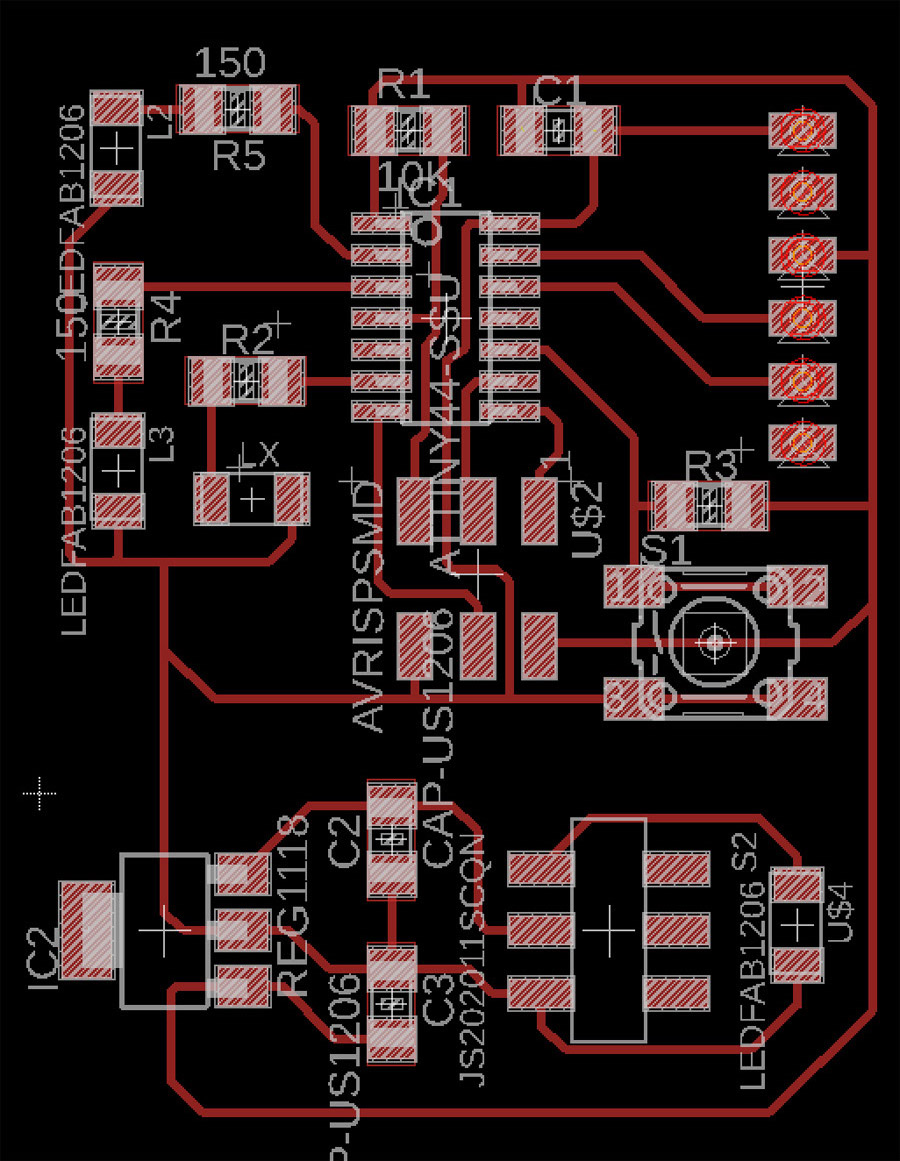
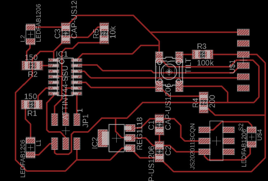
The traces were then routed as before in Board View. Some rearranging of components needed to be done.
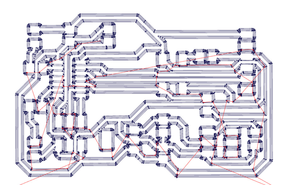
Return to Fabmodules, I prepared the trace and cut files. I then cut the exported .rml file with the SRM-20. The cut out was particularly rough – The tool may be getting old – and I would smooth this off using an electric sanding tool later.
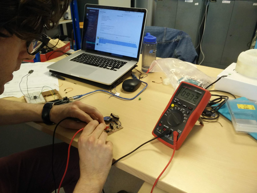
I soldered my components including a similar switch for the battery. Unfortunately, this switch also had an issue – It did not transfer power to the battery (upper) trace when in the 'on' position. I was forced to desolder the switch and connect the traces with a wire. I tested the completed circuit with a multimeter.
With the board complete, I worked on the program in Arduino IDE to match my inputs and outputs. The Tx and Rx pins for communication were matched to the ATTiny44 pins,
#include
#define rxPin 0
#define txPin 1
SoftwareSerial serial(rxPin, txPin);
Integers were then defined for the two high powered LEDs and the tilt switch. I also needed an integer for the sensor output.
int led2_pin = 10;
int led1_pin = 9;
int tiltswitch = 3;
int value_B_sensor = 0;
I then need to define the inputs and outputs in the setup method,
void setup() {

pinMode(rxPin, INPUT);
pinMode(txPin, OUTPUT);
pinMode(led2_pin, OUTPUT);
pinMode(led1_pin, OUTPUT);
pinMode(tiltswitch, INPUT);
serial.begin(9600);

}
In the void loop, I define value_B_sensor as a digital (rather than analogue) sensor on the tilt switch. I also test the serial by outputting the value_B_sensor over serial (serial.printlin). There is also a delay of 500miliseconds
void loop(){

      value_B_sensor = digitalRead(tiltswitch);
      serial.print("the status of the button is: ");
      serial.println(value_B_sensor);
      delay(500);
Staying within the loop method, I add an if-else statement, indicating that if the value_B_sensor is equal to 1 (not 0), blink the LEDS on and off in succession. This corresponds with what I need for the tilt switch: If there if the switch has been tilted (considerably), light the LEDs. Internally, The ball inside the switch drops out of the position and this registers on the circuit.
if (value_B_sensor == 1) {

  digitalWrite(led2_pin, HIGH);
  digitalWrite(led1_pin, HIGH);
  delay(500);
  digitalWrite(led2_pin, LOW);
  digitalWrite(led1_pin, LOW);
  delay(500);

} else {

   //do nothing

}
}
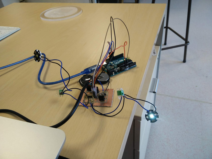
I tested the code on my board, first with the power from the LED and then with batteries soldered. The code successfully lighted the LEDs when turning the tilt switch.
To check the angle of sensitivity, I attached the board to lamp head and rotated it.
3D Printing
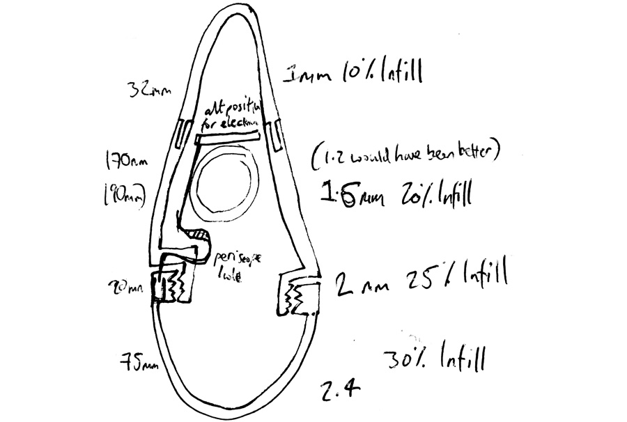
After my test pieces, I decided on the following strategy for printing the different sections. The base would be made of a heavier, thicker material to provide stability and withstand th e most impact (2.4mm wall thickness, 30% infill). This would decrease in the higher sections, leading to the top (1mm, 10% infill). I worked in increments of 0.4mm to match the extruder size, as recommended in the 3D Printing Handbook.
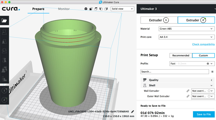
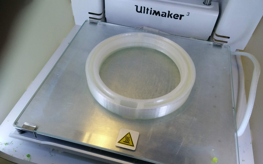
I returned to Fusion to prepare my final 3D prints. The first body to be exported to Cura was the mid section. I rotated mid section so the threads (the most critical part) were off the print bed. This is an area where more damage is likely. The print duration was a whopper 31hours 2mins.
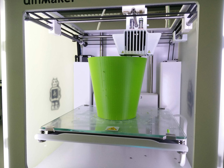
The mid section printed without supports, apart from the small cylinders on the rim. They could have been achieved with angular supports - I will add for the next prototype.
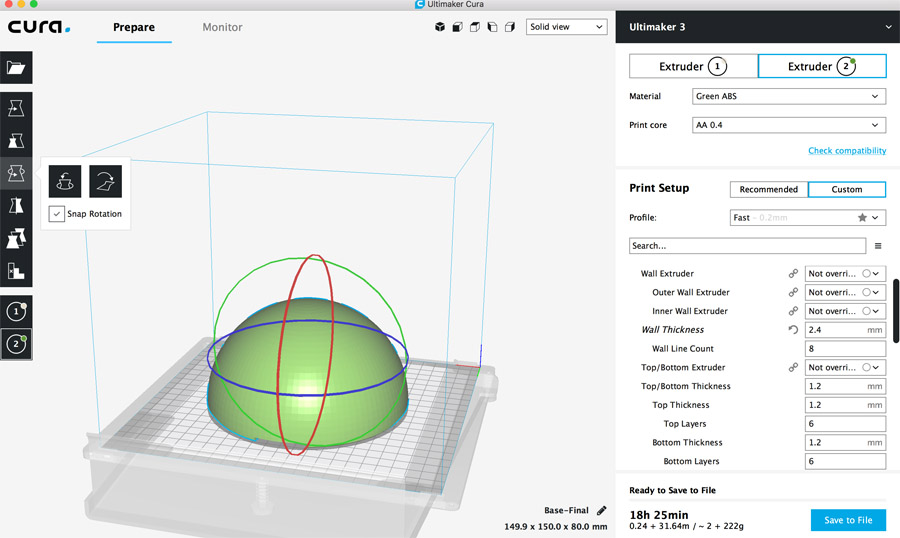
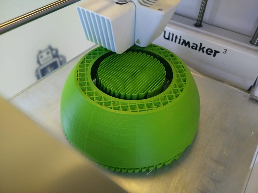
I then prepared the base in Cura, rotating and positioning it at 0 on x/y/z axis.
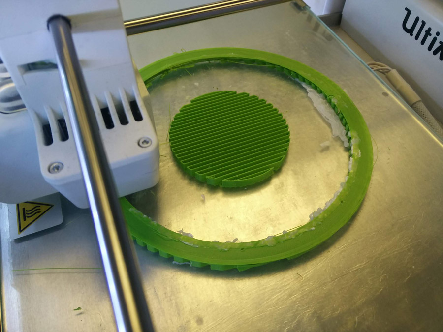
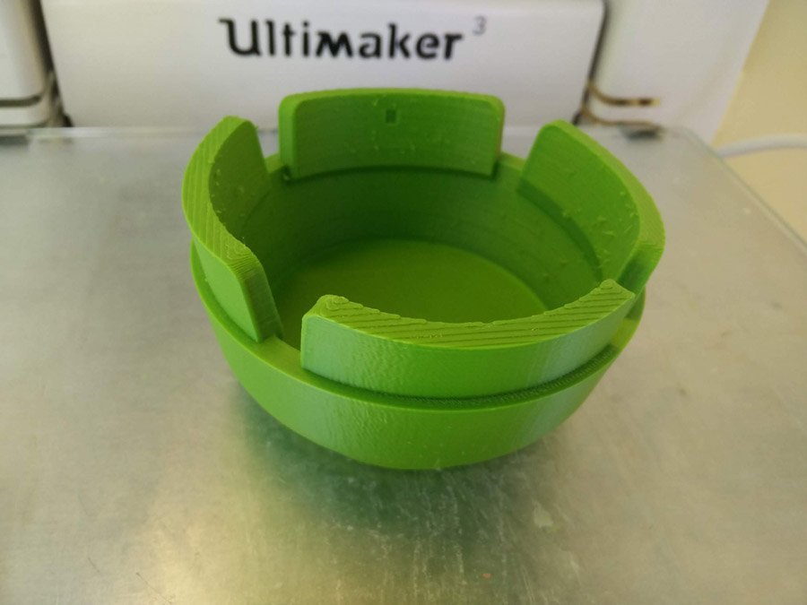
My first base print was without supports. Within minutes, the print had slid from the bed and was turning into spaghetti. I reexported with supports and added a generous amount of pritt-stick to the bed. The second print (seen here) went awry early in the proceeding – Rather than restart and waste material, Jean-Philippe assisted me in using a 3D printing pen to repair the gaps. Most gaps were in the support material, so the main obkect was not compromised. The piece eventually printed successfully.
I then printed the light section containing contre-threads and pockets for the LEDs. Initially I wanted to print the base and light together using the dual head extruder. When this was blocked, I redesigned the parts to be printed separatey for press-fit construction.
Finally, the icing on the cake, the buoy top section. Now only 32mm high, it is not as tall as I had hoped, but was more likely to balance with the counter-weight.
I completed my prototype in week 21.