Output devices
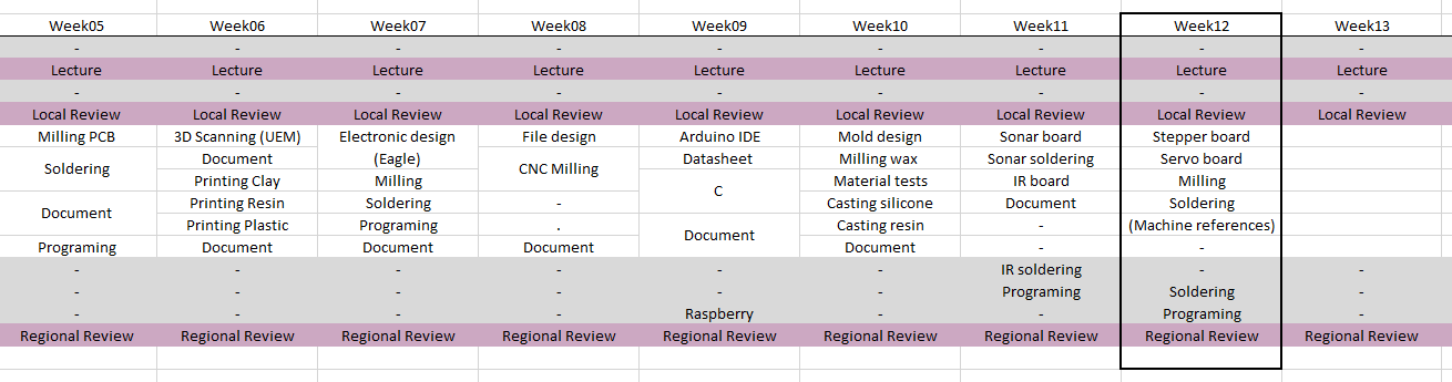
Week 12
Like every week I started the week planning the assignment.
Group assignment. Measuring the power consumption of an output device.
I usually do the group assignments individually as I am a remote student and none of my colleagues are in the fab academy, but in this case, we decided to meet the four of us (Leon remote students) and do some group assignments together.
For this assignment, we decided to measure the power consumption of the PCB that I designed in the Electronic design week.
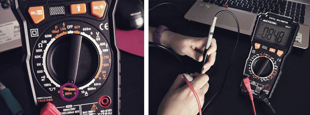
To measure the voltage, we loaded a sketch that makes the LED to turn on/off when you press the button and we supplied the PCB from the computer. Then, using a multimeter, we measured the voltage when the LED was on (4,8 V) and off (0,0 V). We also measured the voltage after the resistor (1,7 V).
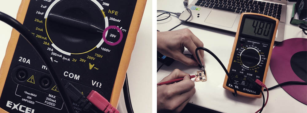
To measure the current, I uploaded a sketch that makes the LED blinks every 3 seconds. Then, using a multimeter, I measured the current when the LED was on (85,0 mA) and off (0,0V). I also measured the current after the resistor (9,6 mA).
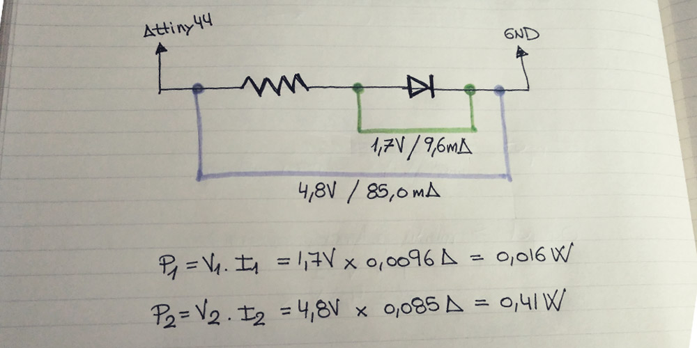
In order to calculate the power consumption in a direct current circuit (DC), we have to use the following formula:
P (power) = V (voltage) * I (current).
Bipolar stepper motor
For this assignment, I wanted to try some different kind of motors that I could use for my final project. My idea is that the motor opens the exterior layer of the lamp allowing to the light to come out.
Additionally, I also thought it would be a good idea to add a BUS connector so I can use this board for the networking and communications week. I took as a reference the Neil's board.
The components that I used for this boards are:
> 1 x ATtiny44
> 1 x 10kΩ resistors
> 3 x 1uF capacitor
> 2 x 10uF capacitor
> 1 x 2x3 pin header (ISP)
> 3 x 2x2 pin header (POWER + BUS + motor connector)
> 2 x Motor driver A4953
> 1 x Regulator 5V 100MA
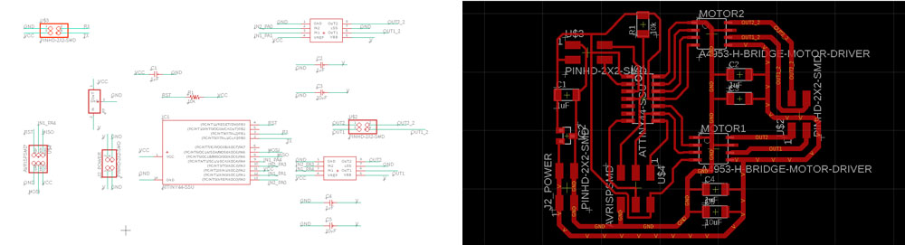
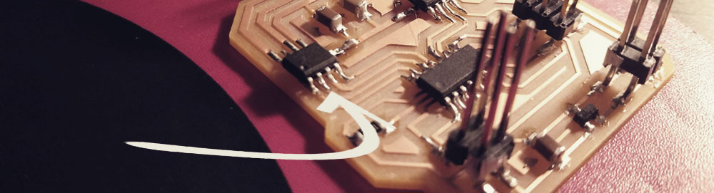
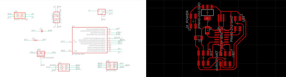
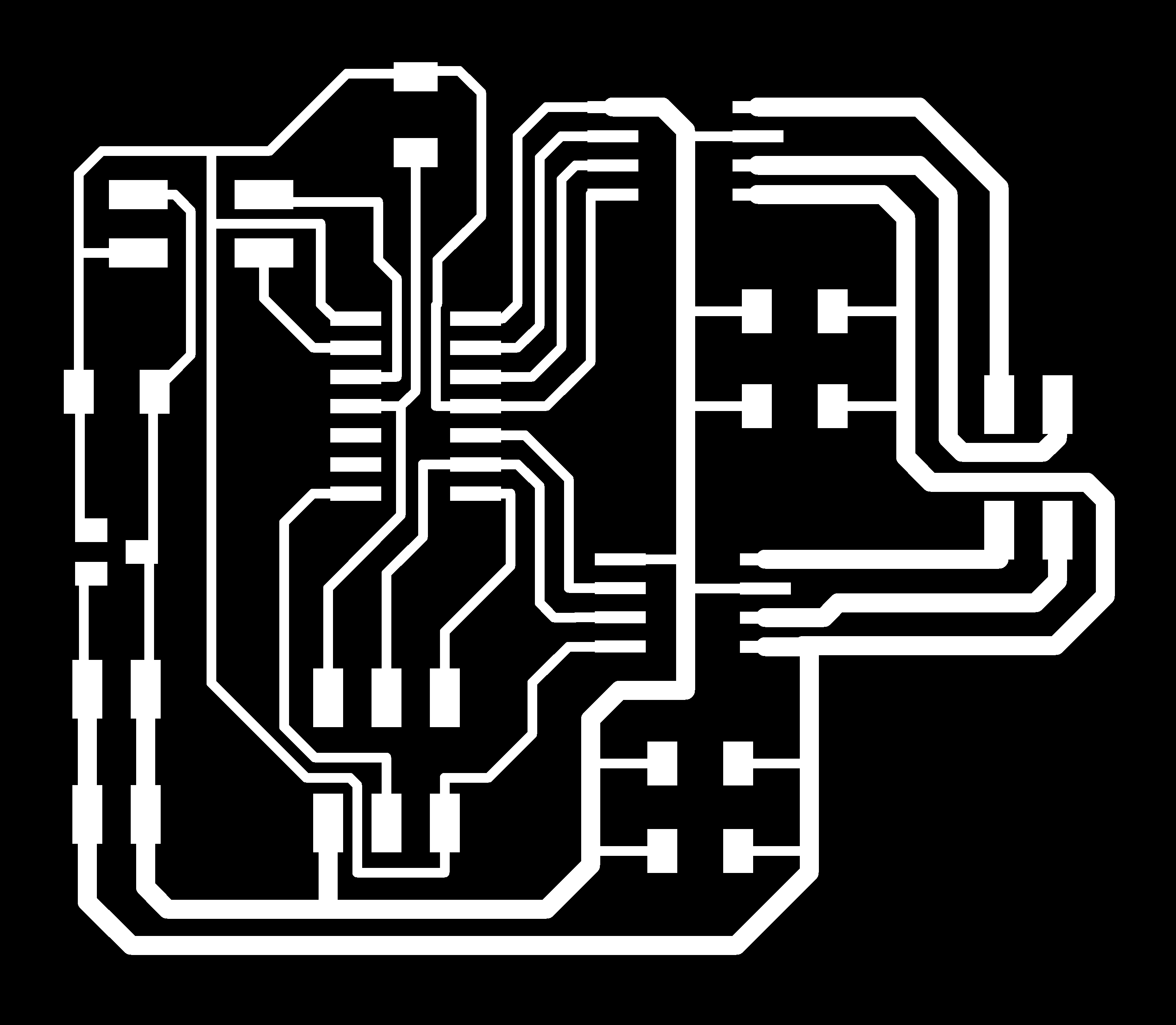
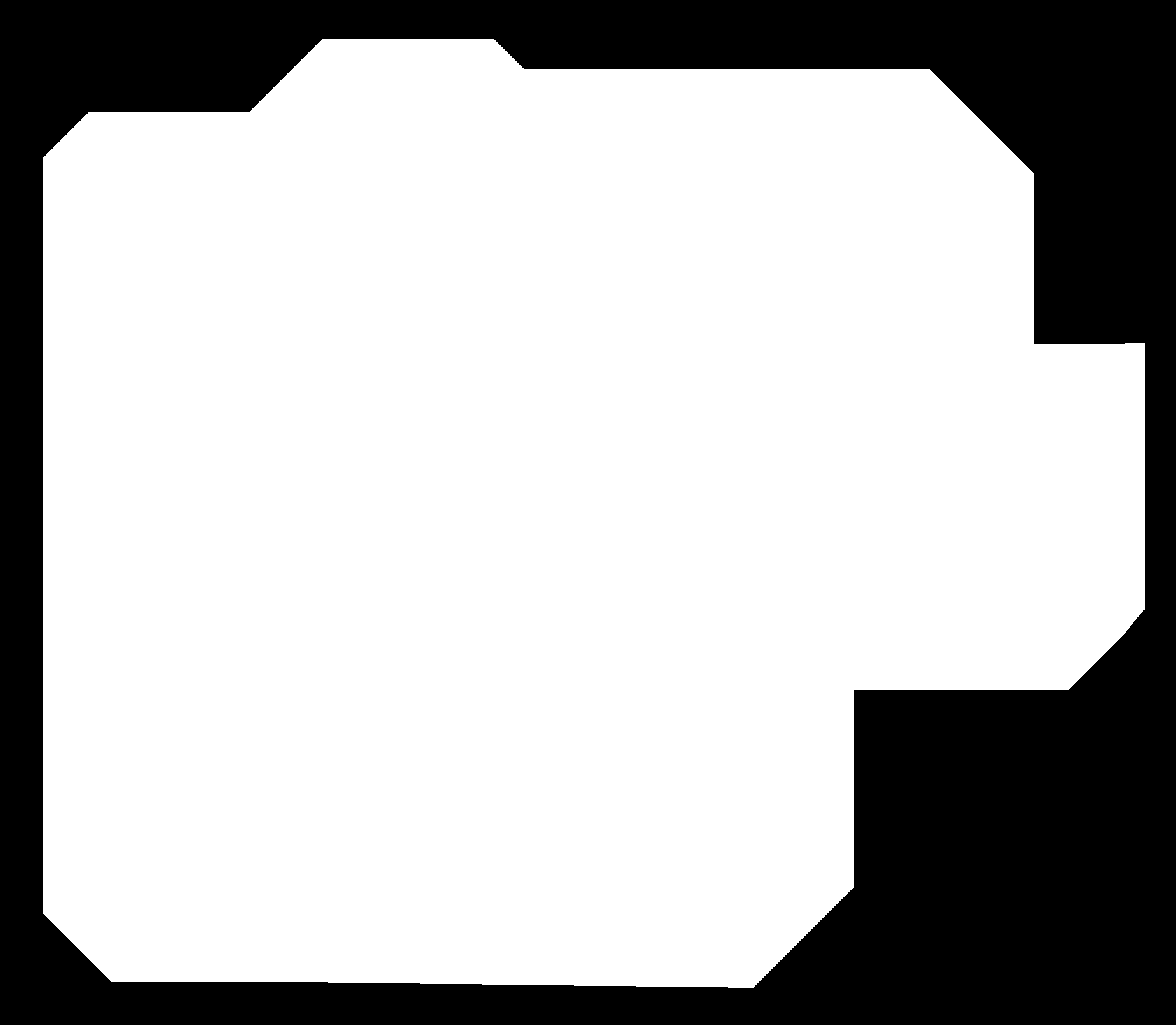
I designed the PCB in Eagle. I created a new schematic, I added all the components and I made all the connections using labels. Then I created a board file from it, I checked the design rules and I arranged all the components and traces. I was very careful with the traces because some of them need to be a bit thicker to support the power, so I used 16ml for the traces that came from the ATtiny44, but 32ml for those which came from the connector for the power.
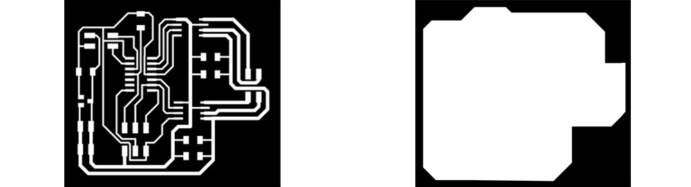
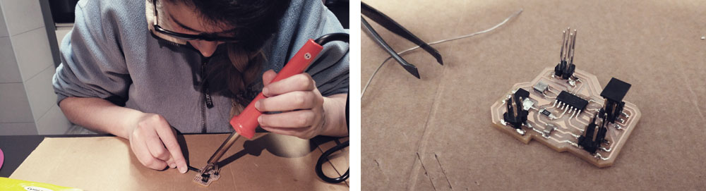
Then I exported the images for the traces into .png, I got the .rml files through Fab Modules and then I milled the PCB. I had to send a few times the file because for some reason the z-sensor wasn't working well, and when I tried to mill the PCB the z distance wasn't the correct one and the cut was to depth. After a couple of attempts, I decided to restart the machine and the computer. After that, the milling part went quite smoothly, without any incident and the board finally came out nicely. Then I soldered all the components and I checked with the multimeer that all conextions were good.
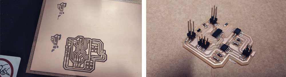
It was a bit difficult to solder the bottom part of the motor drivers. I think I put too much tin and I messed up a bit the board (I hope it works! Fingers crossed!)
Once everything was soldered I made a program in Arduino IDE. Here I had to go to the datasheet of ATtiny44A in order to know the clock that it uses, which is 8MHz. I also had to take a look of the datasheet of my stepper motor, a Nema 8, to know its specifications. Then I had to convert de physically pins so Arduino could recognize in which pins I connected the motor. For the serial output part, I used the SoftwareSerial Library, and I also included the Steeper Library to control de motor.
But, for some reason, I am not able to make it work. The motor makes a very weird and sharp noise while uploading the sketch and then it doesn't complete the movement. Here you can see some videos of how the motor works (or how it doesn't work properly).
In this one you can hear the noise and how the red LED of the FabISP blinks while the motor tries to rotate...
In this one, I am sending a "step by step" movement code...
And finally, in this one, I am sending a "completed revolution" one, and the motor starts good, but then in some point, it gets crazy...
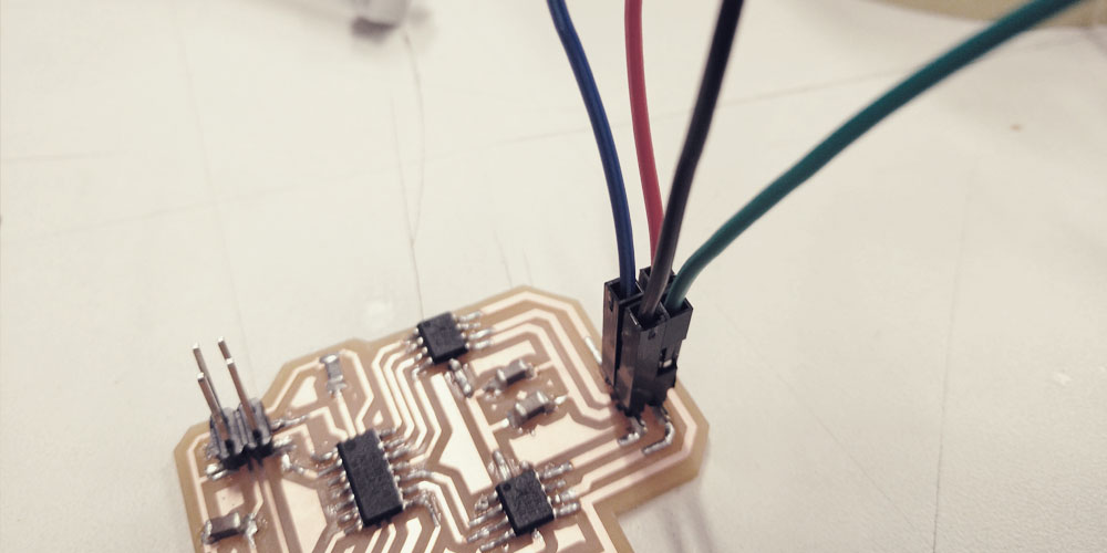
I was checking my schematic comparing it with the Neil's board, Szilárd A. Kados assignment and Marta Verde assignment and everything seems to be fine.... The continuity is good.... The pins' number is well referenced.... I also checked the position of the motor's cables and according to the datasheet and the assignments of Szilár and Marta, they are right connected: black-green / blue-red...
The last thing that I could try was to desolder the motor drivers, as it was very complicated for me to solder the base of the component... maybe I didn't solder them well (I had no way to check the continuity down there) and perhaps that was the problem...
But before doing that I talked with my instructor about my problems and she suggested to change the battery (maybe it was damaged). I was using a 9V battery (the motor driver should be able to works between 8V and 40V), I replaced for a new one, but nothing changed. Then we were discussing how the motor driver works and why it needs to has a pad in the base. According to the datasheet, the exposed pad in the bottom of the motor driver serves both as GND and as a thermal dissipator, so I checked if the components and the traces get hot but no, everything was good in that aspect...
So I was ready to desolder the motor drivers when while checking for umpteenth time the continuity and voltage, I realized that one pad of one of the motor drivers had a weird tiny ball of tin. I barely touched the ball and the ball came off. I had a "soldadura fria" (we say in Spanish (cold welding??)!!! I didn't solder well that part and when I checked with the multimeter I had continuity but the fact was that the pad of the component wasn't connected to the PCB trace!!! So I soldered it again and from that moment on everything started working properly!!!
Finally working!!
Servo motor
I thought it would be a good idea to see how a servo motor works, since I may use it un my final project because I need to move the motor no more than 90º.
I took as a reference Neil's board. but I also added a BUS connector so I can use this board for the networking and communications week.
The components that I used for this boards are:
> 1 x ATtiny44
> 1 x 10kΩ resistors
> 1 x 10uF capacitor
> 2 x 2x3 pin header (ISP + motor connector)
> 2 x 2x2 pin header (POWER + BUS)
> 1 x XTAL 20MHz
> 1 x Regulator 5V 1A ZLDO1117
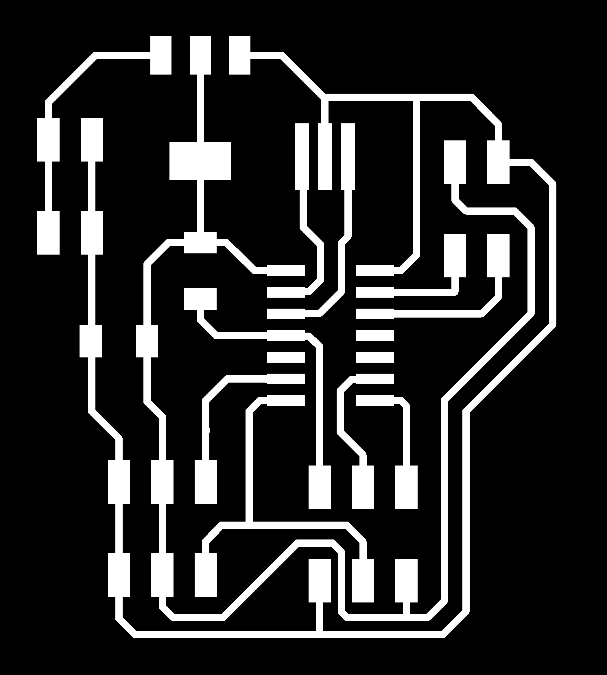
I designed the PCB in Eagle. I created a new schematic, I added all the components and I made all the connections using labels. Then I created a board file from it, I checked the design rules and I arranged all the components and traces.
Then I exported the images for the traces into .png, I got the .rml files through Fab Modules and then I milled the PCB. This time I had some burrs in some paths. I just removed them rubbing with the finger, but I think that the end-mill that I used is overused so I will take a new one next time. Apart from that, the milling process went quite smoothly, without any incident.

Once everything was soldered I made a program in Arduino IDE following this tutorial of Luis Llamas. In this case I am using a external clock of 20MHz. I had to convert de physically pins so Arduino could recognize in which pins I connected the motor. For the serial output part, I used the SoftwareSerial Library, and I also included the Servo Library to control de motor.
When I verified the sketch this error came up. It seems that the Attiny44 has no memory enough to support both servo and software serial library at the same time, so to send up the file I had to erase the software serial part of the code.
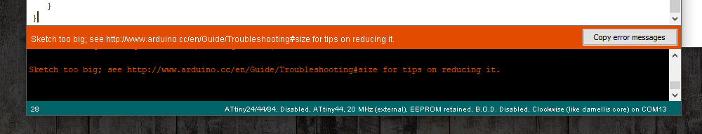
If for the following weeks I want to use both libraries in the same sketch, I will have to change the Attiny44 for another microcontroller with more memory like an ATmega328p.
After that, I worked with the code without problems. I tried with three different brands of servos to know which one works better (I think I prefer the black one, the SM-S2309S, it looks stronger, although I would like to try with one full metal, an MG90S or MG996R). But I realized that, in all of them, if you move the servo very slowly, you can notice how the servo does weird movements: suddenly the movement recedes, it makes like a small jump and then continues running. And I don't know why... (in the video: sec.10, sec. 19 and sec.28)
Since for my project I only need to move from one side to another with a maximum angle of 140-160º, a servo motor is a good option for me and it seems easy to control.
Relay module + LED bulb
I am adding this part of the assignment in week 18 while developing the second prototype of the final project.
To control the on and off of the bulb, I need to incorporate a relay. A relay allows you to manage big voltages with a microcontroller that works with a low voltage. In my case, the LED bulb that I am planning to used works between 12 and 24V. In order to understood better how a relay works I took as a reference this article of Luis Llamas.
To control de device I used the FabKit that I made for the first prototype of the final project. Then I connected the VCC of the bulb to two batteries of 12V (working in series) and the ground to the C and NO inputs of the relay in such a way that, if the system is not working (if the microcontroller is not running), there is no continuity (if you connect the cords to C and NC then you will have continuity, so if you have a bulb connected to a battery and a relay, as in my case, the bulb will be on even if the system is not working at all). I also connected the outputs of the relay (GND, VCC and digital signal) to the FabKit.
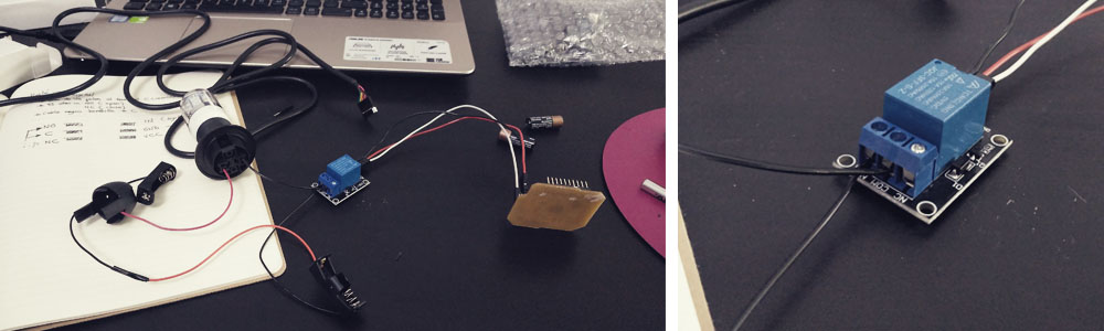
Then I used a very simple loop code that turns on the light for 5 seconds and turn it off for other 5 seconds. An it worked!!
Files
Find below the files that I made for this assignment. Please do not hesitate to download it!! I hope you enjoy it!!
Bipolar steeper motor - traces - .png
Bipolar steeper motor - outline - .png
Bipolar steeper motor - Eagle schematic + board
Bipolar steeper motor - Arduino - .ino
Servo motor - traces - .png
Servo motor - outline - .png
Servo motor - Eagle schematic + board
Servo motor - Arduino - .ino
Relay - Arduino - .ino