Fifth assignment
6 February 2019
Part I
Characterize specifications for the PCB production process
Part II
Make an in-circuit programmer
Part II
For this part I used the hello.ISP.44.res.traces.png for the traces and the hello.ISP.44.res.interior.png for the outline.
Then I used Brian's model for the FabTinyISP traces and for the FabTinyISP outline
Make an in-circuit programmer
PCB design


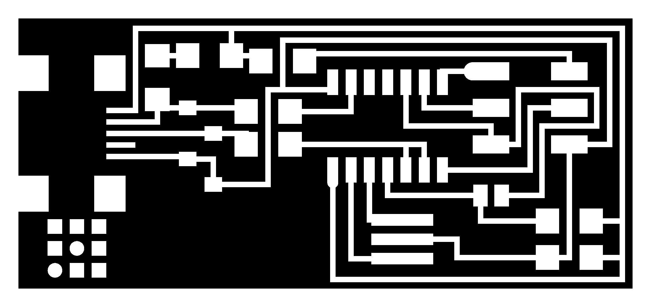

This are the four png archives that I'm gonna be using to mill my boards.
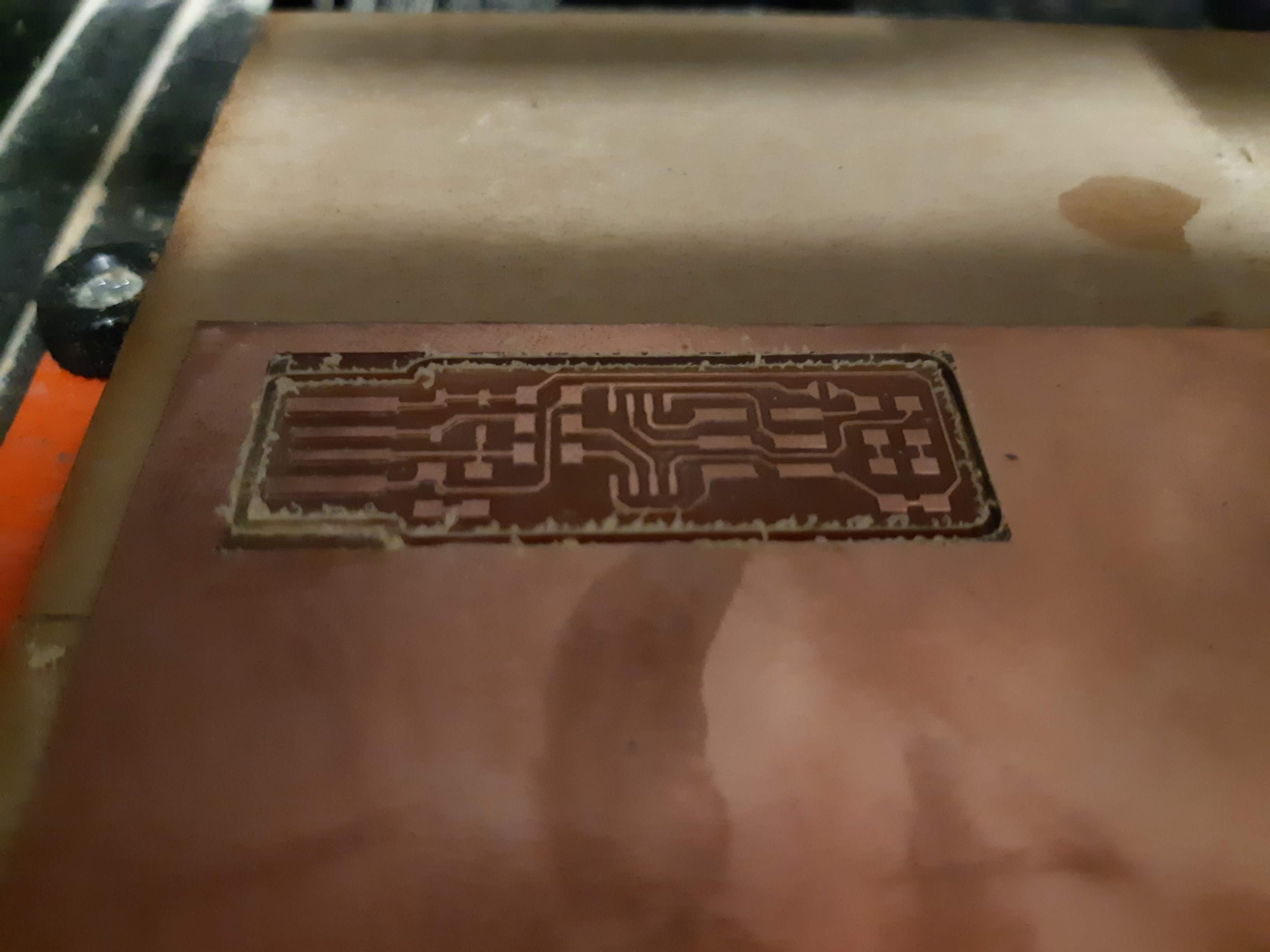
Milling the ISP 44
traces
I was excited to try different things and making this as many times as I could so I tried using a different end mill, a 0.6 mm one.

I used the fabmodules as before in the group part, but when I tried to proceed the software showed a problem

After a few times trying I finally got rid of that error by setting a zhome value.
These are the parameters you should pay more atention to:
speed: 3 mm/s
zhome: 60.5 mm
cut depth: 0.3 mm
tool diameter: 0.4 mm
number of offsets: 1

It finally worked!.


outline
We need now to change the tool from the 1/64 to 1/32 end mill.

As we are changing the tool manually we need to set the new 0 for the z axis again.


Milling the FabTinyISP
Here I just repeated the steps I followed before.
I generated the archives for the traces and for the outline.


Then, after setting a new 0 for x,y and z, I just ran the cut.

After cleaning and sanding it carefully..
Magic!

Soldering process
Using the soldering iron
I have used before the soldering iron but just to re attach some cables, I had never soldered such a tiny piece.

I was having troubles until my classmates gave me the flux.
Flux is an additive used for welding. It allows the heat produced by the welder to concentrate in the area that we are trying to heat. It also makes welding clean of dirt making the union of the pad, component and tin cleaner and more resistant.

After this if seemed really easy, although the technique you see below is not correct.

I know this doesn't look good but at least there's improvement.

I practiced a couple of times more after this, I didn't want to ruin the components.
Placing the components
These are the components we need
1 ATtiny45 or ATtiny85
2 1kΩ resistors
2 499Ω resistors
2 49Ω resistors
2 3.3v zener diodes
1 red LED
1 green LED
1 100nF capacitor
1 2x3 pin header
You can find the diagram of how to put the components here. It is important to check the orientation for each component, otherwise it wont work.
I had a lot of trouble for this part. I found it really hard, but worth it. I really enjoyed this assignment and regret not having a good picture.

After almost two hours, I finished and it worked!

Programing process
Programming the ATtiny45
This part of the assignment is pretty simple. You can always check the tutorial from Fab Academy - Tutorials.
Two tips for this part
It is recommended to use a USB extension cable to avoid damaging the USB ports.
Check the position of PIn 1 from your ISP header, the connector has an specific orientation and you can verify it by check where pin 1 is.
I connect my board to this device

Working from Ubuntu in a computer in my lab, so I just skip first (software installation) and second (get and build the firmware) steps and proceeded to edit the Makefile by changing the programmers name. In this case I am using the avrisp2 (the small translucent blue programmer).

First command: sudo make flash

As it worked correctly I ran the second command sudo make fuses.

If the first command worked but the second one didn't there is probably an intermittent connection.
For me both worked just fine, so I disconnect everything and just connected the USB port to check it's functionality.
problem
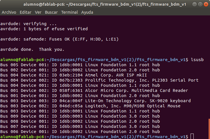
Finally I ran the lsusb command. My device should have appeared on the list but it didn't.
I ran a sudo make clean and repeated the previous steps.
I checked again with lsusb, but still it didn't work.

solution
I finally checked with the multimeter what was going on.
It turned out that the third trace for the USB port wasn't working correctly.
After fixing this, my device finally appeared on the list!


|
What was achieved?
I understood the process of milling a board, the different tools and diferent settings.
I've shown the process that worked for me and also a little problem I had and how I fixed it.
I learned how to solder and to check with the multimeter the connections.
I learned how the micro-controller works for programing and communication with the problem I had.
What was not achieved?
I have a lot to learn about different methods of programming a board yet.
I soldered my board quite nice for a beginner, but I still need a lot of practice. Each component have a different configuration so they cannot be soldered exactly the same way as others.
Part I
Characterize specification for th PCB production process
Part II
Make an in-circuit programmer