Wk14. Networking and Communications
Individual assignment: design and build a wired &/or wireless network connecting at least two processors.
Group assignment: send a message between two projects
Physical Computing
The goal of this week is to create a wired or wireless network connecting at least two processors. But first some theory:
Parallelism
Networks are used for many reasons. The most obvious one is location: getting devices to speak to each other across distances. But equally important is the concept of parallelism. This is where a complex system is broken down into individual tasks that are managed by separate processors, effectively creating a multi-core architecture.
Control
Take for example, a big machine than needs to control various axes, a user interface, and an end effector. Rather than having a time-sharing operating system on a big processor, you can split the various tasks between multiple small processors running parallel to each other. This sort of architecture can greatly enhance control and flexibility.
Modularity
Another benefit of this is modularity. If each task is controlled by separate processors, this helps us develop and debug each module individually before integrating them. Also the machine/device/system may have one part that uses high current, another that is low noise, one at high voltage; which may cause interference between components. So by having a modular network you can avoid interference, and separate the sub-systems accordingly.
Serial Communication
This week I want to focus on the most basic form of communication used to interlink circuits: Serial Communication. Then if I have time I will try and play a bit with 12C and wireless.
Take me home country road
Serial interfaces stream data one bit at a time, kinda like a two-lane country road where traffic is slow (only one car in each direction) but it’s a cheap and steady ride. Parallel interfaces transfer multiple bits at a time often requiring multiple wires, like a superhighway. It’s fast but means more lanes to build using more processor pins.
Serial Comms

Parallel Comms

Asynchronous: who got the time?
The are dozens of serial protocols that have been developed over the years to meet the different needs of embedded systems. These include Universal Serial Bus (USB), SPI, I2C to name a few that Neil mentioned in his lecture.
The most common form of serial is asynchronous serial communication, which means that data is transferred without support of an external clock signal. This allows digital pulses to be sent back and forth between devices at a mutually agreed-upon rate. The sender sends pulses (representing data) at the agreed-upon data rate, and the receiver listens for pulses at that same rate. Simple right? Hmmm…
The important thing to remember is there is no one way to send data serially. The protocol is highly configurable. This makes it critical to make sure that both devices on a serial bus are configured to use the exact same protocols.
In order to communicate, the devices need to agree on a few things:
- The rate at which data is sent and read.
- The voltage levels representing a 1 or a 0 bit.
- The meaning of those voltage levels: is a high voltage 1 and a low voltage 0, or is the signal inverted so that a low voltage is a 1 and high voltage is 0?
A few rules of the road:
-
BAUD RATE: specifies how fast data is sent over a serial line. It’s usually expressed in units of bits-per-second (bps). One of the most standard ones is 9600 bps.
-
SERIAL FRAME: Each block (usually a byte) of data transmitted is actually sent in a packet or frame of bits.
-
DATA CHUNK: The amount of data in each serial packet carries, usually anything between 5-9 bits. Called chunk because size is not specified.
-
SYNCHRONISATION BITS: the start bit and the stop bit(s) that mark the beginning and end of a packet. There’s always only one start bit, but the number of stop bits is configurable to either one or two (though commonly left at one).
-
PARITY BITS: A very simple, low-level way of checking errors by matching odds and evens. This is optional and not widely used as it slows traffic.
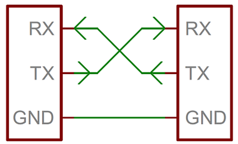
Crossing swords
A Serial bus consists of just two wires: one for sending data and another for receiving. As such, serial devices use two serial pins: the receiver (RX) and the transmitter (TX).
Designing my Serial bus
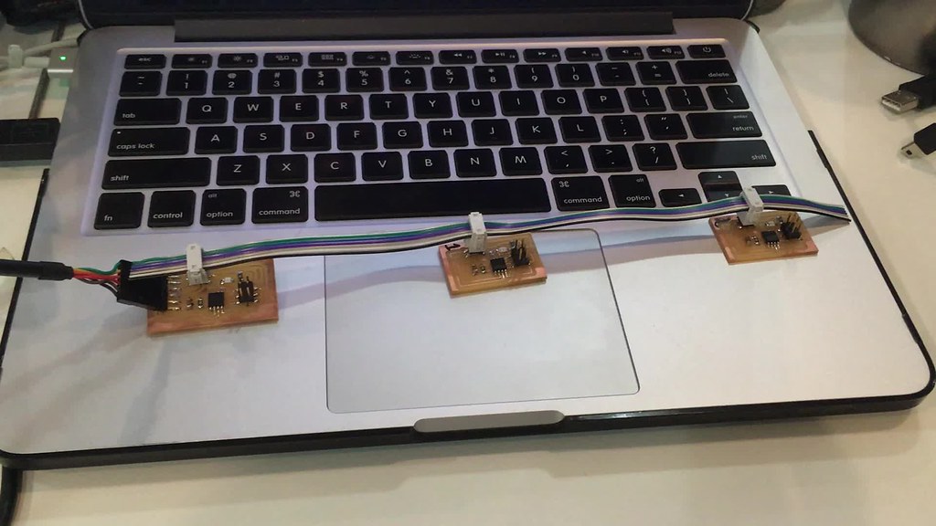
The purpose of Neil’s hello world example is to network several boards together in the form of a serial bus. The bridge board is connected to a computer via a FTDI cable. The two node boards are connected to the bridge board.
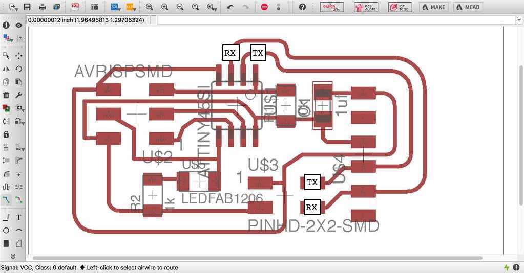
I redesigned Neil’s board layout below, keeping the RX and the TX between the bridge and the node’s are lined up to the same pins (PB3 = TX and PB4 = RX). This was at first confusing, until I understood that it was in Neil’s C code that the inputs and outputs of the pins are switched.
 |
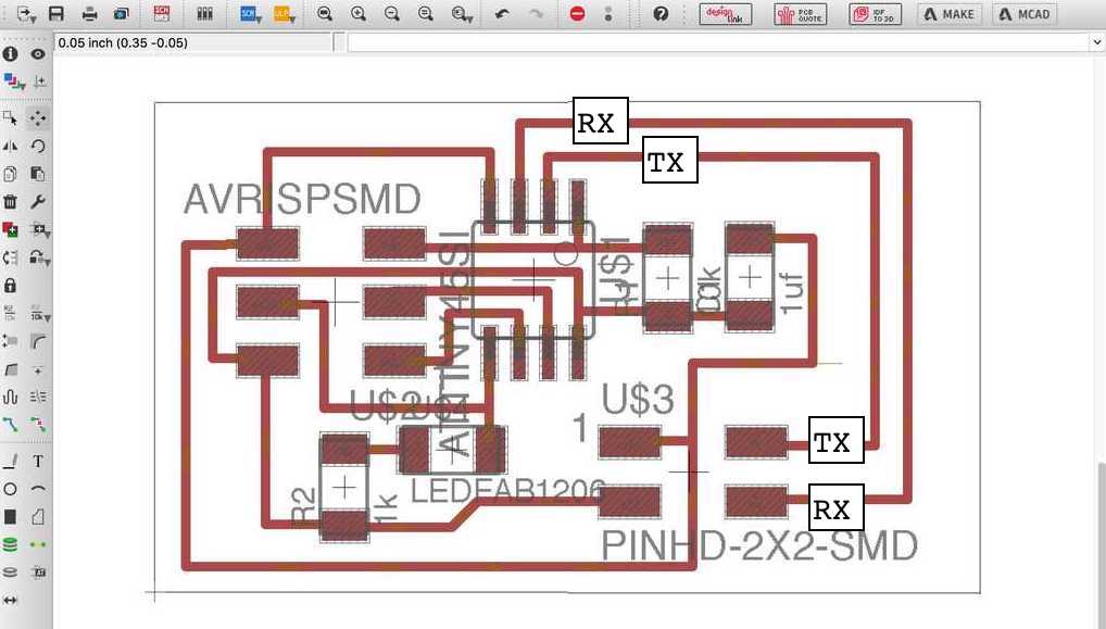 |
Serial bridge and nodes
I didn’t get too adventurous this week on my electronic design. This is because 1. I wanted to keep things simple, and 2. I was anxious to delve into the programming of a serial bus, understand a little more about the actual wiring of a serial bus and work out how to manipulate serial via the software.
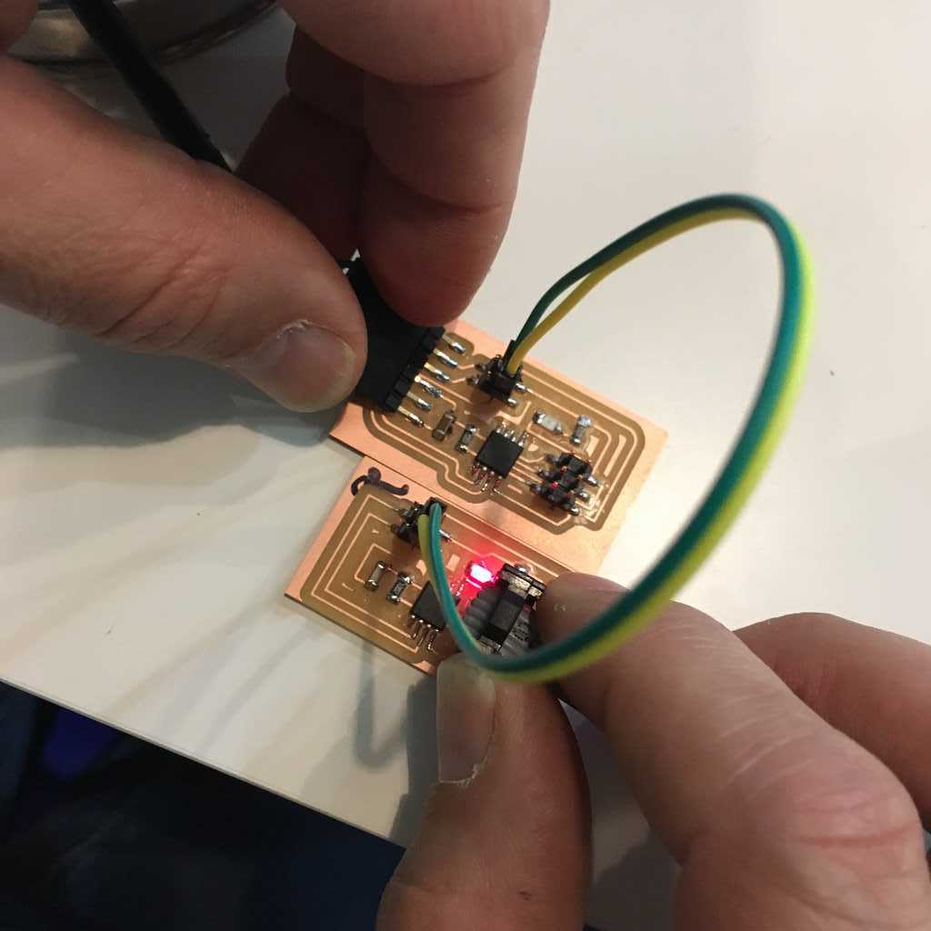
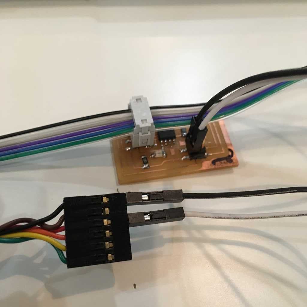
Here I am using the FTDI to provide power and ground while the ribbon cable is communicating via serial.
 |
 |
Programming the boards
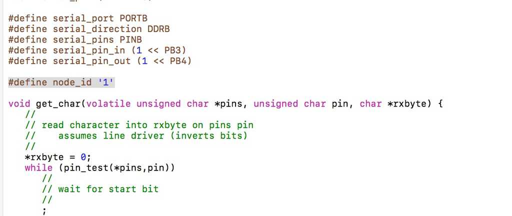
For the programming I worked with Neil’s C code. For each node in your network, I had to modify the hello.bus.45.c C code. The “bridge” board with the FTDI header is also technically a “node”. Each node needs to have a different node ID number (0, 1, 2, 3, etc) In the c code, you need to change the line:
#define node_id '0' and then save the file.
I then connected the the bridge board to my computer via the FTDI cable header and using my FabISP to flash the bridge board as node 0.
sudo make -f hello.bus.45.make program-usbtiny
Next, I modified the C code again and change the node id to 1 and svae the file.
#define node_id '1'
Then I repeated this process for all the boards.
Also it is a good idea to physically write the number of your node on the back of the PCB with a magic marker to not get your nodes confused.
Testing the serial bus
The programming went fine, so now on to testing the serial bus communication. Here I used the Arduino IDE serial monitor, making sure I had it set to 9600 baud rate.
From the get go I seemed at first to have a problem with node 1. But this was very hard to tell because the LED’s flash all 3 in quick succession, before flashing the one called.
Then what I did was change the code, and reprogrammed the board this time using my fabISP that seemed to work fine. What I did was voided the flash at the beginning. This allowed me to see in effect that I had a problem with my node 1:
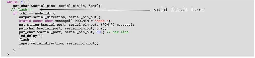
As you can see here below, the LED now only flash to the node that is called.
Some conclusions
After a lot of trouble shooting and back to debugging, I foundout that the problem was with the LED which may have burnt out on my node 1. I will try changing it to see if I can get it to work.
Serial communication is really a quite simple two way communication. With my limited coding skills, I am still trying to figure out how it is that one sets defines which board is transmitting and which board is receiving. I understand the theory, but in coding practice this still escapes me. I will update my findings.
You can download all my design files for week 14 from my Gitlab repository.