Final Project Process
This page is for tracking my progress and process on the Final Project. For the final results, please see Final Project > 04. Final Result.
My Process
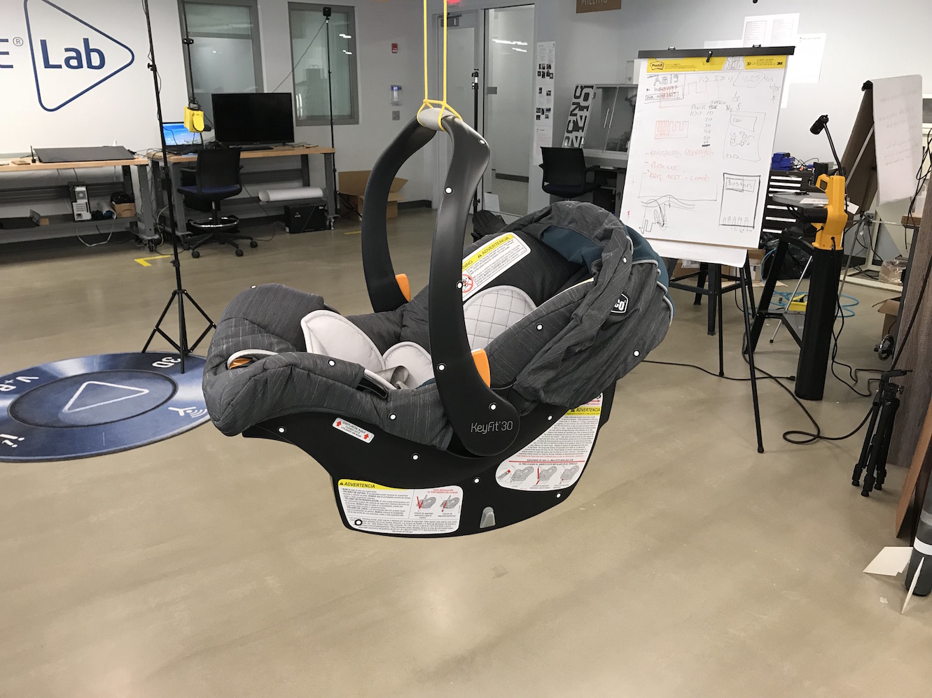
For my Final Project, I would like to make an automatic rocker-base for an infant carseat carrier like this one:
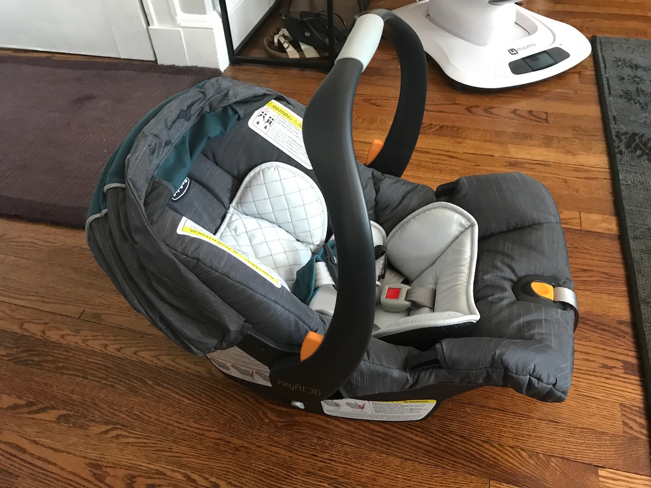
Basically, I would like the machine to be able to rock the seat automatically, without the need for a person or other input to rock the seat.
You can read a background on my process under my Week 16 assignment. This page will track what I've done since then.
Getting Started
I started out by thinking about how to generate the reciprocating, linear motion I wanted to rock the seat. Luciano helped me think through some of that, and we did some basic drawings:
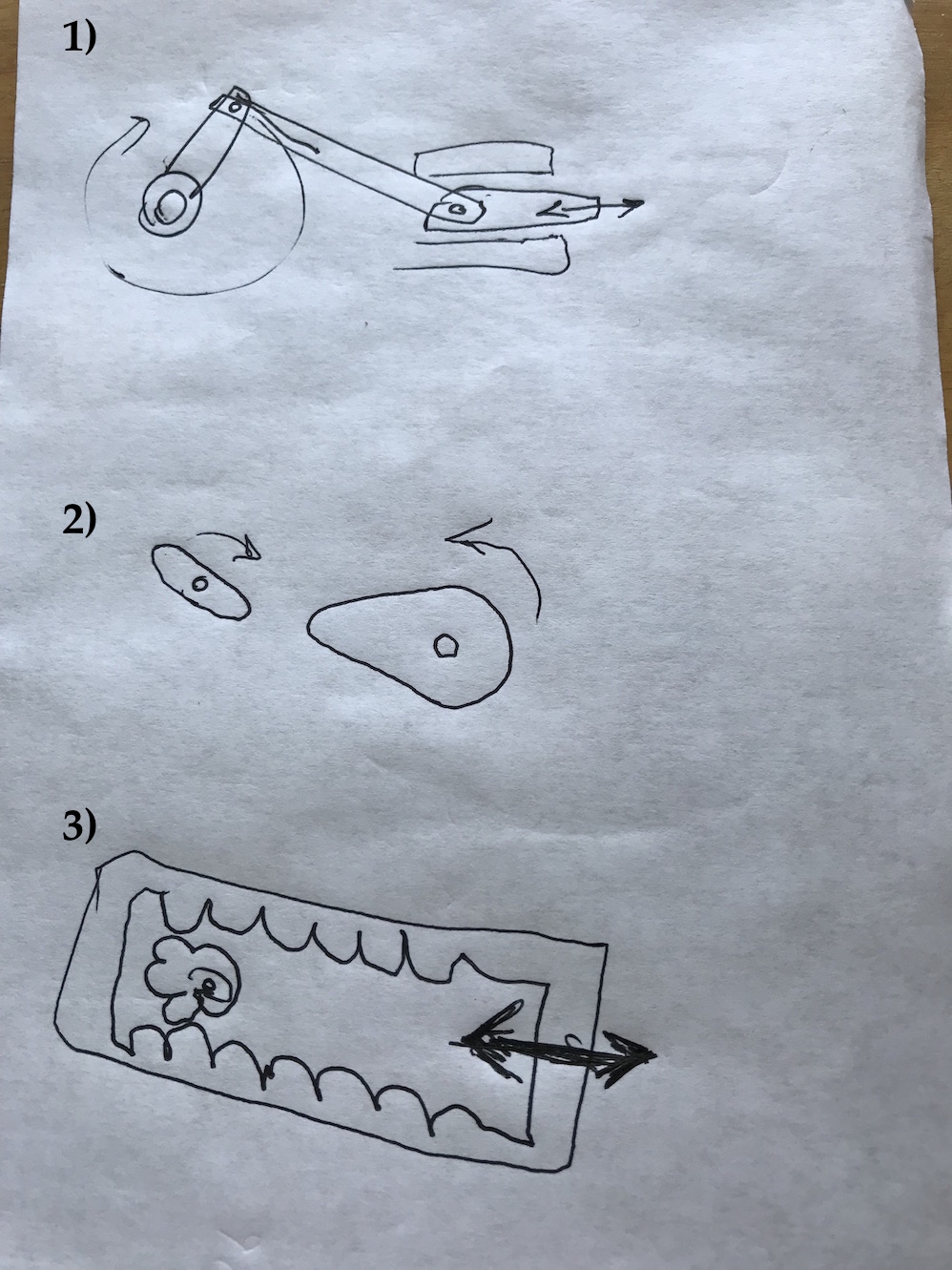
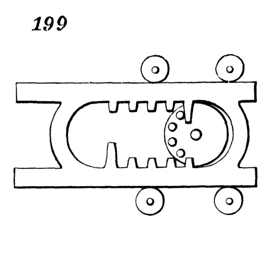
I'm intrigued by the reciprocating rack mechanism. Here's a nice example of one made of wood:
And another great example from 507 Mechanical Movements can be found here:
But I decided I wanted to explore cam mechanisms because they seem much simpler to fabricate and potentially more robust. I did some quick googling, and also a search on 507 Mechanical Movements and found a potentially good option: the heart cam.
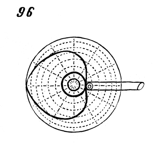
Typically, a heart cam will use a "follower" - a shaft with a friction-reducing mechanism such as a roller bearing - to receive the linear motion and translate it out of the mechanism. In my case, the carrier seat itself will be the follower; the bottom of the rocker is fairly smooth plastic, and I think it will slide easily along a plywood edge grain. In order to use a heart cam to rock my carseat carrier, I would need to calculate the heights of the rocker at full extension (rocked all the way forward) and full "flexion" (rocked all the way back. Relatively straightforward to put the the seat on a flat surface (like the floor) and take some measurements:

These measurements would come in handy when it's time to make the heart-cam and do a CAD model of the base. But first, I needed to do some CAD on the parts I would use, including the motor, and the carrier seat itself.
CAD
I started by emailing Chicco USA, the manufacturer of the carseat to see if they would send me a CAD model or even just a 2d orthographic drawings I could use for reference. I emailed them 2018-05-27, and as of 2018-06-12 I have not heard anything from them. (I'm not terribly surprised at this - the current closed-source, lawsuit-crazy corporate landscape doesn't lend itself to sharing of CAD drawings from large corporations to individual users or hobbyists. It's one reason I strongly prefer an open source model for intellectual property.)
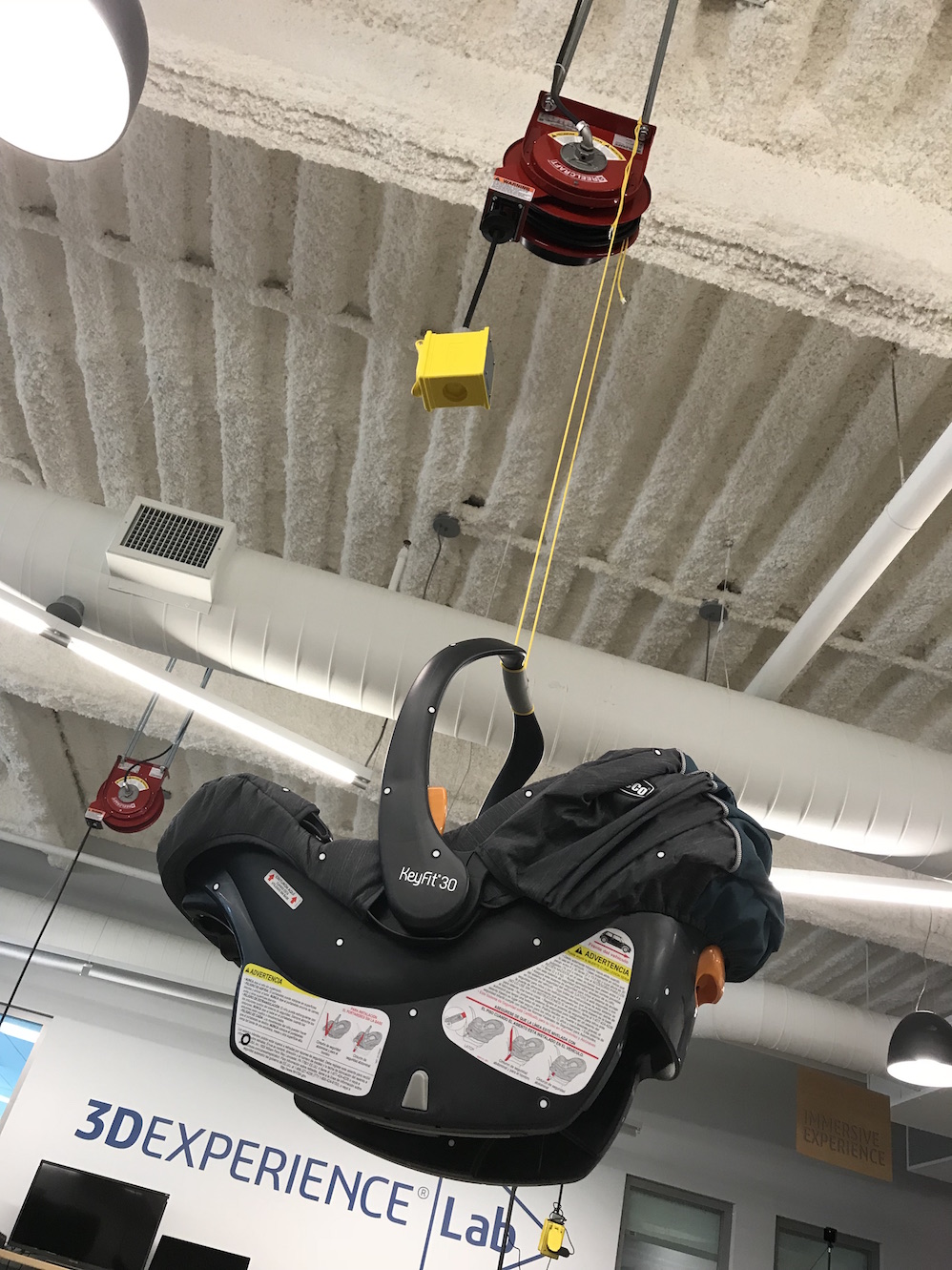
Next I tried to get a 3D scan of the carrier seat. I hung the seat from the ceiling of the Dassault Fab Lab so I could get a good 360° scan, including the bottom and rockers which was the most important part. I covered it in target dots, as per the scanner instructions, callibrated the scanner, and went to town scanning. (See Week 05 for a detailed description of the scanner I used.)
Unfortunately, the scan was not very good quality:
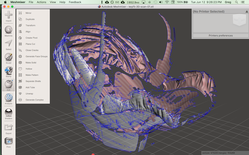
Here's an STL of the scan. You can see how many gaps there are, especially in the crucial geometry of the bottom and rocker sections of the seat.
I was pretty disappointed with the quality of this scan. It's unfortunately not really usable. I think the poor quality is because some of the plastic areas were somewhat glossy and caused problematic reflections of the laser scanning lines. It seems a fairly solid, basic (though complex) shape, and I thought it would be a good candidate for scanning. Maybe if I knew more about the scanner or what settings to manipulate I could get a better scan, but like with so many things here near the end of Fab Academy, I simply had to move on and make do with what I had.
Instead, I did some more rough, but usably accurate measurements by hand and did a CAD model of the bottom of the seat. I started by taking some reference photographs with a ruler included for scale.
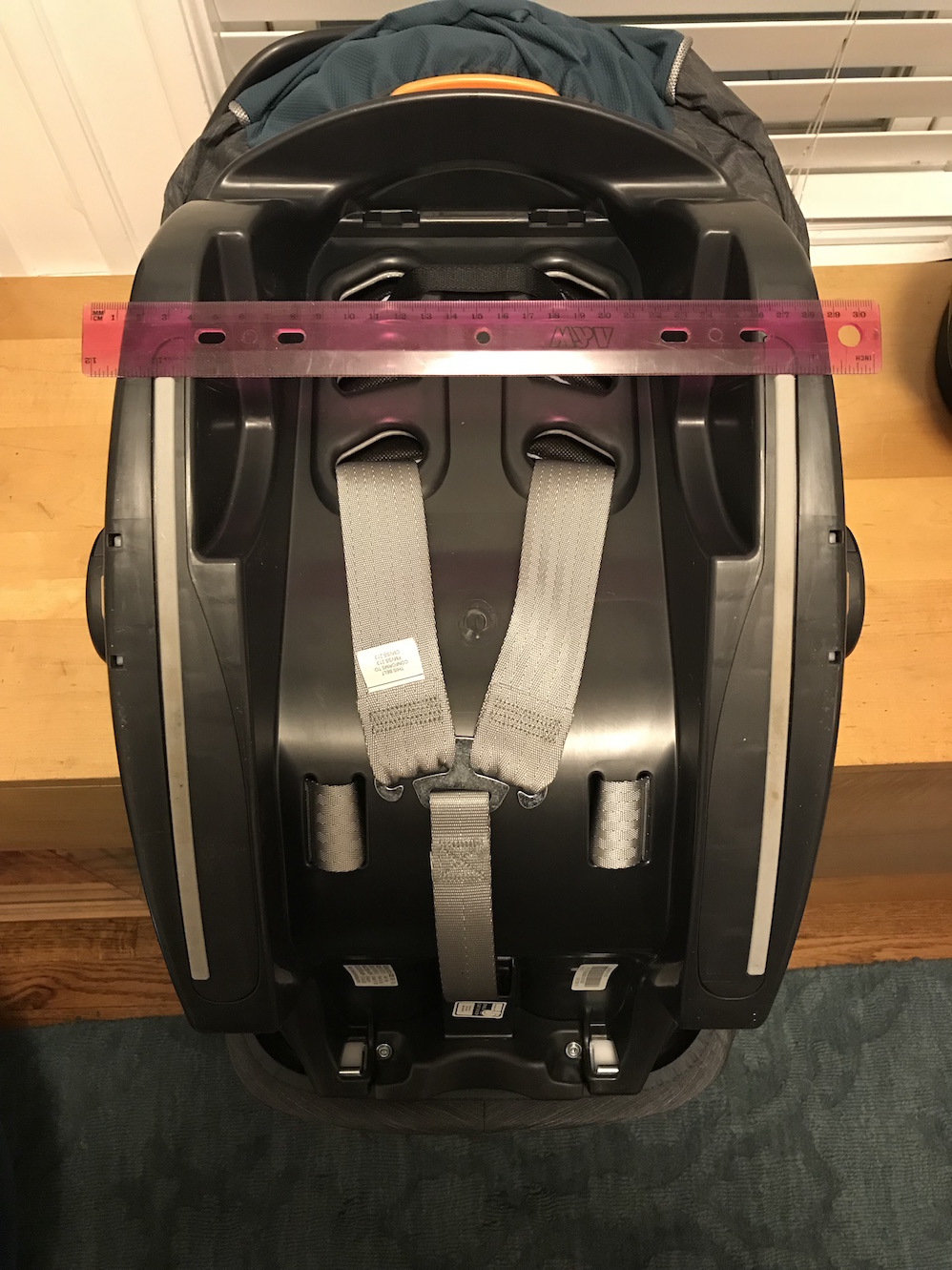
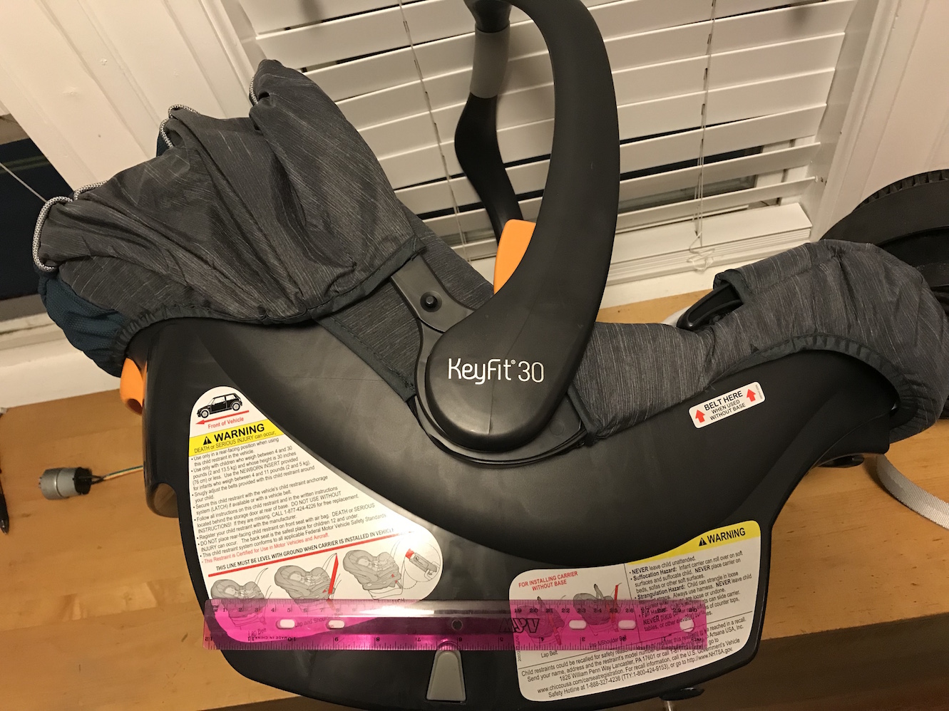
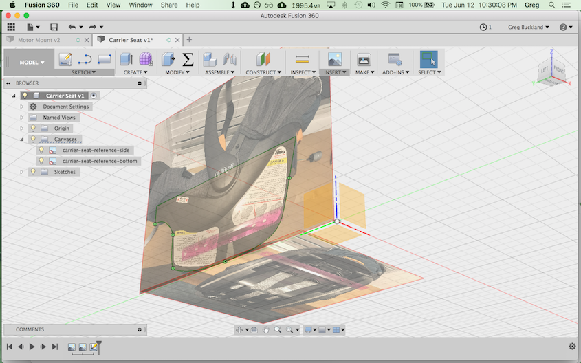
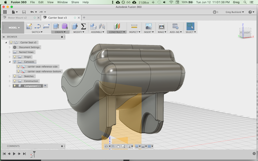
I brought those reference photos into Fusion 360, scaled them appropriately, and began modeling the carseat - focusing on accuracy in the rockers, and not worrying much about the accuracy in the top portions, since they would have little bearing on the mechanics of the rocker.
I also did some quick CAD to represent my geared DC motor so that I could design a motor mount bracket for holding it to the rocker base. I used the motor's datasheet as a reference drawing.
Next up, I used the CAD model of the motor to design a 3d-printable motor mount. Here's an image of the mount design shown with and without the motor inserted:
Motor Mount - Version 01
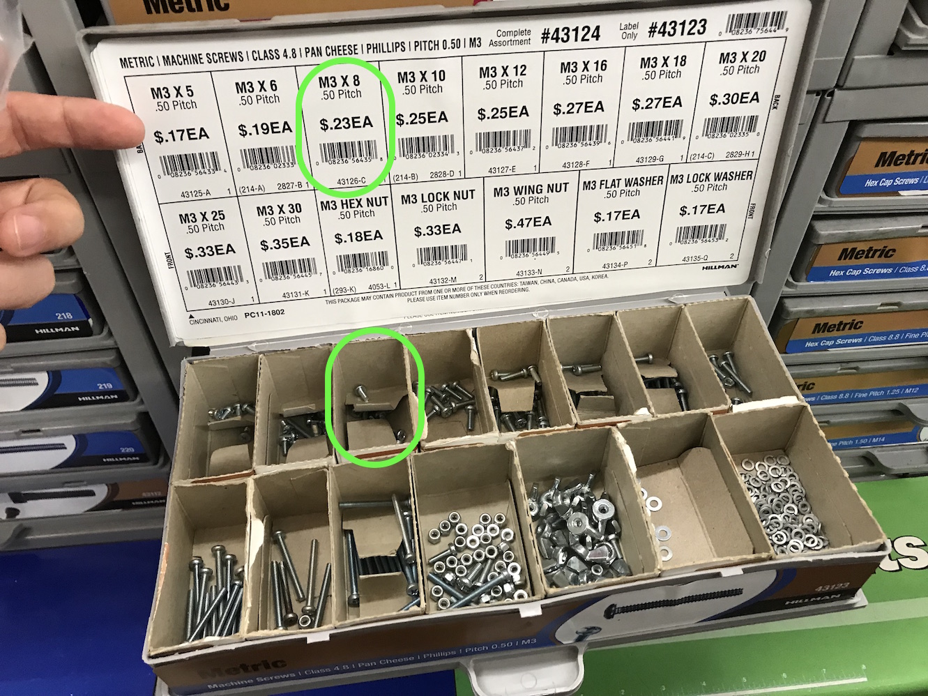
Incidentally, I designed the motor mount to accomodate the screws I purchased at my local ACE hardware store. The mounting screws on the motor are M3 with 0.50 pitch threads. I got 8mm M3 screws to allow for the 4mm thickness of the motor mount face.
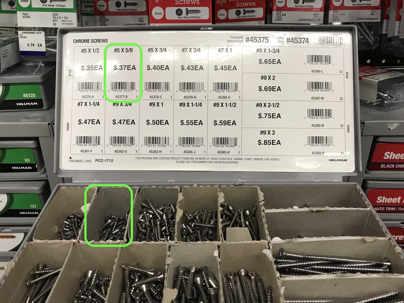
I'm planning to make the rest of the base out of plywood, so I got #5 wood screws at 5/8" (0.625" or 15.9mm). I made the motor mount base thickness 6mm and added a chamfer around the screw holes so the screws would be countersunk, and have plenty of thread to grab into the plywood. If I use 6mm plywood, the thread length should be just right. If I use 3mm plywood, I will have to double it up under the motor mount, which I actually like - it will add some strength to the motor mount area.
Version 01 of the motor mount printed in about 2.5 hours, and it came out OK. But when I put the motor in it, the mounting face snapped off:
I believe I didn't account sufficiently for material shrinkage when I sized the big through hole on the faceplate, so when I squeezed the motor into it, the plate cracked at its weakest spot. But otherwise, the screwholes worked great. In version 02 of the mount, I expanded the diameter of the large through hole by about 5% and added some gussets to the sides for strength. I had another idea as well, which was to add a channel so I could run a ziptie through the mount and around the motor. I could also flip it by 90° and print with the faceplate down, eliminating the weak point between layers at that stress concentration. Lastly, I wanted to try to print it with carbon reinforced Onyx filament for even more strength. These changes would make it "bomb proof" - if maybe a little overbuilt. But better overbuilt than underbuilt, I say. Here's version 02 of the motor mount:
Motor Mount - Version 02
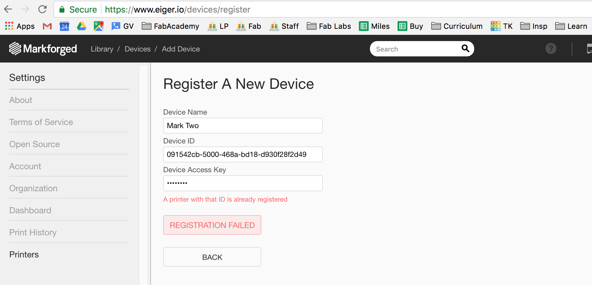
I tried to do the print with our Markforged Mark Two printer using the Onyx carbon-fiber reinforced print material, but alas, Markforged is yet another tight-fisted, IP-crazy corporation, and I couldn't get the printer to work. The computer in the lab that has the (propietary) slicer software installed is down, and I'm not allowed to register the printer on a new device. That is bull**** and it's why, once again, I strongly prefer an Open Source IP regime. Ugh.
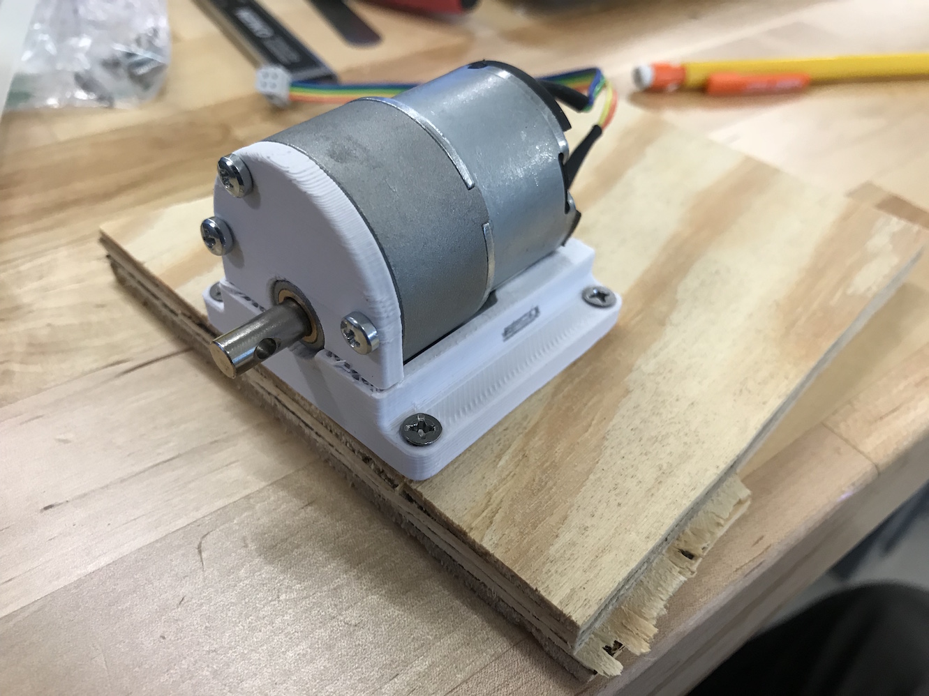
Sigh. Ok, I went ahead and printed Version 02 on the Sindoh 3D Wox printer we have here. The quality was OK - there was a little warping and "pulling away" from the bed. Not sure if this is because the bed is a little wonky or just because ABS is more finicky to work with than PLA (I'm most experienced using PLA on an Ultimaker printer). Anyway, the final result is good enough to use:
Though there are a couple design improvements I still wanted to make, so I made a Version 03. I beefed up the face plate around the M3 screw holes, and I deepened the trough for the zip tie to fit more comfortably underneath the back section of the motor housing. Here's an STL of Version 03:
Motor Mount - Version 03
If I print this again, I will print two copies, one in this same orientation (base plate down), and one with the face plate oriented down (on the bed of the printer); I'd like to see how print orientation affects the shrinkage and also the strength of the part. But Version 02 works well enough to continue prototyping and mechanical design.
Next up it was time to design the heart cam and start thinking about placement of the motor mount in relationship to the rocker.
Mechanical Design
Assuming the carseat carrier is on a flat, level surface, the back corner of the rocker needs to vary between 1cm and 8cm from the surface, with a neutral position at about 3cm high (see above for pictures). Again, I won't be using a "follower" for my heart cam (if I can get away with it) - the seat rocker itself will directly contact the edge of the cam and act as a "follower" itself. This will minimize moving parts and height clearances. So my next step was to design a heart cam, lasercut it, and do some very basic mechanical testing.
Those instructions are pretty sweet. Let's break them down:
- The length of traverse is divided into any number of parts; and from the center a series of concentric circles are described through these points.
- My length of traverse here is from 1 cm to 8 cm, so I will call my length of traverse 70mm. I need space in the center for the motor shaft, so I will leave a 10mm diameter circle in the center. Outside this 10mm diameter, I divide the circle into 14 equal parts, 5mm each (7 concentric circles).
- The outside circle is then divided into double the number of these divisions, and lines drawn to the center.
- I divided the outside circle into 14 equal parts (pie slices)
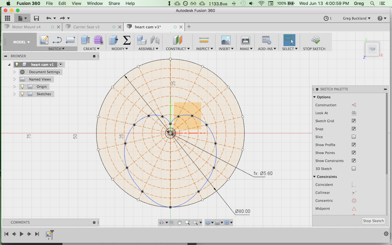
- The curve is then drawn through the intersections of the concentric circles and the radiating lines.
- I used the spline tool to create a curve along said intersections. The result looked pretty good
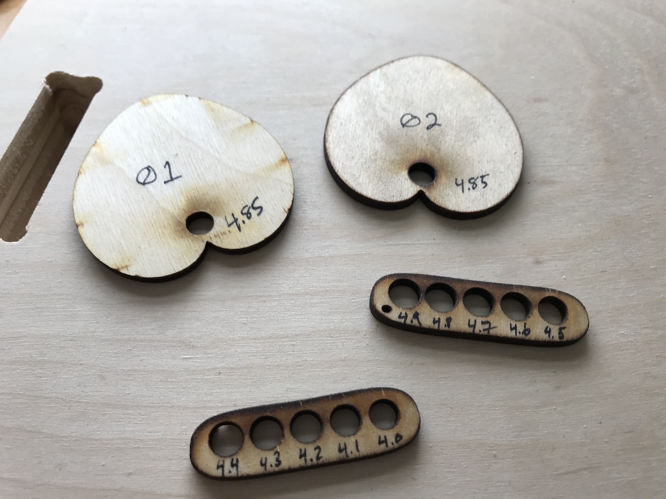
I exported the sketch to a .DXF file and used Convertio.com to convert that to an .SVG file. As Neil mentioned, DXF format is a mess, and I strongly prefer to work with SVG (in Inkscape). There was a scaling error with the conversion, so I did some tweaking in Inkscape, and then laser cut my first cam. The axle hole was too big (the cam slipped freely around the axle, so the motor couldn't transfer any power to the cam) - so I made some test parts to try different hole diameters and see what was the best fit:
I grabbed the ends of my cradle from Week 07, since those were now scrap and they had a nice hole to give the cam clearance to rotate. I screwed the motor mount into the cradle ends, and set the rocker up for the very first test.
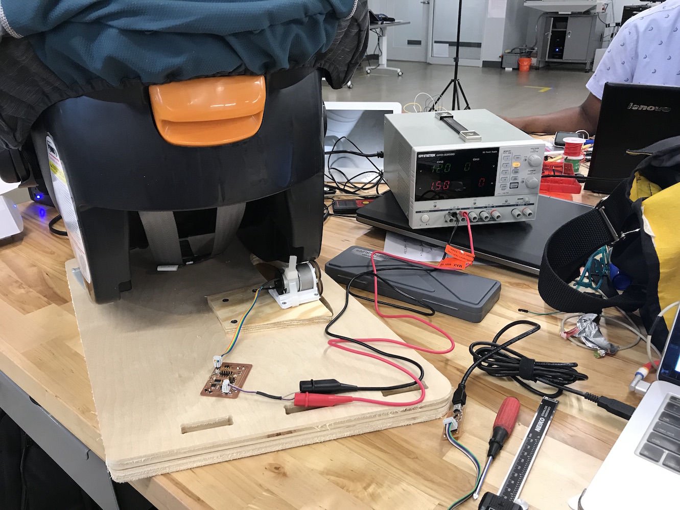
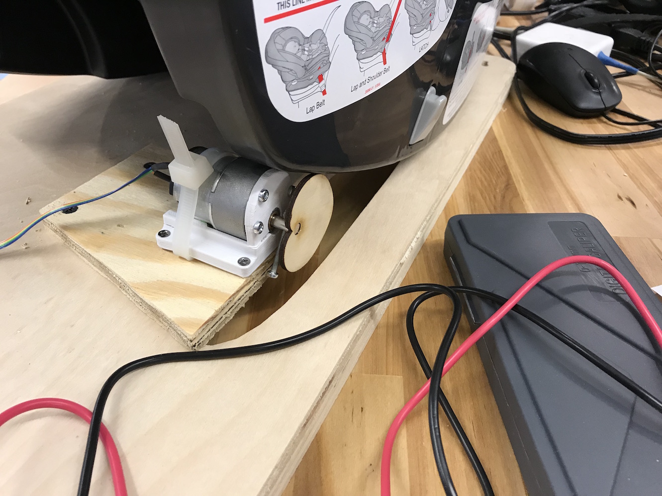
I used my motor controller board from Week 12 and used a slightly modified piece of code. This code takes a button press input to cycle the motor through 4 different states: off, slow, medium, and full speed:
HelloDCmotor06a-push-button.ino
//this one toggles through a preset list of speeds in one direction
//each button press advances through the list:
//[off, slow, medium, fast]

#define in1 6
#define in2 7
#define buttonPin 0
#define off 0
#define slow 100
#define medium 175
#define fast 255

int counter = 0;
int counterMax = 3;
int buttonState = 0;

void setup() {
  pinMode(buttonPin, INPUT);
}

void loop() {
  // put your main code here, to run repeatedly:

  buttonState = digitalRead(buttonPin);   //read the button

  if (buttonState == LOW){    //if button is pressed
    delay(200);     //give user time to press and release button
    if (counter >= counterMax)    //if counterMax is reached
      counter = 0;      // reset counter to 0
    else
      counter++;      //otherwise, increment counter by 1
  }

  switch(counter){
    case 0:
      analogWrite(in1, off);
      analogWrite(in2, off);
      break;
    case 1:
      analogWrite(in1, slow);
      analogWrite(in2, off);
      break;
    case 2:
      analogWrite(in1, medium);
      analogWrite(in2, off);
      break;
    case 3:
      analogWrite(in1, fast);
      analogWrite(in2, off);
      break;
    case 4:
      analogWrite(in1, off);
      analogWrite(in2, off);
      break;
    case 5:
      analogWrite(in1, off);
      analogWrite(in2, slow);
      break;
    case 6:
      analogWrite(in1, off);
      analogWrite(in2, medium);
      break;
    case 7:
      analogWrite(in1, off);
      analogWrite(in2, fast);
      break;
    default:
      analogWrite(in1, off);
      analogWrite(in2, off);
      counter = 0;
      break;
  }

}
Note: Cases 4-7 above should never actually be reached and could be deleted from the code; they are from a previous version that also drove the motor in reverse.
The test was pretty dismal, but I learned a lot:
As you can see in the video, on the low speed setting, the motor doesn't have enough power to rock the carrier. On medium, the cam started to slip on the motor shaft. On fast, the cam slipped, and also it pushed the rocker to the side, offsetting the alignment such that the cam then missed the rocker entirely. I tried a few more tests, but they all had the same results. I learned that a) the low speed setting isn't strong enough b) the high speed setting is strong enough, but much too fast c) the cam slips too easily and needs to be fixed to the drive shaft more securely.
Fixing the cam to the driveshaft was easiest; nothing a little hot glue couldn't fix:
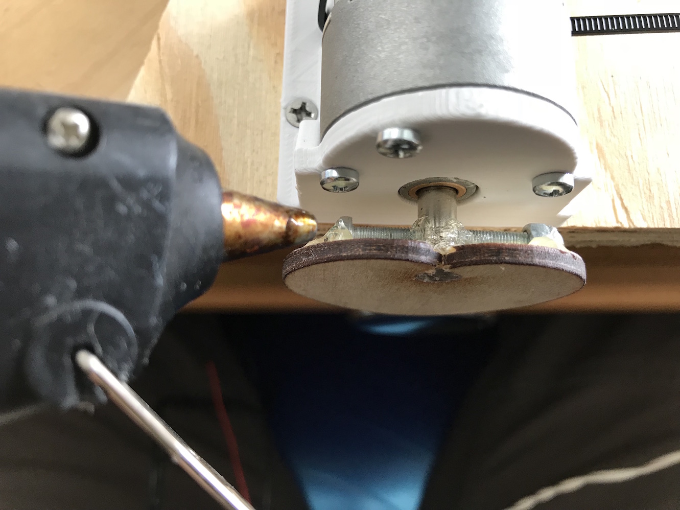
After the hotglue, the cam no longer slipped, and I could stop the motor with the cam, even on full power (though on full power it took substantially more force than on low or medium).
The other two problems (too little power on the low speed, and too much speed on high) could both be solved by a single solution: gearing the motor down even further. I was a little daunted by the prospect of making my own gears, but as I slept on the problem I dreamt that I made a gearbox out of Lego . "Of course!", I thought when I awoke. So I traipsed down to my basement and broke out my Lego collection, which I had thankfully organized a few years back, and could easily find the parts to make a simple 2:1 ratio gearbox.
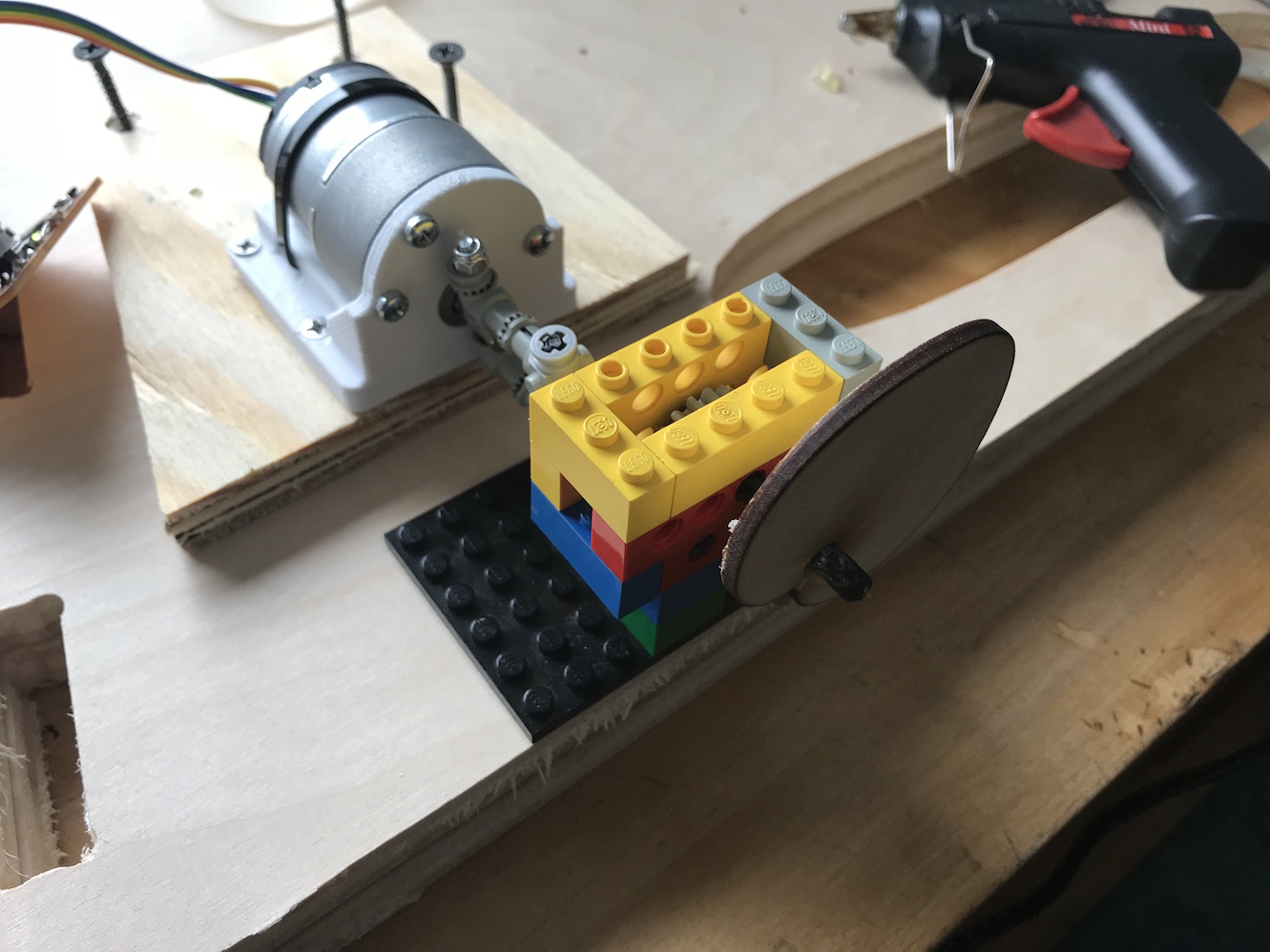
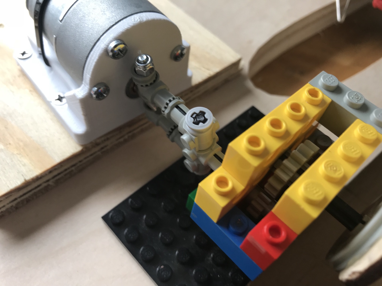
The gearbox seemed to work quite well. (Note: I can reverse the direction of the motor with code, or by simply reversing the polarity of how I plug it into the drive pin header on the motor control board. A handy feature, since the gearbox reversed the direction of rotation.)
Half the speed and double the torque is pretty much just what the doctor ordered for my use case. Even using this same cam, which is far from ideal (see notes below), I had much better luck.