

Success is a journey, not a destination
Objectives:
- Characterize settings for laser cutter on test parts by varying the cutting settings
- Use Vinylcutter to cut something like logo etc.
- Make a parametric design for a press-fit construction kit, accounting for the laser cut kerf
Learning Outcomes:
- Characterizing laser cut machine in terms of power and speed and anlyzing the results obtained from test parts
- Designing a parametric press-fit construction kit for laser cut
- Documenting your design and procedures
- Using Vinyl cutter machine
Task 01. LASER Cutter (Group Task)
Laser cutting is the process of using a powerful laser to cut and/or engrave items from flat sheets of material like wood,cardboard, acrylic, and many other materials. Laser cutter can perform vast array of jobs like prototyping, stamps, signage,jewllery,as well as mass production jobs. The Laser cutter directs a precisely chosen beam at an object either to engrave (Raster) the material or cut right through (Vector).There are a few settings required for Rasterizing and for creating Vector or a combined job can be performed too.
This was my first ever exposure to any Laser cutting machine, I was excited to make some laser cut objects. We have EPILOG LASER FUSION m2 in our lab, which is a 75W CO2 Laser with a bed size of 32'' x 20''.
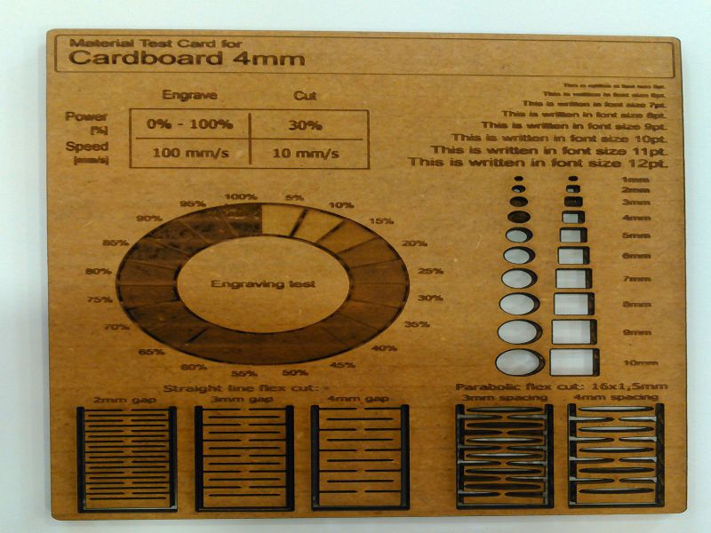
For the Group Task, the objective was to design some test parts and check the performance of machine for different materials. We used a 4mm cardboard to test the power and cut for both engraved and vectored drawings.Engraving and cutting accuracy ws checked on different fonts, different sized shapes, parabolic and straight line flexes by varying line spacing.Following steps were followed to make the design and then performing Laser Cut job.
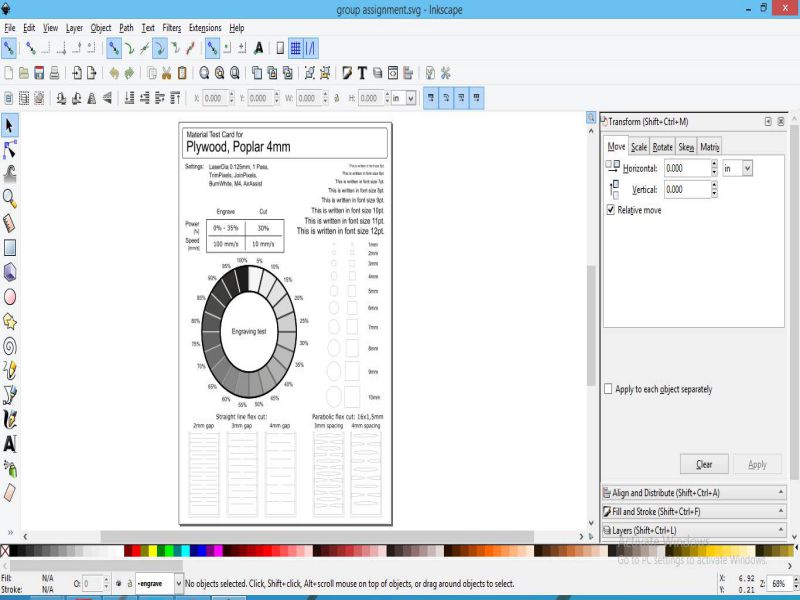
- Chosing a sample design from internet Material Test Card for Laser Cutting and Engraving.
- Open the SVG file for making the Inkscape SVG file as per our requirements of different fonts, Engraving arts, and cut through parts.
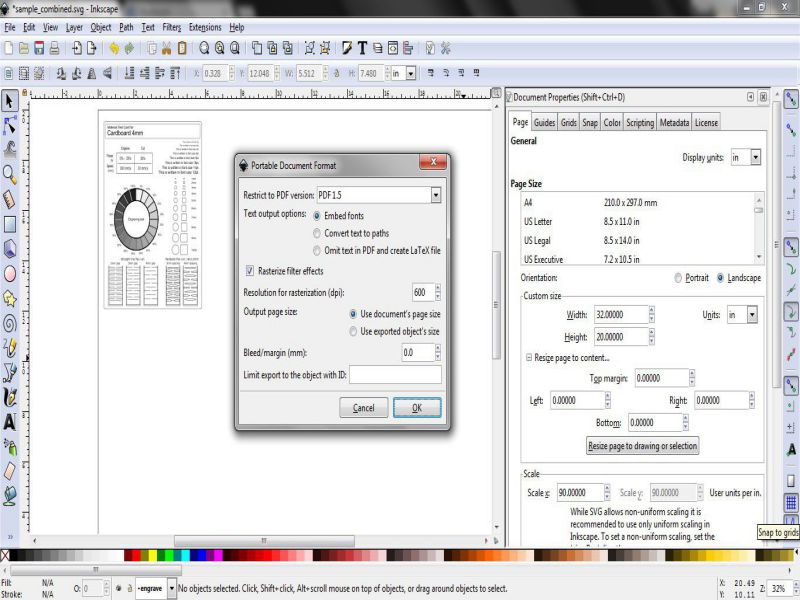
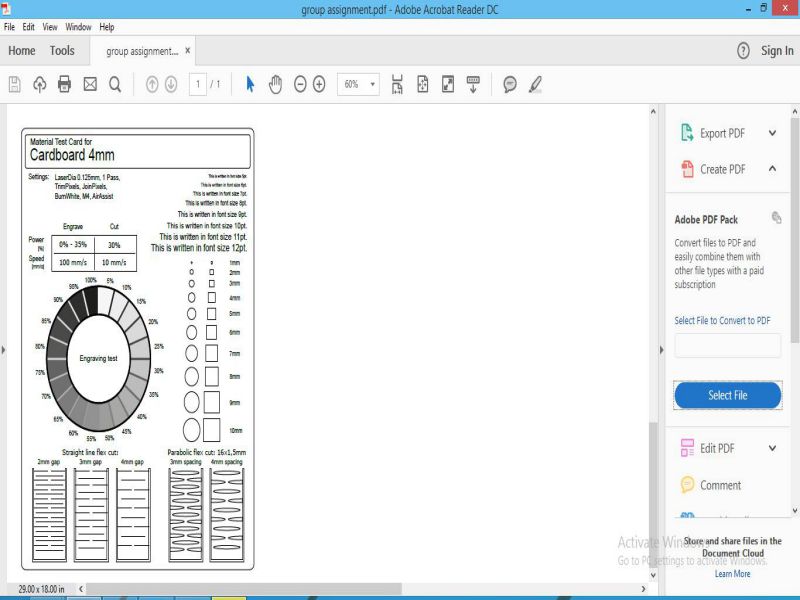
- Making the pdf files of the SVG for printing and test it on varying LASER cut properties ( Power and speed for Engrave and Vector).
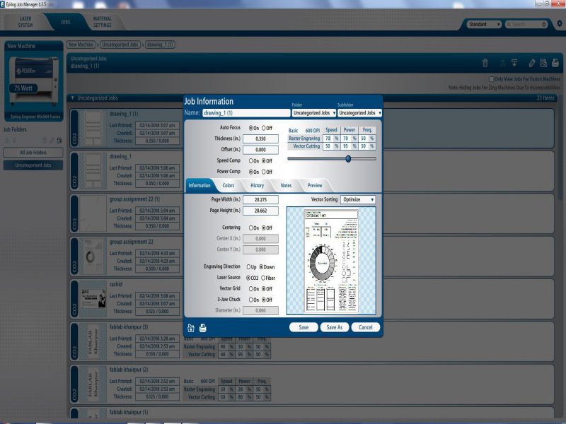
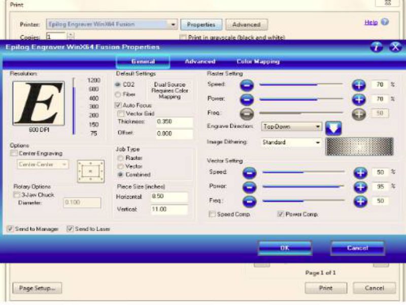
- Now open the PDF file and press Ctrl+P to open printing properties, Select "Epilog Engraver WinX64 Fusion" in Printer Tab and "click Properties to set Power and speed values for "Raster" and "Vector"
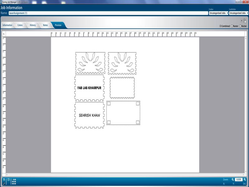
- Now , open the Epilog Manager and click on "Jobs" tab, recent job will be on the topmost. Click on preview to check and confirm your settings. Then, in the bottom-left there is an icon in the pencil shaped, this is used for dragging and setting the position according to free space on printing bed.After selecting the location, save it and then click on "print". The job is now ready for Laser cut.
In this SVG file, we set document properties first, set the page size as (32"x 20") and resolution for rasterization equlas to 600 dpi.The value of line stroke is kept '0.001 inches as per our machine's requirement for cut through.
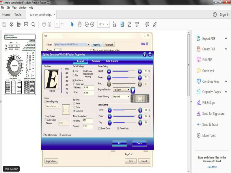
Click on combined in "Job Type". The Raster power and speed are kept 100%. and Cutting power for Vectoris kept at 30% and speed at 10%. When these setings are done, click "OK" to transfers the Job to Epilog Job Manager and click "print".This is shown in the picture given below:
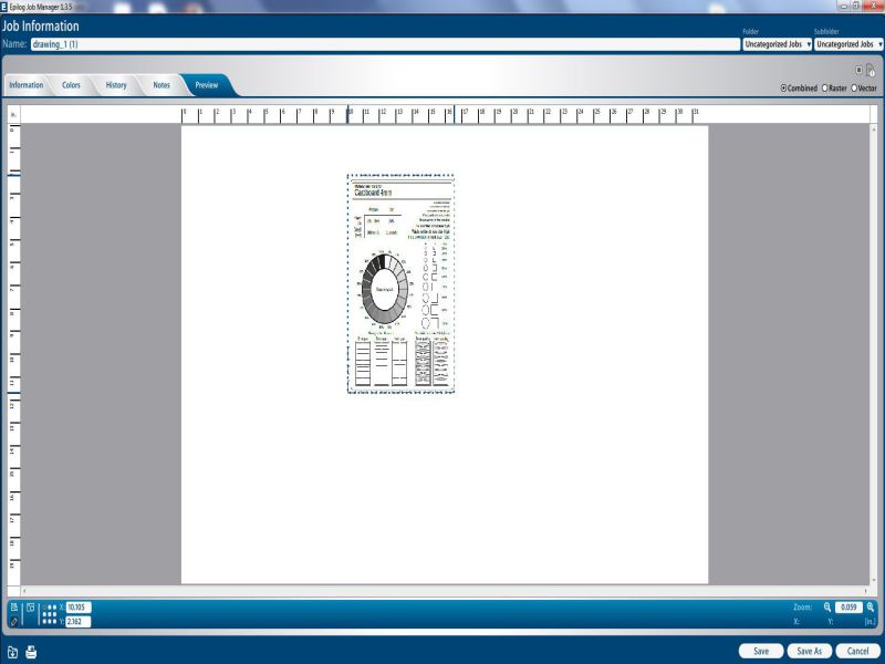
The job is shown on the machine interface, click on "GO", then your job is done and rest is performed by Laser cutter.
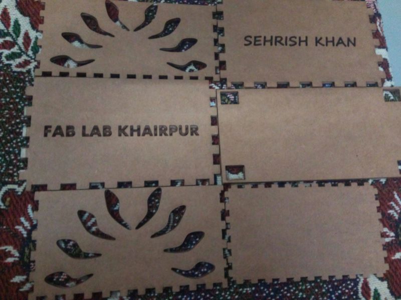
The LASER has performed its Job dexterously! Check the results below:
Learning Outcomes:
- The performance of LASER cutter mainly depends on Power and Speed.
- The power and speed needs to be varied according to material thickness and type and the type of job- Engrave or Cut through.
- If power is too high while the speed is too low, then this can result in buring.
- If the speed is too high and the power is too low , then engraving will done fine but the cut through job might not be performed well.
Task 02. LASER cutter (Individual Task)
The objective of this task was to design a Parametric model, which can be Pess Fit in construction. I decided to make a Press Fit Box for this assignment. I used Solidworks to make the parametric model and to check PressFit simulation.
Part1: Parametric and Press Fit Model Design
I started working on solidworks, because I have practiced on it in Week 03 as part of the assignment. I knew the basics of the Solidworks, so I just watched some useful tutorials on youtube and on official website of solidworks .In the previous week , I had learnt to make parts and create Assembly from those parts.
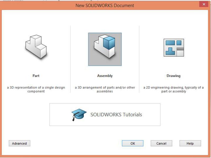
- Open the solidworks Software
- Select New File > select the part option
- Set the document Units for measuring, I set IPS (Inch Pound Second)
- Now, select the plane on which you want to create your first sketch
- I selected Boss extrude becuase I want to give my object a particular thickness> then sketch becuase I want to give it a shape of rectange> selected Rectangle and drew it on front Plane, as shown below:
- After making a rectangle, click Extrude Boss base to give thickness to the object, select the blind option and in the field given as "Depth", give value.
- Then I wanted to create fingers, so that my box can become Press-Fit
- I drew a single finger , and then replicated it using Linear Sketch Pattern.
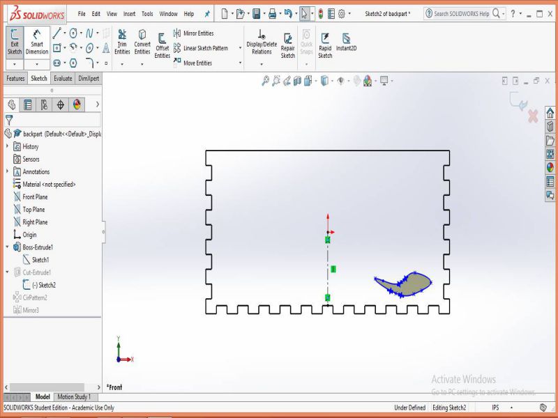
- Now, I drew a shape using spline, using spline is easy , but it takes time to make a proper shape. As I wanted this shape to be cut through, so I selected cut Extrude before drawing this sketch. Once my spline shape is completed, I selected exit sketch to give thickness to the part I want to cut. Instead of selecting "sketch plane" , click on "through All" as we want this part to be cut through all.
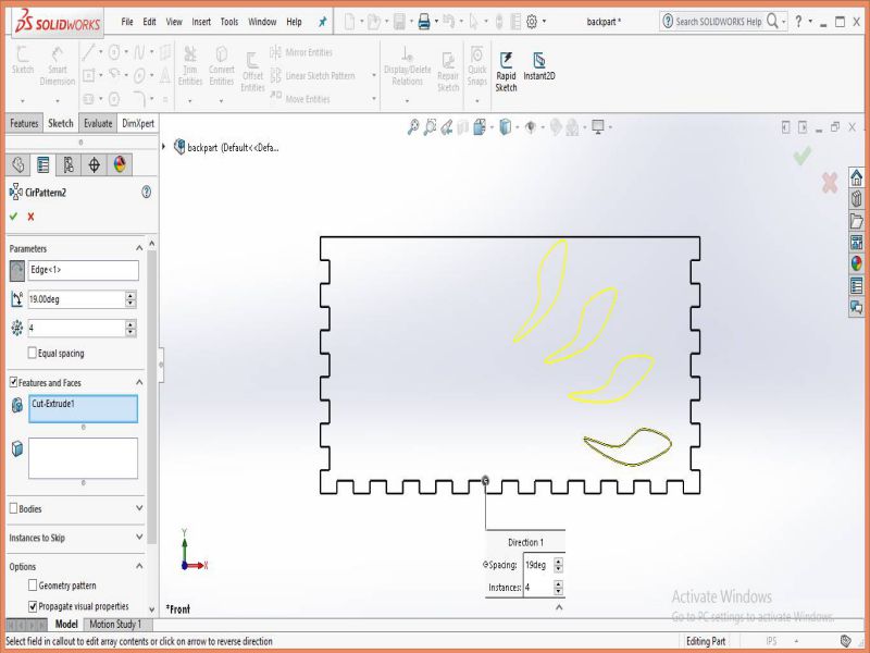
- In order to make more copies, I used circular pattern
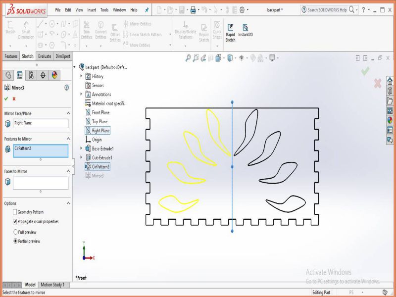
- This makes the copies on one side, to make the same shapes on the other side, I used Mirror option to create on the other side of the plane.
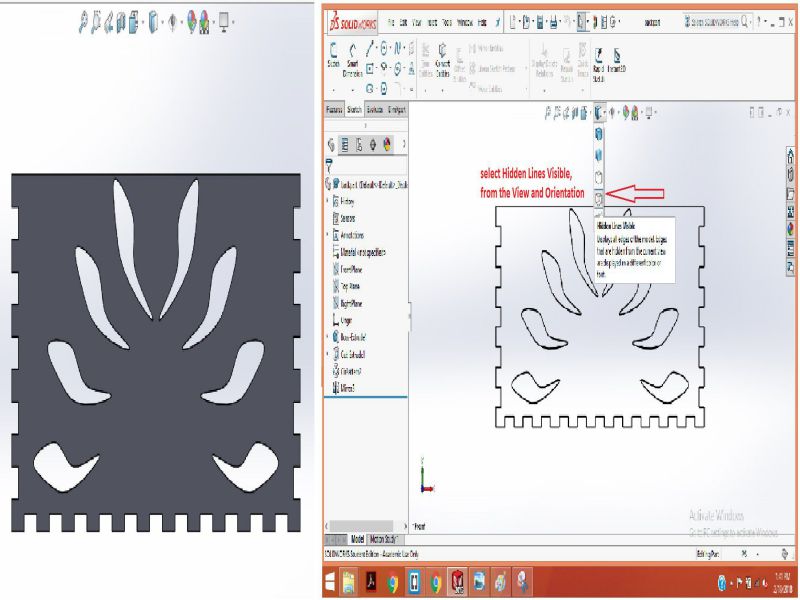
- In order to make the lines clear, go to View and Orientation panel and select the hidden lines visible option.
.jpg)
.jpg)
.jpg)
Set the dimensions using Smart dimensions tool and then click on green tick mark to apply the changes.
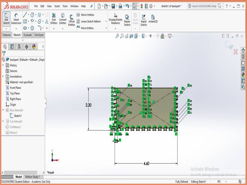
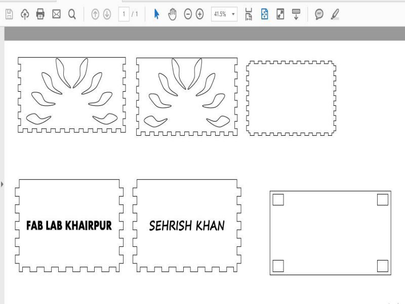
This is the complete 2D Drawing of the of the box. I copied the front part to make the rear part.
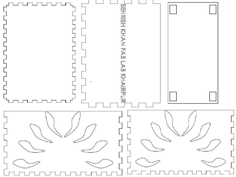
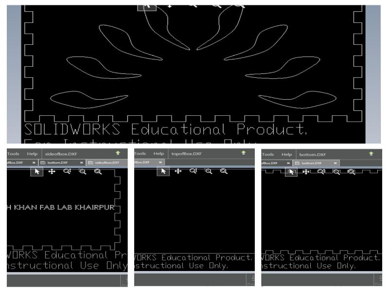
I made a DXF file for each of the part by saving the file with .DXF extension. I can use this DXF file to make any changes to the 2D drawing in Inkscape.
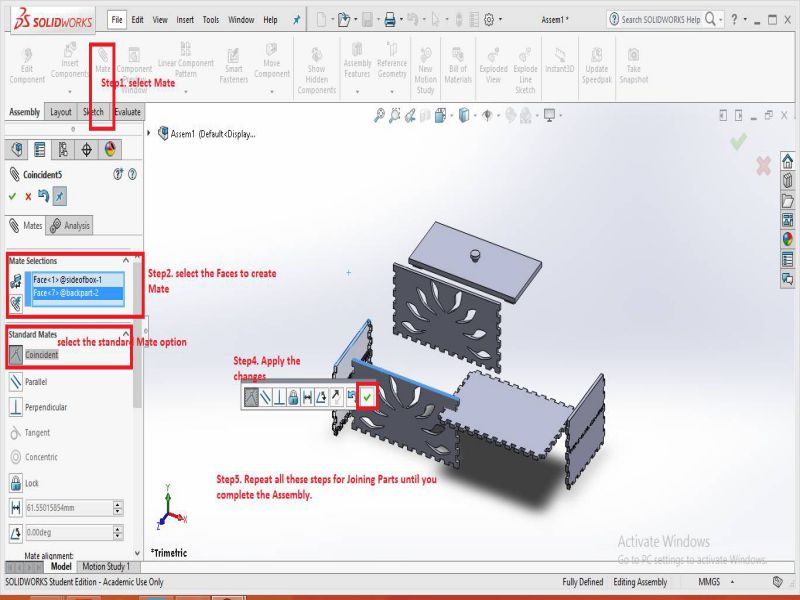
The next thing I wanted to do was to check if the parts were making a Press Fit construction. I joined all the parts using the Mate tool. The steps are given below:
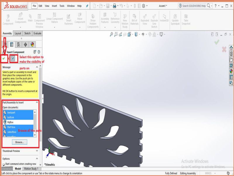
- Open a new File> click on Assembly
- Now, open all the arts by clicking on 'inset components' and browse all the parts .
- Click on each part to place it in workspace environment.Then, to connect all the parts, select the 'Mate' option, select coincident Mate, and select any faces to create mate between them. Follow the same proceure until you connect all the sides and faces to make a box.
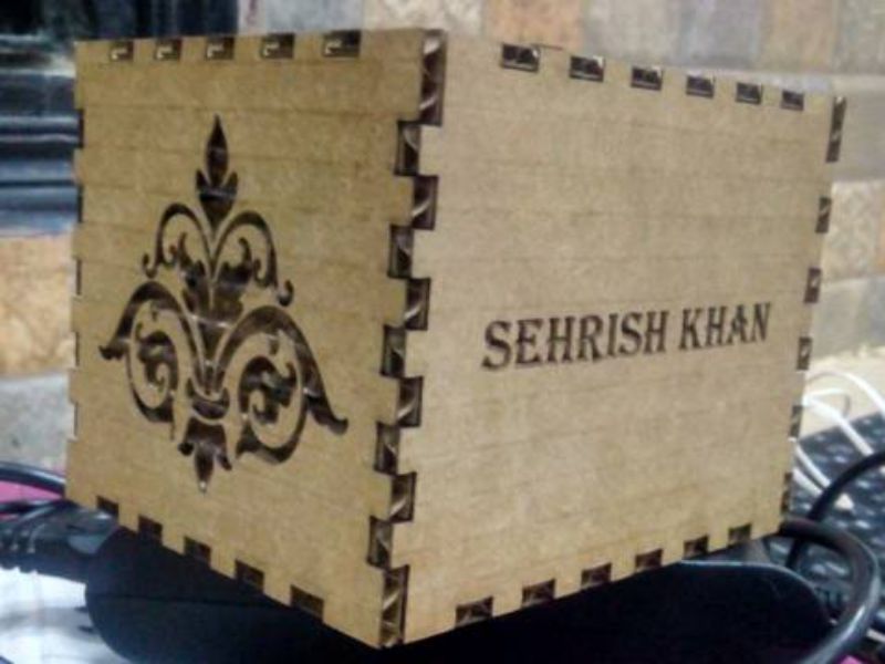
This is how the complete box looks like in 3D view.
This completes the design process.
Part2: Making the file ready for LASER cut
- Open the DXF files in Inkscape and set the document properties as described in the GRoup task above. Set the stroke line for cut through equals to "0.001 inces"
- Save the file in the .pdf format
- click on printer > select Epilog Engraver Win64 Fusion > click on properties to set the Power and Speed for Raster and Vector, also select "combined" because we want to perform engraving and cut through also.
- Start the Epilog manager> click on Jobs> click on the recent job .
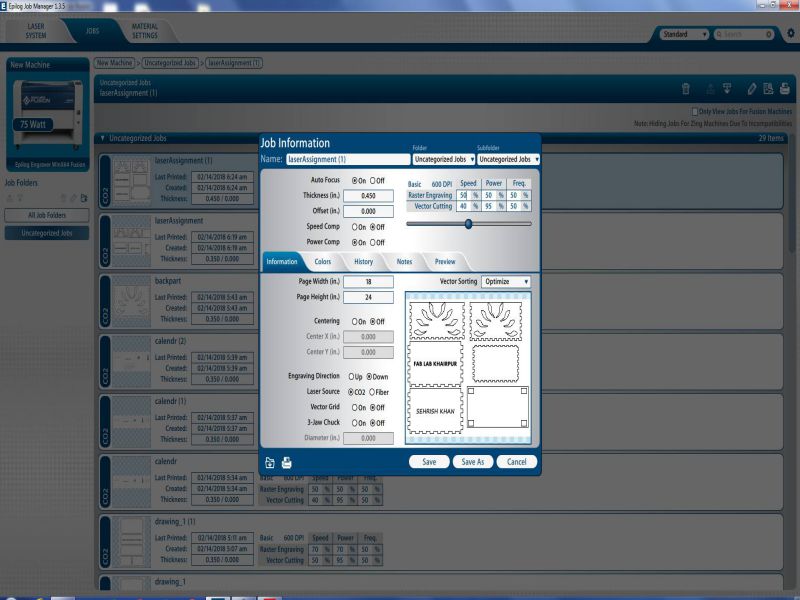
Set the position using , then click save.Then finally click on print and select "GO" on printer. The Job starts for laser cut.
| Basic 600 DPI | Raster Engraving | Vector Cutting | Frequency |
|---|---|---|---|
| Power | 50% | 50% | 50% |
| Speed | 40% | 95% | 50% |
The LASER cutter performed its job very well.
The Laser cut box is shown below.
Part 3: Issues in connecting the LASER cut Press fit parts
After cutting the LASER parts, I tried to join them , but I had not created the offsets properly. So, my parts were not connecting with each other properly. I tried to make some changes in the solid works design. Then the issue of ofset was overcome. This time, the press-Fit box was ready and it made a perfect Press fit Box.
Learning Outcomes:
- Making a Parametric 3D model in Solidworks
- Adjusting Power and speed for raster engraving and vector cutting
- Creating a Press-fit construction
Task 03. Vinyl Cutting
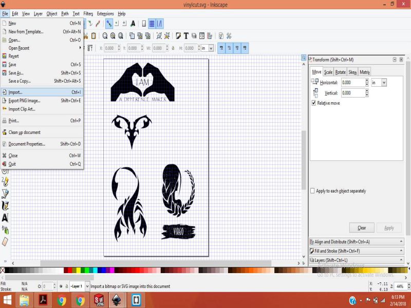
Vinyl Cutter is a machine that is used for trimming Vinyl and other materials into many shapes or letters.It is basically a cutting device controlled by computer.Computer controls the movement of sharp blades of the Vinyl Cutter.These sharp blades are responsible for cutting shapes or letters rom the adhesive sheets of Vinyl materials. The shapes can be simply cut from the Vinyl material and pasted or transferred to a transfer paper then pasted on the desired surface. We have Roland GS-24Vinyl cutter in our lab. I like the Zodiac Signs , so I decided to make some. I followed these simple steps given below.
Making Images ready in Inkscape
- Importing the image into Inkscape.
- Now select the image and click path to object
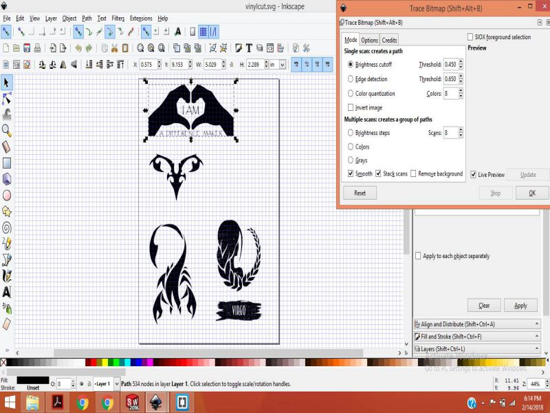
- Select the same image and click Trace Bitmap to make the traces of image
- Keep the bitmap image, and delete the older one
- Save your image as jpg or PNG
The next step is to open this image in "Cut Studio" by following the steps given below:
Importing the Image into Cut Studio
- Open the image in the Cut Studio
- Select the image and set its dimensions using size and shape
- Right click the image and select image outline
- Seect image contour option
- Keep this updated image and delete the original one
- Making the machine settings, then press cut.
.jpg)
.jpg)
The image is ready to be cut on Vinyl Cutter, set the adhesive Vinyl paper and do some position adjustment on Roland machine.
Setting the Rolland Vinyl Cutter
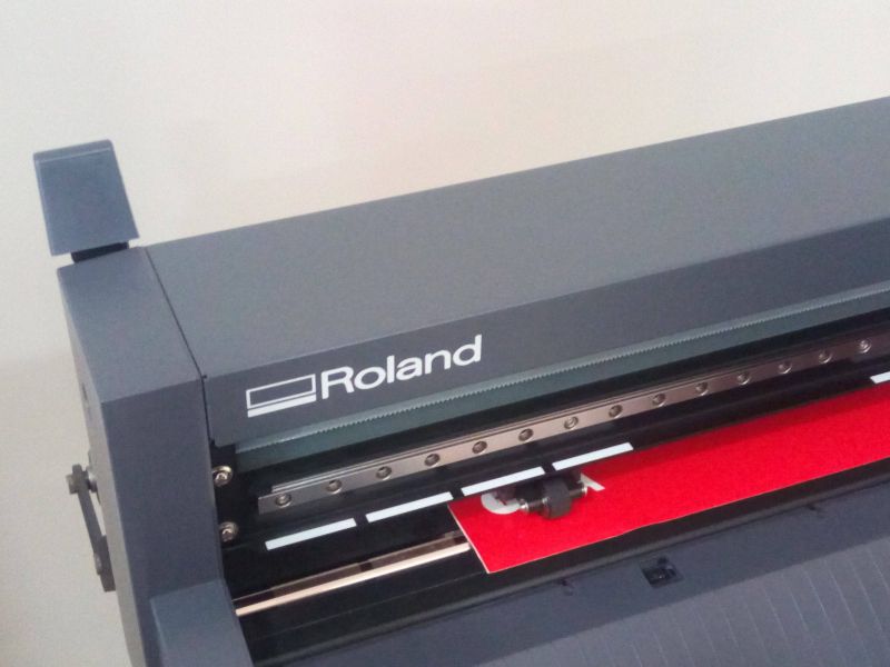
- Place the vinyl paper
- Align the paper with the white markers given, the paper holders (wheels) should also be aligned with the white markers otherwise you get 'bad position' message on the display
- After placing the paper in the position, go to LCD display (Machine interface) and set the sheet to 'piece', then it will give the length and width for the piece
- Select 'cutting' option in the cut studio
- Now the machine starts cutting the given shapes
The GIF given below shows these steps performed in sequence on the Rolland machine.
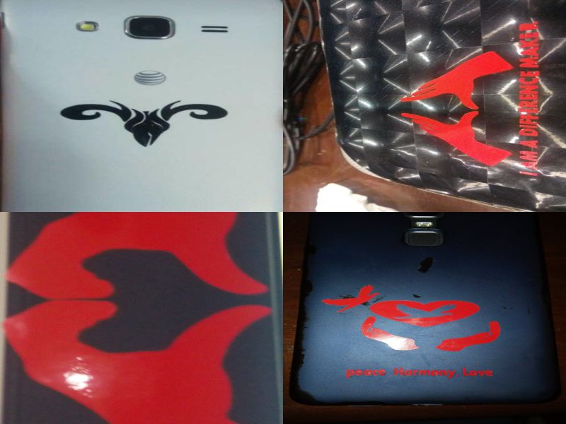
Results for Vinyl Cut
These are my Vinyl Cut stickers
This ends my Week 04 here :)
Download all the Files of this week Below:
Click here to check my final project idea
Check out About me and other details here

This work is licensed under a Creative Commons Attribution-NonCommercial 4.0 International License.