

Success is a journey, not a destination
Objective:
- Make an In-Circuit Serial Programmer (ISP) by milling the PCB
Learning Outcomes:
- Making an In-circuit Serial Programmer
Group Task:
For group assignment, we have to characterize the specifications of PCB production process and for that we are using Roland monoFAB SRM-20 Milling machine. For learning process in both group and individul assignments we are using basic PCB Board which is FR-1. We are fabricating a Traces-width board, which has a traces which is very near in different sizes. For cutting and traces we are using 1/32 and 1/64 drill bit respectively.
Fabricating PCB
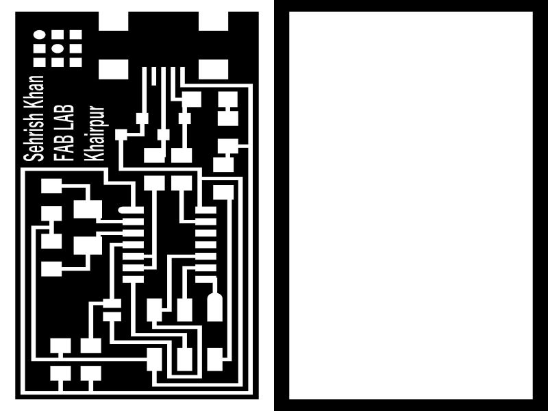
We are using these png files for trace and outline


Learning Outcomes for Group Task:
From this task we come to know how thin the traces of milling the PCB can be made using 1/64 tool used for traces and 1/32 tool used for cutting outline.
Individual Task:
When we talk about Electronics and Embedded systems , we mostly refer to microcontrollers and programmer boards. The best thing about an ISP (In-System Programmer) is that you can easily reprogram the microcontollers and external memory chips without removing it from the board. This week's task covers the same objective of making an AVR microcontroller that can be used to program any AVR microcontroller. This will also be helpful in the upcoming assignments also like ,"Circuit Designing", "Output Devices".
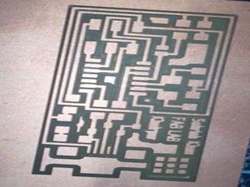
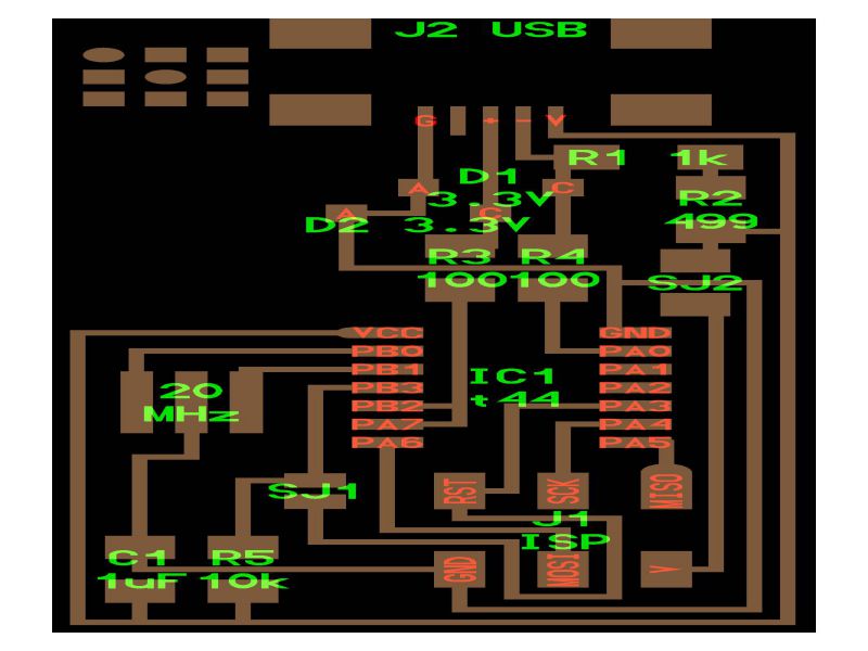
In order to do the milling on PCB, I used the PCB layout provided during class. The traces and Outline is given below. The drilling was not required as shown in the schematic below:
Part 01- PCB Milling:
Following steps were required for the PCB milling:
- Generating the RMl files from mods.cba.mit.edu/
- In the program tab, click on open server program
- Click on PCB under SRM-20
- Click on image(.jpg) as your input format file
- Browse and open your desired png file
- After opening your file, select mill traces 1/64
- Go to the modules tab and click on add server module
- Click on save
- A pop-up will appear as shown below, drag this file and connect it to the output node of Rolland SRM-20 milling machine
- Click on "Calculate" and the file will automatically be saved
- Your RML file is ready
- To check the traces and path of PCB , click on view
- Select the png format of outline and click on mill traces 1/32 and click calculate to save this file.
Following are the required steps for generating RML files.
This GIF image shows all the steps mentioned above:
- Milling on PCB Using ROLAND SRM-20
- First of all, turn on the power
- Select the appropriate tool , 1/64'' for traces and 1/32'' for cutting outline.
- Open the VPanle software for Roland SRM-20
- To set the tool, you need to adjust the position(x,y , z) in user coordinated system using the software.
- Tighten the tool first, then set the x and y position, and then the z-position.
- When you have set the xy,z properly, then click on spindle to check if the amchine is performing milling.
- Now turn the spindle off, loosen the tool and fix it again.
- In the next step, clear the xy values, and set the value for z then click on cut> delete all> add , then select output.
- Now the machine will start to mill
- Try to adjust the position of the tool properly as it is very thin and if you do not set proper position of 'z-axis' then it can be broken.
Following are the steps required for setting the position on ROLAND SRM-20 and then do the milling task:
The GIF image given below shows the GUI of VPanel and the steps mentioned above:
Now, the machine is all set, and busy in performing its task very well.
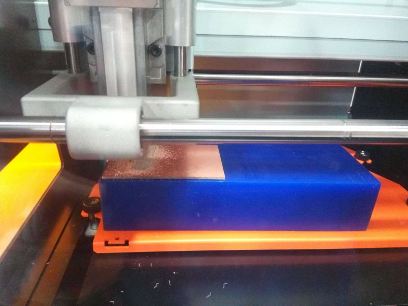
The results are here, satisfying and motivating you to work further:
Part 02- Soldering of ISP:
Following steps were required for the SMT based soldering on PCB
- Making a List of components as shown below:
- Following image is useful for checking the polarity of components like Zener diode and ATtiny44.
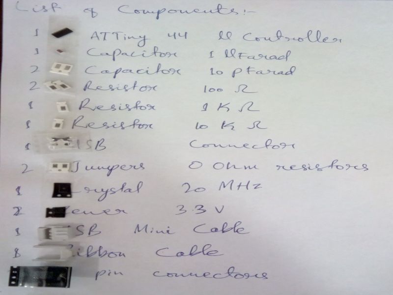
Following components were required for soldering:
- Soldering Iron
- Soldering wire
- Desolder
- Tweezer
I have never done soldering on SMT before, so I did a bit of practice first and then I soldered my PCB. It took me time , but good results always take time.

Part 03- FabISP Programming:
Following steps were required for the programming of ISP:
I used Ubuntu Operating System for the programming purpose. Following steps were required for the programming of ISP :
- Installing the necessary softwares for AVR Programming.
- Avrdude (for programming AVR microcontrollers)
- GCC (to compile C code)
- Open the termianl and type following commands:
- sudo apt-get install flex byacc bison gcc libusb-dev avrdude
- sudo apt-get install gcc-avr
- sudo apt-get install avr-libc
- sudo apt-get install libc6-dev
- cd ~/Desktop
- wget http://academy.cba.mit.edu/classes/embedded_programming/firmware.zip
- unzip firmware.zip
- Power the FabISP Board:
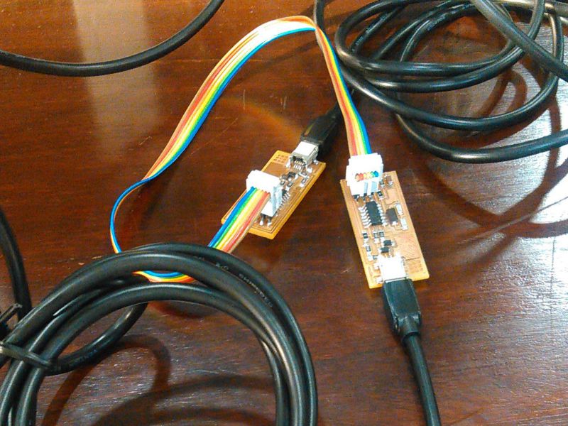
- Pulg in the mini USB connector of your FABISP into computer.
- Make sure you have plugged in another working FabISP in to the 6-pin programming header.
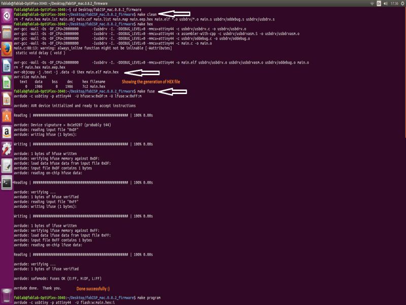
- Program the FabISP by writing following commands in Terminal step by step:
- make clean
- Make HEX
- Make Fuse
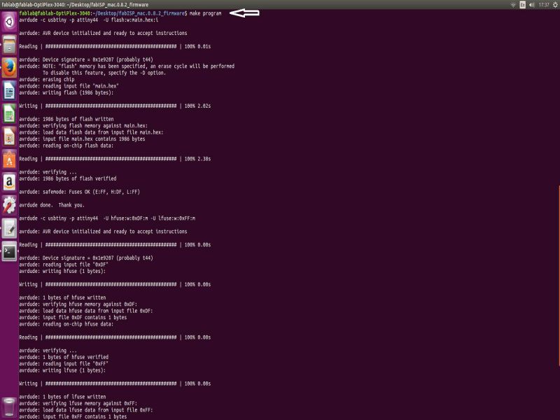
- Make program
- Now. Verify that your ISP is working fine by tyoing the following command in terminal.
- lsusb
- The verification is performed.
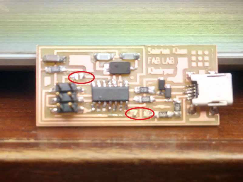
- Removing the Jumpers (0 ohm) resistors:
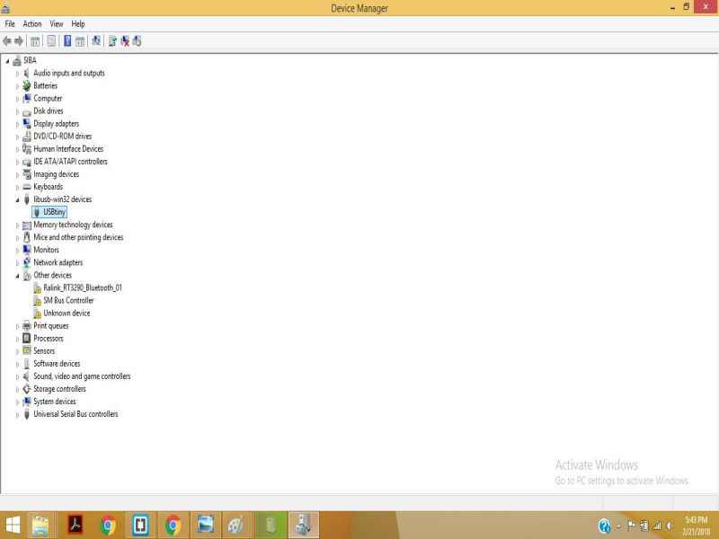
- Last step: Installing the Drivers
- Download the drivers from Here
- Plug in the programmer into computer , then open the Device manager.
Then type
- type "y" when asked to do so by your system
Then type (may already be installed):
Download and Unzip the Firmware:
Move to the desktop
Download the firmware from the Fab Academy Electronics Production page.
Unzip the firmware
Now the fabISP is ready for use :)
The RML files for this week are attached Here!
Click here for the details of my final project
Check out About me and other details here

This work is licensed under a Creative Commons Attribution-NonCommercial 4.0 International License.