

Success is a journey, not a destination
Objectives:
- Redraw the echo hello-world board
- add (at least) a button and LED (with current-limiting resistor)
- check the design rules, make it, and test it
- Download the fab library from HERE
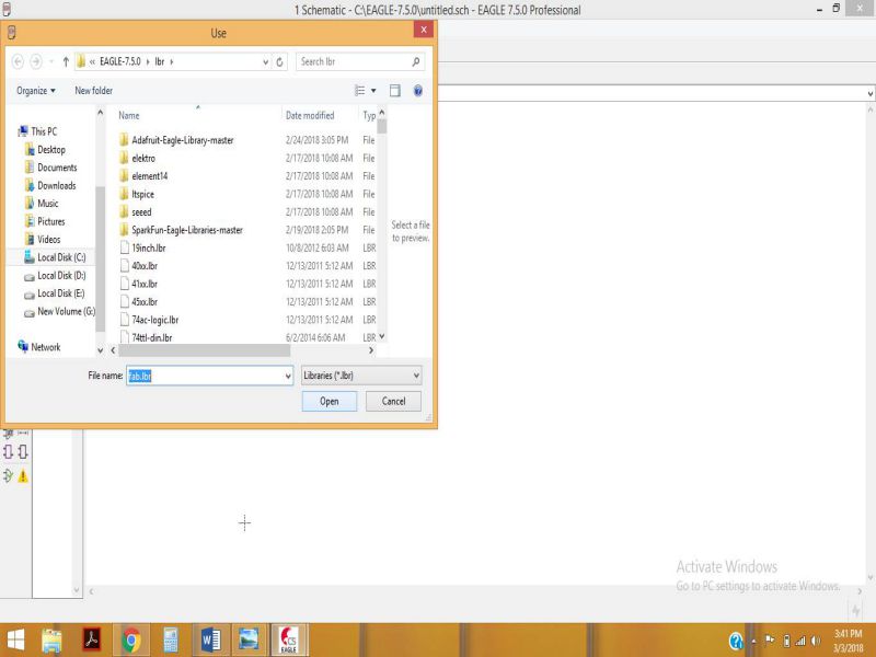
- Go to the Default location where the EAGLE software has been already installed , click on lbr (the sub-directory where libraries are included), paste the "fab.lbr" here.
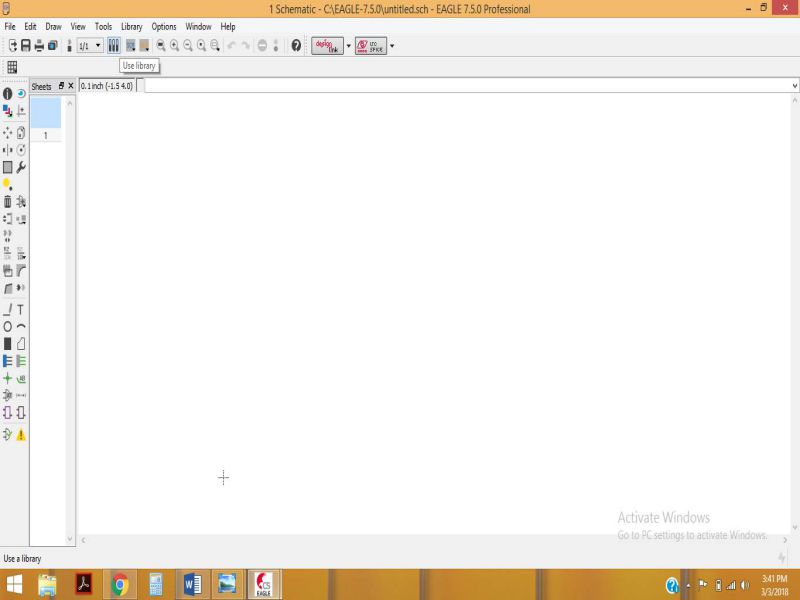
- Now, Open the EAGLE software
- Click on new File, and select schematic. It is better to save your file first and make its board also, this way you won't be getting any error of forward or backward annotation, which is quite annoying.
- Click on use Library and the select fab.lbr
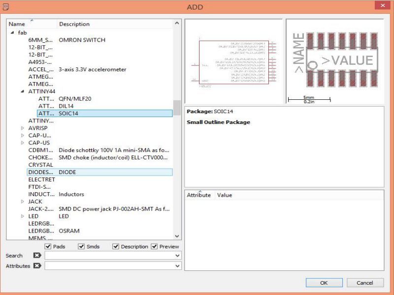
- click on add component and type "fab", this is the same library that we added before. Now select the components required for drawing the Hello World Board as mentioned Below:
- Attiny 44 - 01
- Resonator 20MHz - 01
- capacitor 1µf- 01
- ISP SMD header - 02
- resistor 100Ω - 01
- resistor 10KΩ - 01
- 1x6 Pins SMD header - 01
- Push Button SMD - 01
- LED SMD - 01
- Generating the RMl files from mods.cba.mit.edu/
- In the program tab, click on open server program
- Click on PCB under SRM-20
- Click on image(.jpg) as your input format file
- Browse and open your desired png file
- After opening your file, select mill traces 1/64
- Go to the modules tab and click on add server module
- Click on save
- A pop-up will appear as shown below, drag this file and connect it to the output node of Rolland SRM-20 milling machine
- Click on "Calculate" and the file will automatically be saved
- Your RML file is ready
- To check the traces and path of PCB , click on view
- Select the png format of outline and click on mill traces 1/32 and click calculate to save this file.
- Milling on PCB Using ROLAND SRM-20
- First of all, turn on the power
- Select the appropriate tool , 1/64'' for traces and 1/32'' for cutting outline.
- Open the VPanle software for Roland SRM-20
- To set the tool, you need to adjust the position(x,y , z) in user coordinated system using the software.
- Tighten the tool first, then set the x and y position, and then the z-position.
- When you have set the xy,z properly, then click on spindle to check if the amchine is performing milling.
- Now turn the spindle off, loosen the tool and fix it again.
- In the next step, clear the xy values, and set the value for z then click on cut> delete all> add , then select output.
- Now the machine will start to mill
- Try to adjust the position of the tool properly as it is very thin and if you do not set proper position of 'z-axis' then it can be broken.
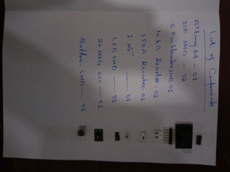
- Making a List of components as shown below:
- Following image is useful for checking the polarity of components like LED and ATtiny44.
- Soldering Iron
- Soldering wire
- Desolder
- Tweezer
Individual Task:
As part of this week's assignment, I need to redraw HelloWorld Board and test it.During the lecture Professor Niel shared many softwares which can be used for circuit Designing, but EAGLE is easy to use as per my opinion. I had worked on EAGLE before, but I am not really an expert at this. The thing that requires some practice is routing, so I watched some youtube tutorials to get may hands on it.
Beofre making the schematic of Hello World board, I need to add fab library to my EAGLE libraries. The fab library provides almost all the components that will be used to make the hello world board. Adding and using a library is shown in the steps below:

The library is now ready to use.
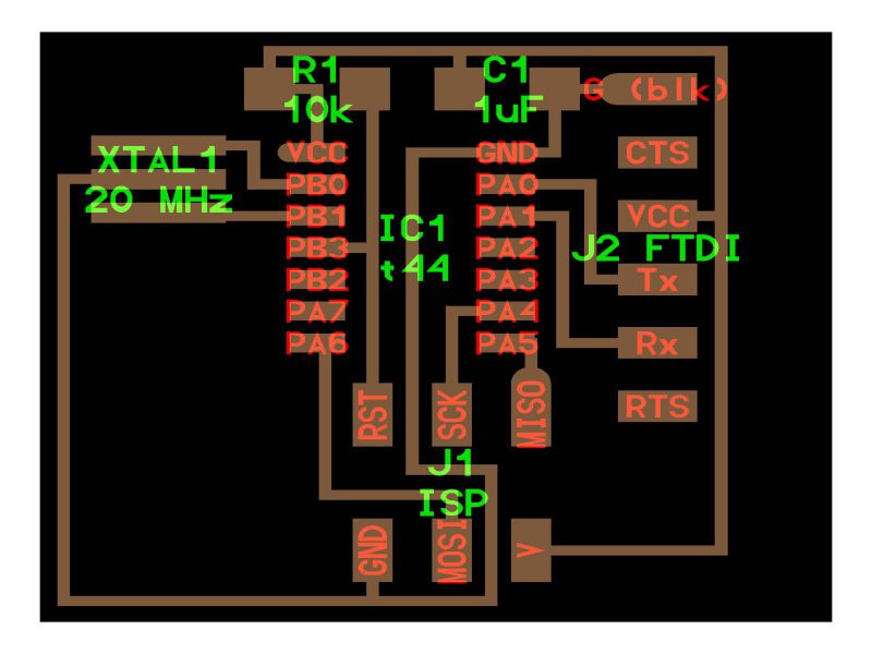
This board contains an ATTiny44 and the other components mentioned above, I need to make some modifications in it so that I can add an LED and button.
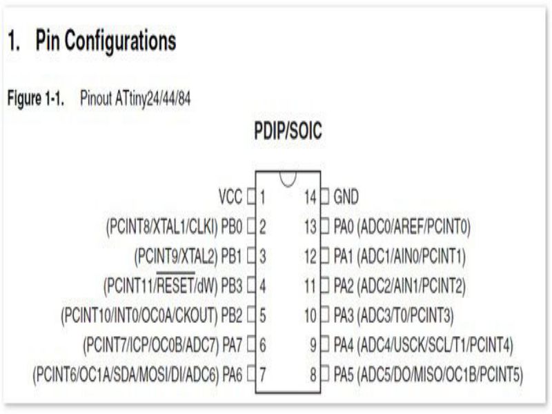
Before making the schematic on EAGLE, I read the Data Sheet of ATTiny , to check about its specifications and pin-configuration, which is given below:
Making Schematic of FTDI Hello World
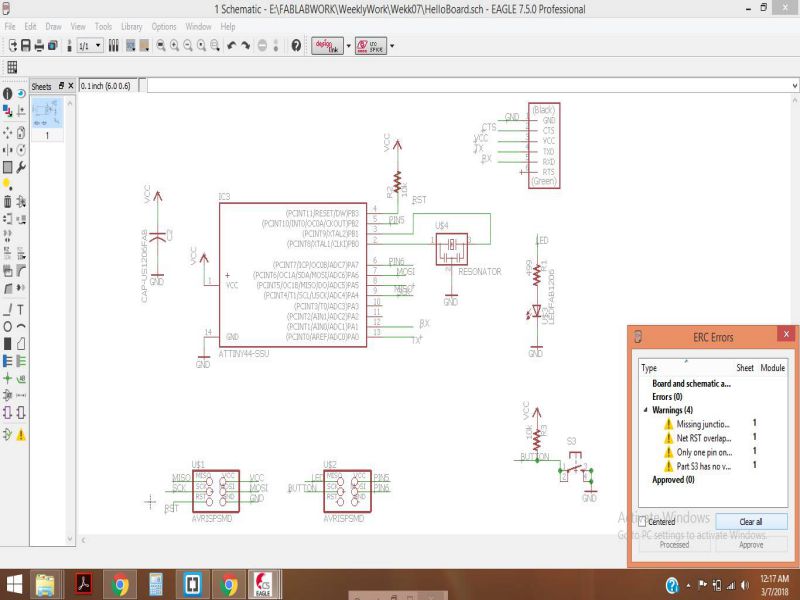
Now, its time to make the hello world board on EAGlE software, I have to add an LED and button in the existing schematic discussed earlier.
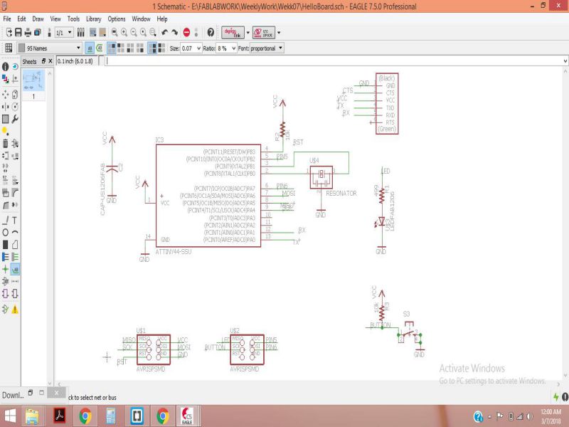
I have added an LED and a push Button, and added an extra 2x3 ISP SMD Header also , to use the extra Input Output pins of the ATtiny44 for my future assignments. As part of my Final project, I need to test it in various steps , so I will be making use of the extra I/O pins.
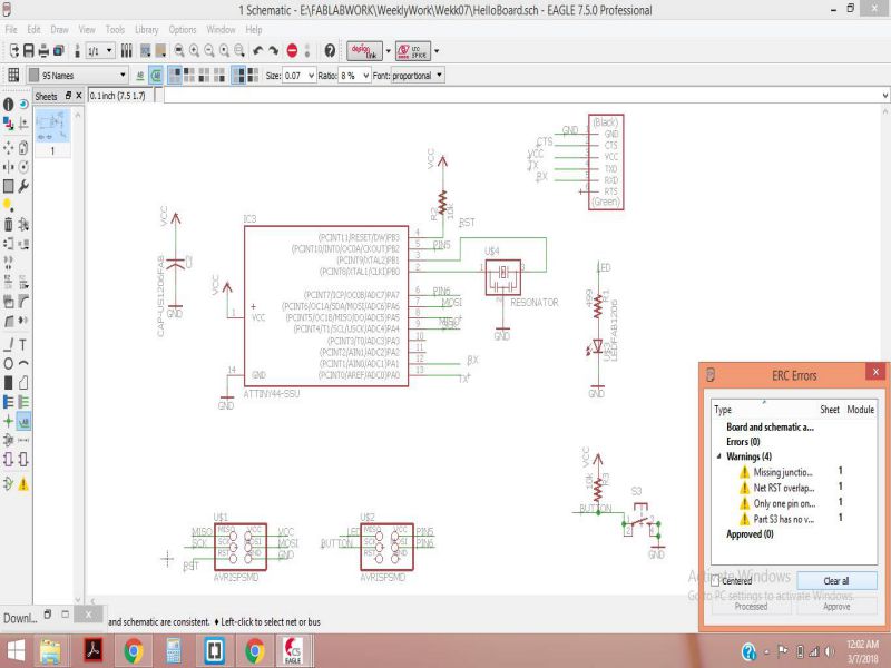
The next step is to check errors , I checked the erros using ERC and cleared all the warnings.
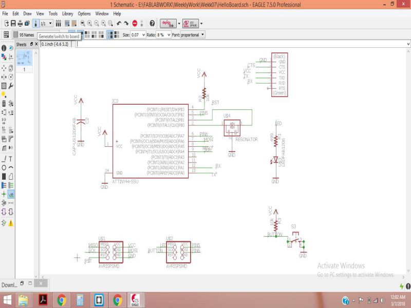
My schematic diagram is done, now I switch to the board. Simply click on the icon, as shown below:
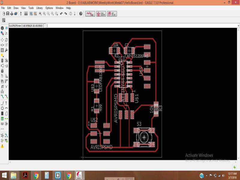
It took me more time to set the components in proper place, initially i did not set the grid properly. Then i set the grid to 0.079375 mm. The other thing that troubled me was routing, but after many attempts I completed it. I had set the Line width equals to the default value of 0.4064, it was doing fine , but there were some connections which were merging with each other. So, i used two line widths, 0.3048 and 0.4064. My board is complete and shown below:
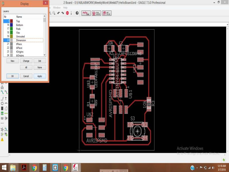
Now, I need to check for erros, but as I had already tried in many attempts to adjust the line width, so this time I did not get any error. Before checking the errors, we need to uncheck all the unused layers from the layer settings.
Now, by checking the ERC, and then clearing the warnings.
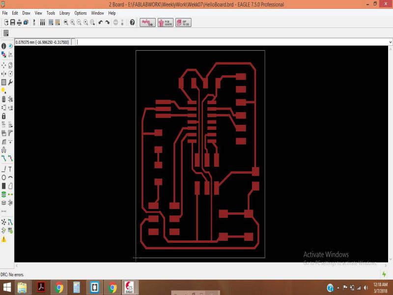
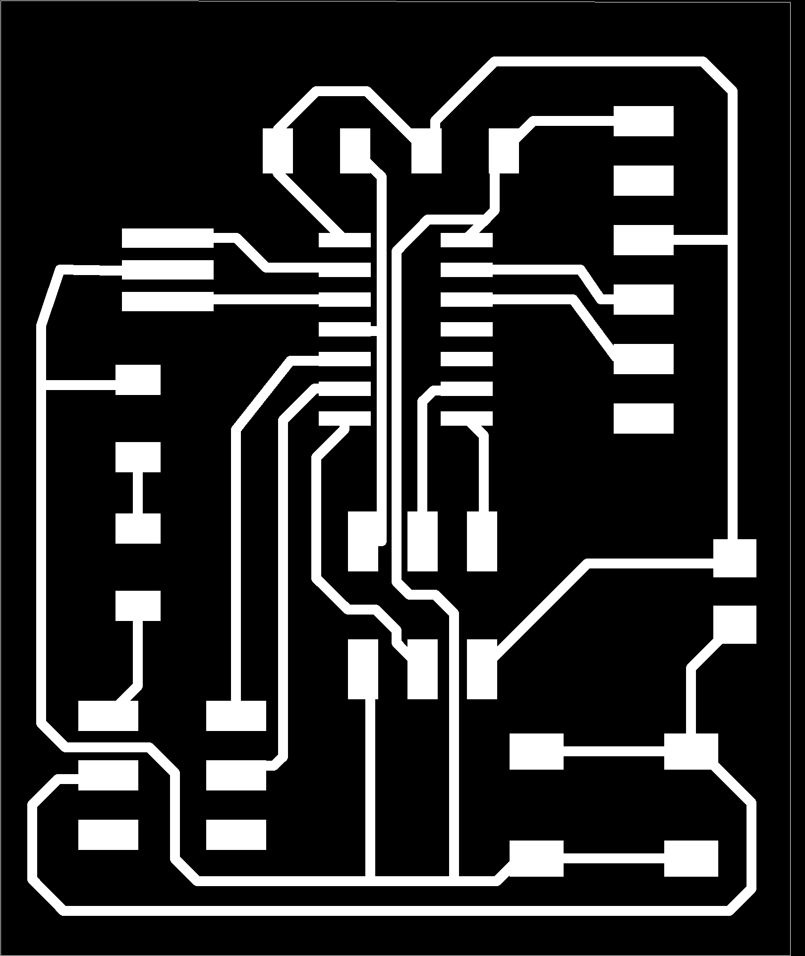
Finally, I have made my Board ready. I just need to export and save it as PNG to generate the RML files.
Generating RML files
In order to do the milling on PCB, I used the PCB layout provided during class. The traces and Outline is given below. The drilling was not required as shown in the schematic below:

Part 01- PCB Milling:
Following steps were required for the PCB milling:
Following are the required steps for generating RML files.
This GIF image shows all the steps mentioned above:
Following are the steps required for setting the position on ROLAND SRM-20 and then do the milling task:
The GIF image given below shows the GUI of VPanel and the steps mentioned above:
Now, the machine is all set, and busy in performing its task very well.
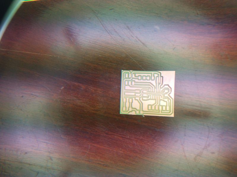
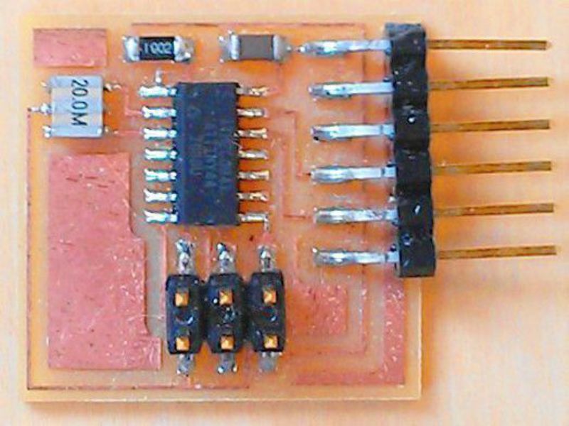
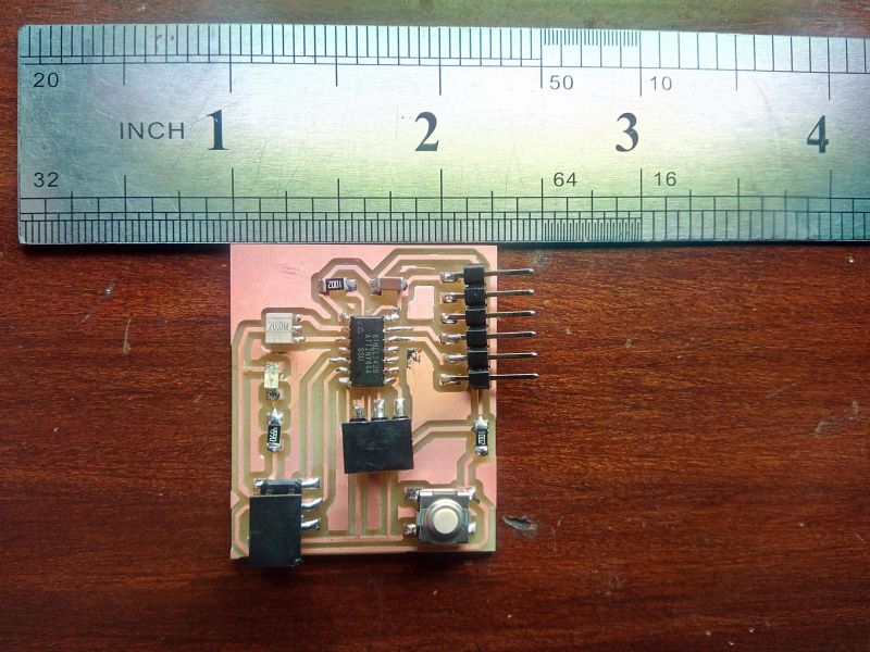
The results are here, satisfying and motivating you to work further:
Part 02- Soldering of Hello World Board:
Following steps were required for the SMT based soldering on PCB
Following components were required for soldering:
I did some good practice in week 06 on SMT before, so this time I did not face any difficulty while soldering the components.
Part 03-Testing the Hello World circuit:
The circuit is ready, now I just need to check its connection and program it using the FABISP programmer.
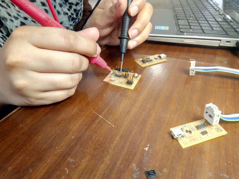
In the next step, I checked if my Hello Board was working fine by using the Programmer FabISP.
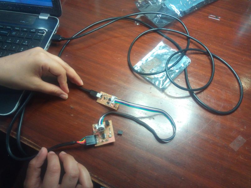
Then I checked it using a simple blink program, if the led attached at pin 6 of Attiny works when operated.
All the Files of Week- 07 are attached below!
Week 07 Files!

This work is licensed under a Creative Commons Attribution-NonCommercial 4.0 International License.