 |
 |
 |
 |
Week3. Computer Aided Design
Assignment
model (raster, vector, 2D, 3D, render, animate, simulate, ...) a possible final project, and post it.
Study Software
-Raster Graphic Editor : GIMP [version 2.8-open source] - download site
-Vector Graphic Editor : InkScape [version 0.92-open source] - download site
-2D/3D CAD(parametric) : Fusion360[conditional] - download site
-2D/3D CAD(parametric) : FreeCAD [Current Stable Version-open source] - download site
* The version of each can be change when download later.
1. Raster Graphic Software
In this section, I learnt about a simple Animated GIF(8bit color Graphics Interchange Format) file. I use two software,one is 'Paint' program in Windows10 OS for making each slide as png format the other is GIMP for making animated GIF with integrated slides.
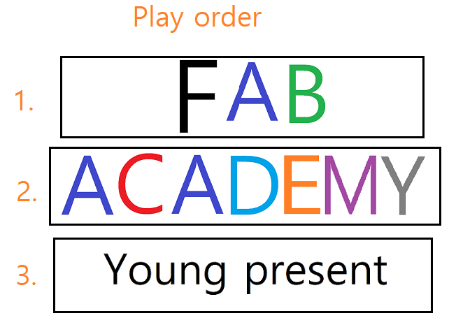
-Scenario : I will show first start capital of 'FAB ACADEMY' next to add each capital till come 'Y' then 'Young present' ending and repeatedly show again.
-WorkSteps.
Using Paint
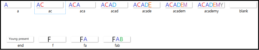
-1. Making the scene images : To this step, set a frame image size to 550x115 pixels(it needs sutable size cause big size ofpixels can make a too big size of file ) then work at blank image through the stacked capitals to ending slide.
Using GIMP
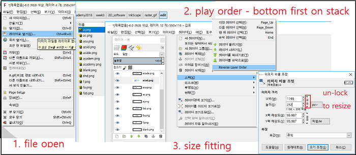
-2. Edit the animated images :After finish the scene makes, change the software to GIMP load the whole images with open as one Layer and play order align on stack(bottom to top order)
if frame size is not to fit image, choice the size to fit image or something to be good shape in image(menu) / stack/ image size(if not want to ratio style, click the rock to free )
I just doing to this sizing work several times(because of final size depands on this setting-I couldn't well estimate about the size.).
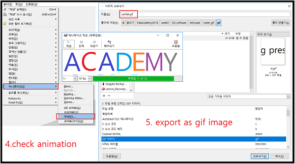
Now, ready to play the scenario, but must be check about speed of show time of each slides and delay time to apply somewhere or everywhere position.
I just put the 500ms before each slide and play speed at 1x. After that export the output file as GIF format.
Here is the animated file. : scene
2. Vector Graphic Software
This section, I want to make a logo from some image silhouette. I just get the image file screenshot. Touch more effect onimage to make easy to draw outline follow the silhouette of image. Then edit the simplified graphic lines to fit adjustable size. It will attach to some surface on next 3D cad section.
Using InkScape
I know inkscape as vector graphic editor similier to adobe illustrator.
But, I didn't know possiblities to make with digital fabric machine.
Here, I study two examples, one is raster image to make vector graphic file,
the other is drawing a base file which is use to cut with CNC.
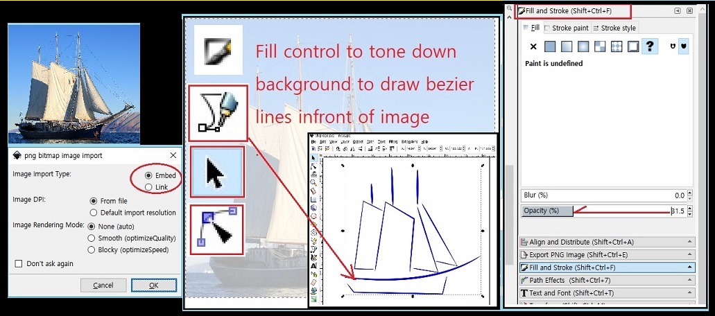
Case1. Edit the Raster image to Vector graphics
WorkStep.
1. Read image file : File / import/ select file. In pop-up windows, check the 'Embed'.
2. Reduce the opacity : For drawing the path on the image, needs to make more transparency of image.
Its be done opacity slide down about 50% in the 'Fill and Stroke' menu button clicked.
3. Draw the path : 'Bezier' button menu help to draw the path lines near the edge points in the image.
It just makes with click to start point and end point of image. after that the line can be modified by
'Edit Paths by ndes' button.
4. Delete the image: After draw the lines, select the base image and delete it.
5. Coloring: If it needs to change color of lines, select the lines desired and chage the color the 'Fill and stroke' menu.
6. One pathline : After all above process, select the 'Path/Combine' menu to make one path.
7. File save : Save the format as .svg , .dxf and png etc.
Case2. Draw machine drawing used for CNC or Lasercutter
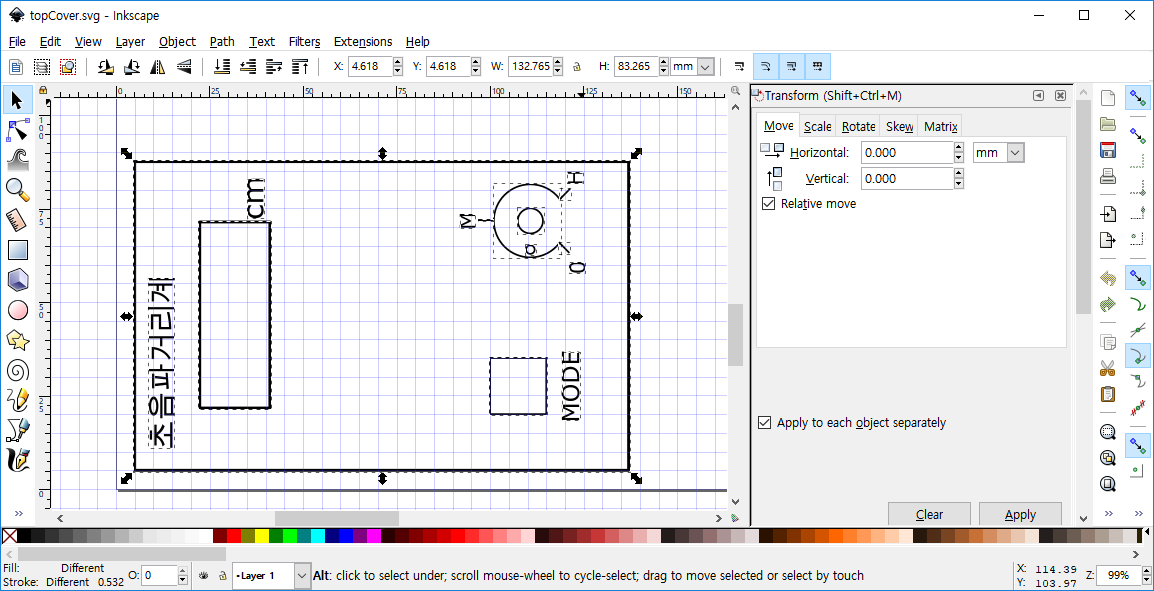
1. Drawing : In this design, start the draw with left drawing tools. also for the precision make sure the size correctly.
2. One pathline : After finish the drawing, select the 'Path/Combine' menu to make one path.
3. File save : Save the format as .svg , .dxf and png etc.
download files:
- raster to vector : svg file|dxf file
- machine case cover : svg file|dxf file
3. 3D Software
Fusion360
In this Program, I try to learn 3D modeling, randering, simulation.
3D modeling
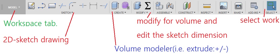
WorkSteps in Modeling workspace
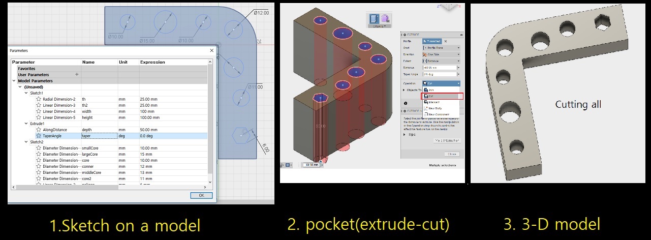
1. Sketch : In 'SKETCH' menu, use square drawing tool make a sketch and add a fillet.
I just put the names to each dimensions for future modification.c(If it needs relational connection,
I will use the parametric equation for this)
2. Base modeling : In 'CREATE'tab, select 'extrude' menu to add a volume.
3. Add a sketch on 3D-surface : For 2nd EXTRUDE work, make a sketch on a surface.
4. Check around: Press a shift-key and mouse scroll button, rotate the model and check the state.
Randering
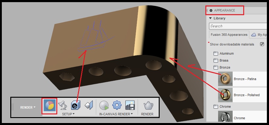
WorkSteps in Rander workspace
1. Rander : In 'APPEARANCE' menu, use some material's color and finishing state apply to the model shape
(this work can be establish individually on each surfaces.)
2. Decal method : I have a image made from the InkScape work. Import this image and stick on a surface of model.
Simulation
Trial Run
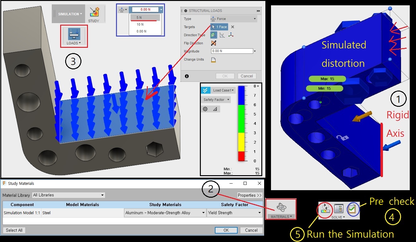
WorkSteps in Simulation workspace(1st run)
1. Constraint set : Set one edge line.
2. Material set : Select a Aluminum Moderate-Strangth Alloy.
3. LOADS set : Select a plane inside of rigid axis and 5N power on.
4. SOLVE(pre-check) : If there some errors on coonfiguration, it will guide where to go make-up.
5. SOLVE(solve) : If there are no errors on pre-check, this command will make some simulations.
** My first run is a little bit different in mind so, I try to 2nd run with another conditions as below.
Analysis 2nd run

1. Constraint set : In this time I just change set to the plane to rigid.
2. Material set : Select a Aluminum Moderate-Strangth Alloy(same as 1st-run).
3. LOADS set : Select a plane outside of rigid plane and 15N power on.
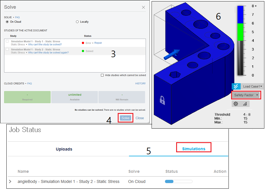
4. SOLVE(pre-check) : No errors on coonfiguration.
5. SOLVE(solve) : It makes show as above, I can find well move the stressed part
follow to 'Defomation Scale' in 'Load Case1' windows.
Finally, I can find the amount of the valus and stressed positions as mentioned about
'Displacement', 'Reaction Force', 'Stress' and 'Strain' in order left to right direction as below.
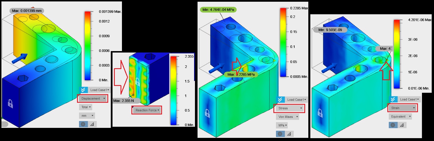
* The arrows indicated to the maximum point of each analysis.
download file:
- model (Fusion360 format) : angleBody.f3d
FreeCAD
In this Program, I try to learn parametric design for a simple cylinder example.
And, show about how to apply the numeric parameters on 3D model.
Parameter's Table
At first make spreadsheet contain for a set of numeric data. The tool name is 'Spreadsheet' Workbench.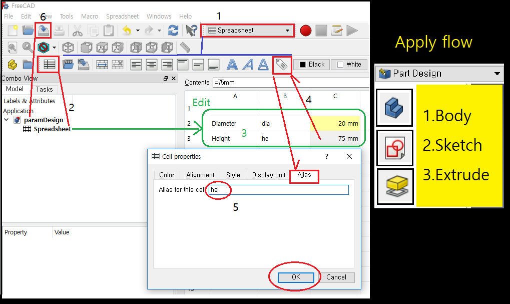
Work flow.
1. Start the Spreadsheet workbench with in File menu to create new project.
2. Create the new spreadsheet to show the table. Than, save as paramDesign.
3. Make new parameters as 'diameter' and 'height' of cylinder.
I just put the initial values one is a 20mm for the diameter the other is 75mm for height.
Parts Design as 1st data apply.
4. Now, change the workbench to the 'PartDesign' module and create a new body with click the 'new body'icon.
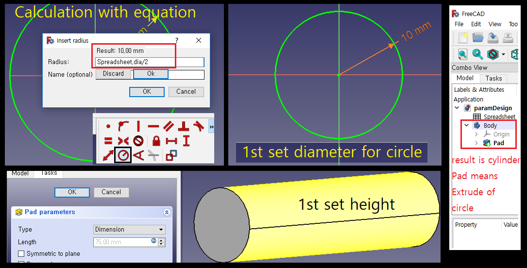
5. Than create a sketch on x-y plane for make a circle. Edit to this circle diameter as equation of parameter
on the 'dia' value on spreadsheet.
Parts Design as 2st data apply.
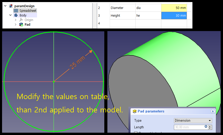
6. Again change the spreadsheet data as different value for modification of 3D model.
7. Than its apply to the model automatically shown as above.
download file:
- model (FreeCAD format) : paramDesign.FCStd
Sketch for Final Project
In this week I made design for case outline model. Here is a assembly shapes, but not detailed.At first, draw about volume of assembled exterior.There are three cases consist of one amp system,
I will modify after build up inside of housing.
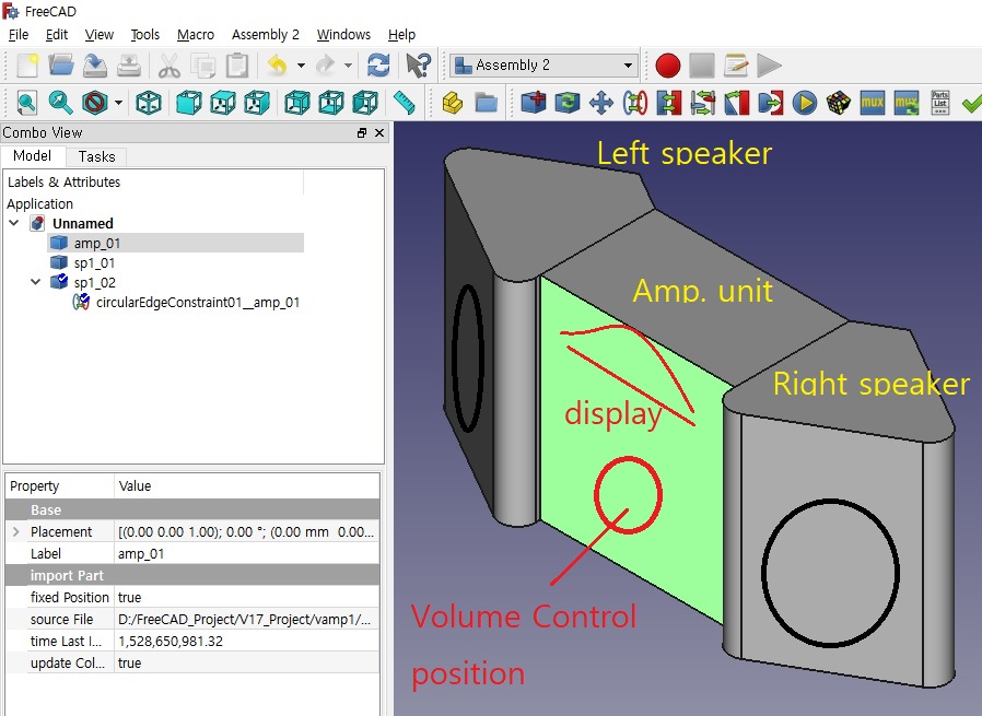
In this design, I join together with 2 speaker boxes and ampifier box in the middle. But, after some joint
below the bottoms of box. Those some graphics in front of the case cover just virtually installed speakers
and volume and LCD screen etc.
download file:
- model (FreeCAD format) : asmhouse.FCStd
*This file is a assembled model which is consist of 3 pieces case.
| Week2 | Week4 |